
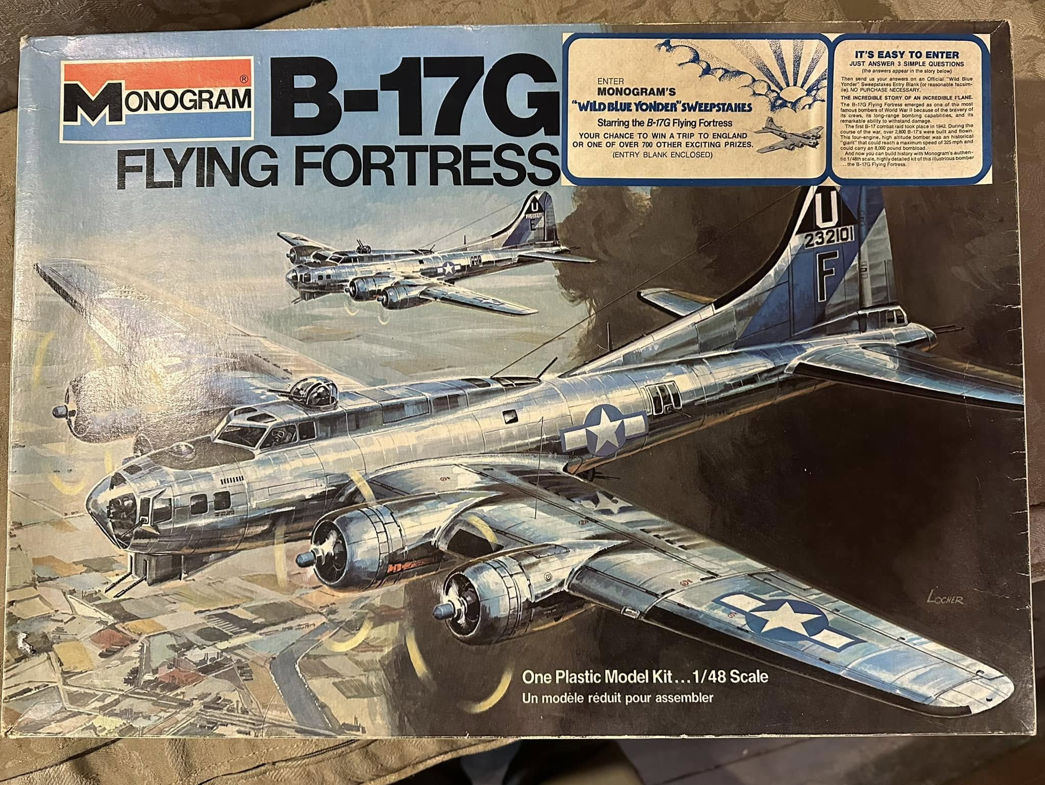
It almost goes without saying:
If you love airplanes, you have probably built a few plastic models.
And if you love the Boeing B-17, then one of those models was probably Monogram’s 1/48 scale B-17G.
I have certainly built my fair share over the years!

These pics came from my very last one, and you can probably see that I was not a particularly good modeler. I gave up modeling once I joined in working on Lucky Thirteen. Honestly, I find working on the real thing easier than building models, which the rest of team finds hilarious. Still, I have a deep love of the hobby and follow the work of others with fascination.
First released in 1975, Monogram’s 1/48 Boeing B-17G is easily one of the most successful plastic model kits of all time. Even in recent decades, with popular companies like Tamiya and Hasegawa producing kits with meticulous proportions and detailed interiors, the Monogram B-17G remains competitive.
Much of this is due to the fact that few other companies would produce 1/48 kits of large aircraft. It was a risky business venture, and one for which Monogram should be commended. For a long time, the only alternative to the Monogram B-17G was Revell’s B-17F, released in 1977. Featuring no interior detail whatsoever, rumors arose that the kit had been based on Monogram’s release, and the evidence was pretty damning. Still, the question became moot when the companies merged in 1986. So, the Monogram kit marched on without a competitor for an incredible 44 years.
The release of an updated kit, with more interior detail and engraved panel lines, was long awaited in the modeling community. And, for the most part, the new HK Models 1/32 and 1/48 kits have been well received. But B-17 aficionados the world over have noted that, even with all the benefits of modern technology behind them, the HK kits just do not look right. This criticism is justified – the HK kits do indeed suffer from some serious proportional issues.
But the thing that really astonishes me is the fact that, despite using slide rulers instead of the modern computer design programs, Monogram was still able to create a more accurate visual representation of the B-17 all those years ago. A true testament to those responsible for bringing it forth.
Scale modelers have always been some of our biggest supporters, and for a long time, we have toyed with the idea of going over the Monogram kit in detail. The idea being to compare and contrast the kit with the real McCoy.
Now we are doing just that.
The kit pictures shown here come from Trystan Bennet of Fredericksburg, Virginia, who was able to locate a rare, early-print of the Monogram release. The quality of the molds are far crisper than the releases currently available today, and give a better idea of exactly what Monogram was trying to achieve.
The details within suggest that Monogram was trying to balance characteristics of the B-17F and G variants into a single kit. Their efforts were admirable, though they ultimately limited modelers to early-Gs, as anything else required severe alteration. But then again, you have to get into the finer details to see some of what we are talking about.
So let’s get on with it –
*Please note that this article is by no means definitive. To keep from overwhelming our readers, the focus has been limited to those areas covered by the model kit.
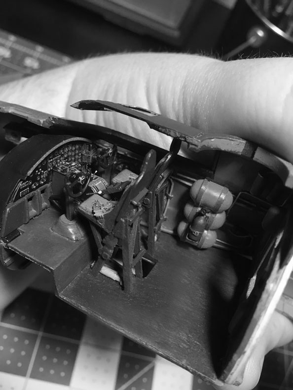
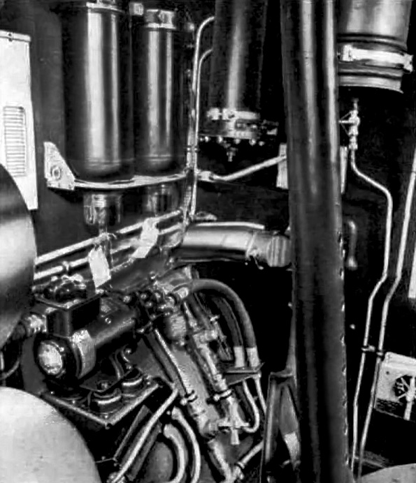
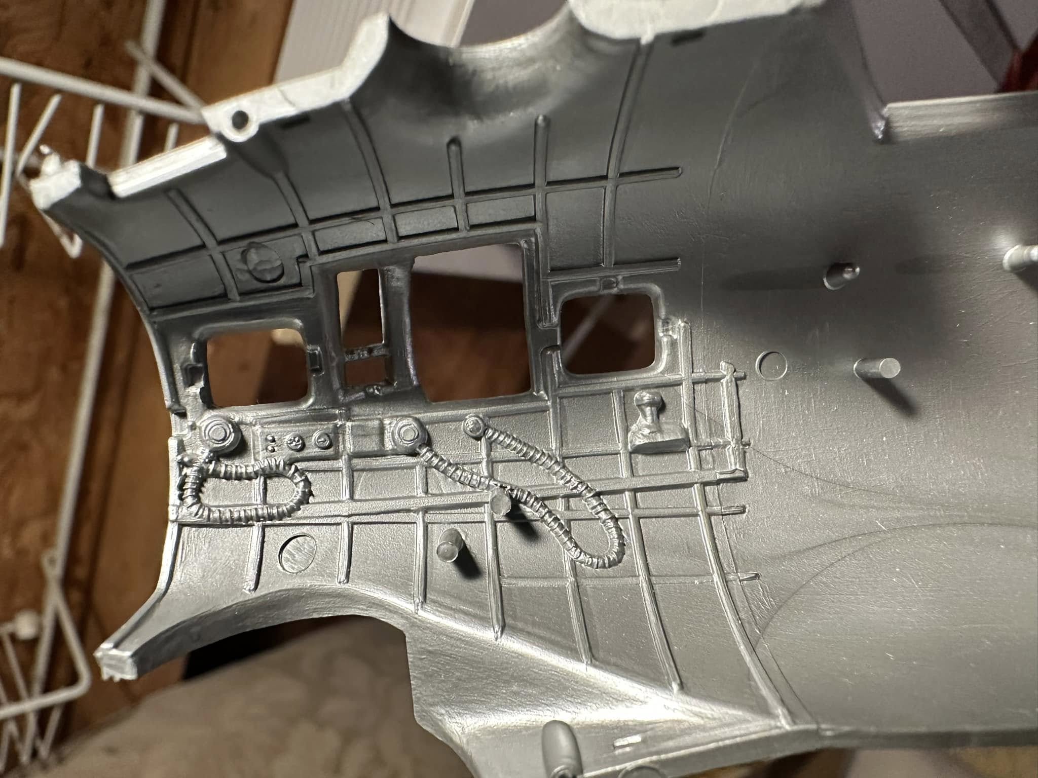
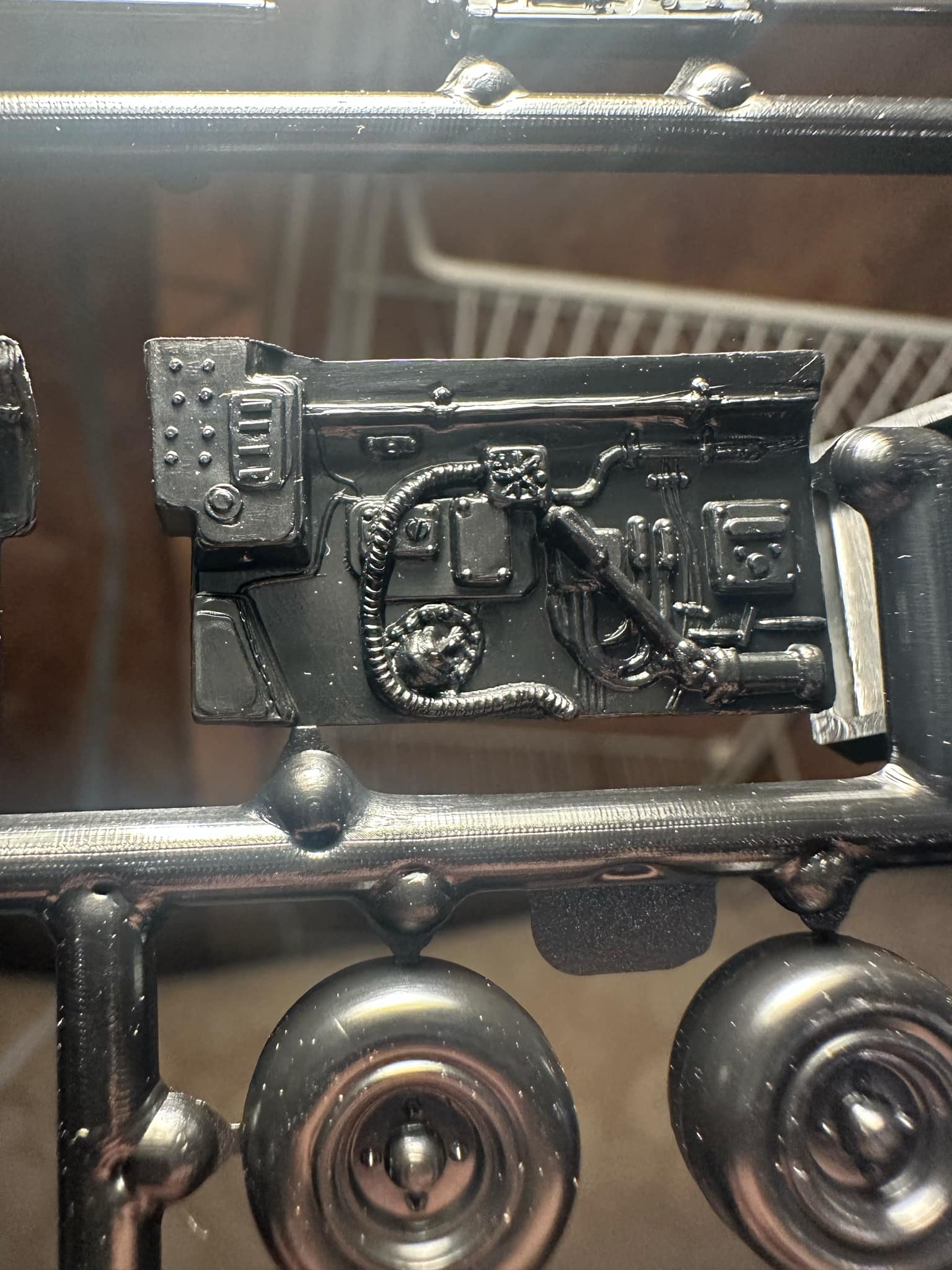
Starting with the right side of the cockpit, the largest inaccuracy is the presence of ribbing on the walls. All B-17s, regardless of variant, had insulated cockpits covered with fabric sheets. The fabric was bronze green cotton and had a smooth texture, the tube-stitched insulation being hidden underneath.
The three cylinders at the top are the first example of an F characteristic finding its way into this G. The two cylinders on the right represent the aircraft’s thermos rack, which was common to both variants. However, the cylinder on the left is the hydraulic accumulator for the emergency brake. The emergency brake was unique to the F, being controlled by a pair of pull handles mounted above the pilots’ heads. The accumulator was changed partway through the F-series, being made longer. Since this seems to represent the smaller variant, it suggests that Monogram referenced an early-F for this area.
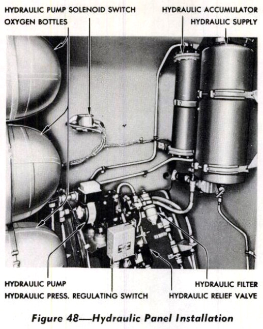
The objects below the three cylinders are a crude representation of the B-17’s hydraulic control panel. This area changed little throughout production, holding the electric pump and filter for the hydraulic system. Unlike most heavy bombers of the period, the B-17 carried few hydraulic systems, the only ones being the brakes and cowl flaps.
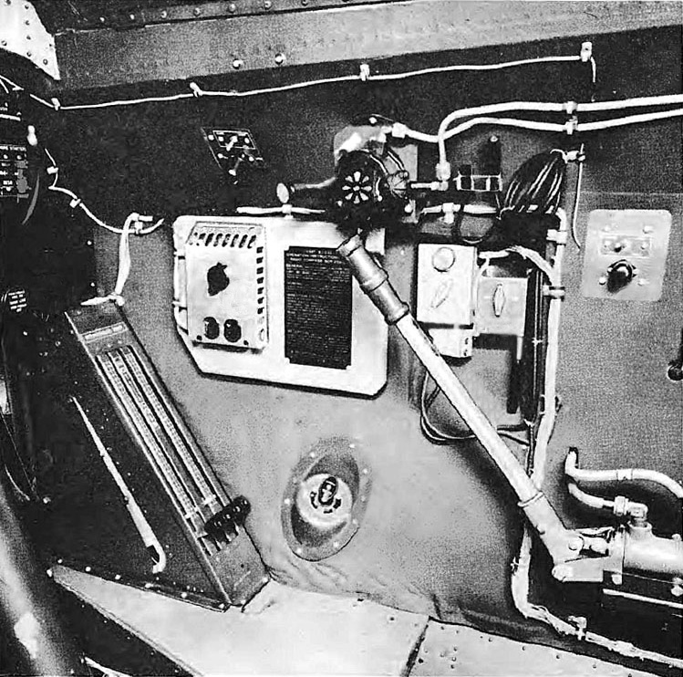
Manual illustration of this same section aboard a B-17G.
Because this aircraft lacks an emergency brake, the cup dispenser for the two thermos bottles has been moved from behind the copilot’s seat to the emergency accumulator’s former position.
Note that the hydraulic system’s primary accumulator (left) and reservoir (right) are on the back wall (Station 4). The cockpit door on the right, cut off in the photo, sits above the fuel transfer controls.
The large pipe partially blocking the view is one of two legs on the aircraft’s upper turret. Two of the three oxygen tanks on the cockpit’s right side are visible on the left.
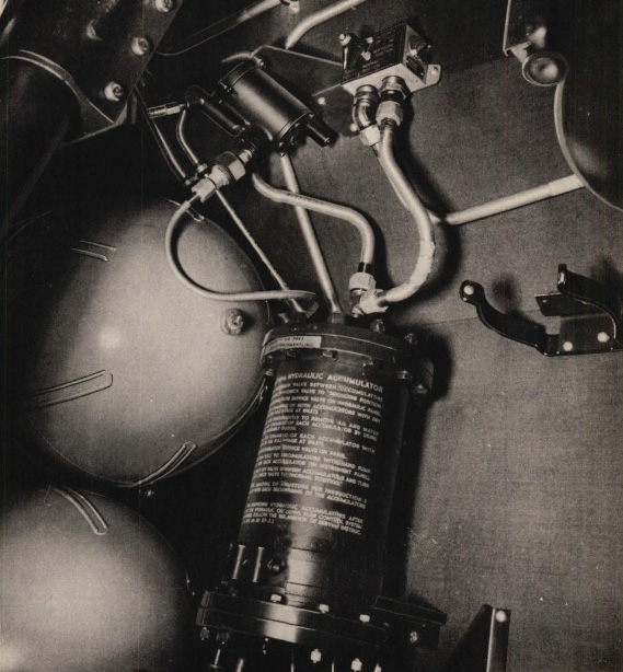
The hydraulic accumulator for the emergency brake aboard an early B-17F.
The fact that this is an early-F can be ascertained by the oxygen regulator at the top. This is a regulator for a constant flow oxygen system. These oxygen systems, typically associated with A-8B oxygen masks and their distinctive rebreather bags, used thin rubber tubing rather than the large ribbed hoses molded in the Monogram kit.
Note the clamp on the right, used to hold a thermos bottle in place.
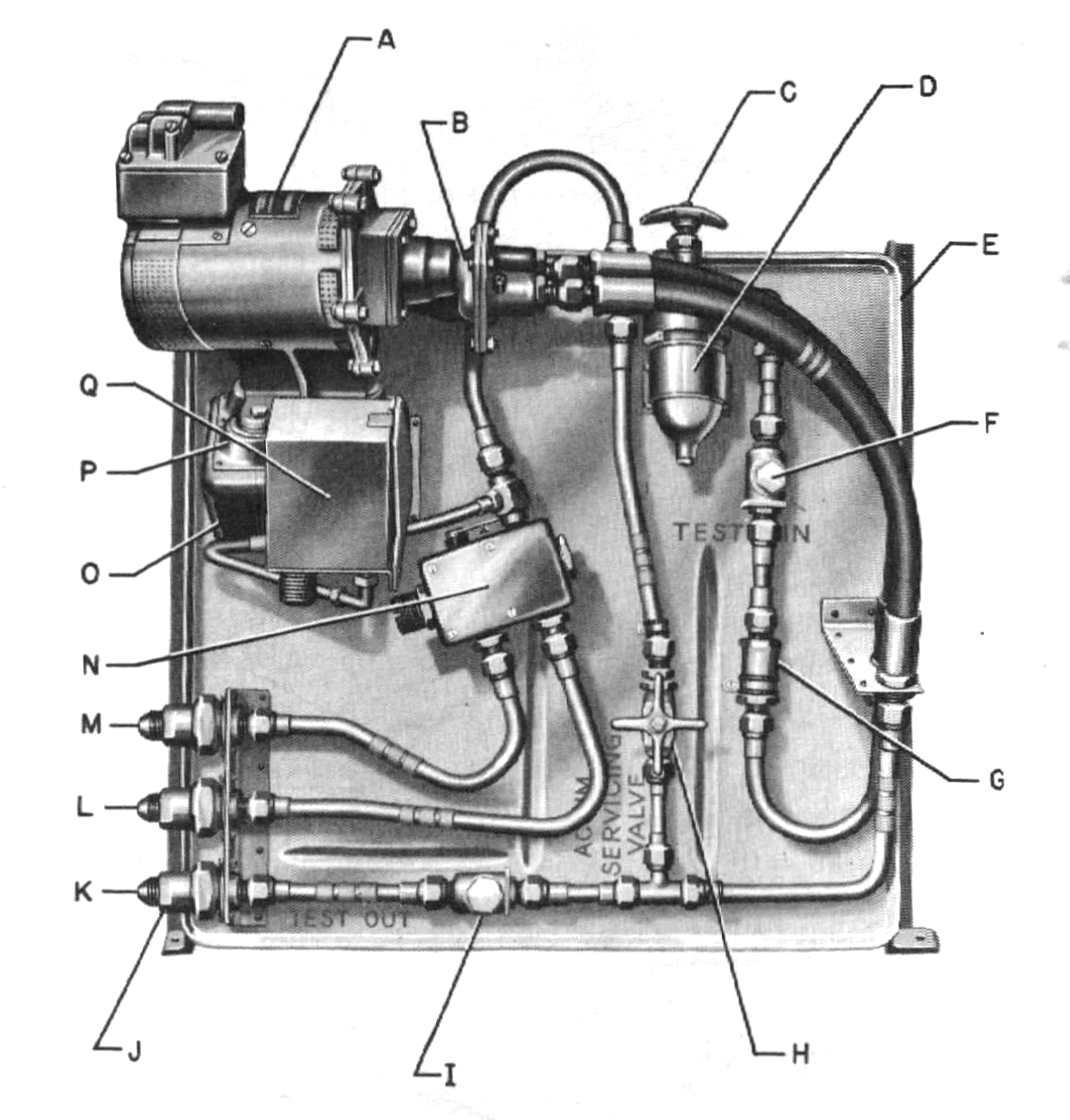
Manual illustration of the B-17’s hydraulic control panel.
The reservoir tank feeds into the system via coupling (K), splitting between the pump (A), check valve (G), and main valve (H). The main feeds into a relief valve (N) which splits the feed between the reservoir return (M) and accumulator (L). The pressure switch (Q) is designed to permit ranges of pressure between 600 to 800 pounds per square inch.

Aircraft thermos bottles acquired for Lucky Thirteen in 2018.
Due to too many projects and not enough volunteers, the rack for mounting these units has not yet been fabricated. If anyone is interested in trying to tackle this project, just let us know!
Moving on to Station 4, the back wall of the cockpit, the detail here is surprisingly accurate. The issues herein are primarily ones of scale.
For example, the hydraulic accumulator appears far larger than the reservoir. While the accumulator was thinner, the reservoir was certainly the larger tank. The piping for these pieces is generalized.
The CO2 extinguisher on the right is oversized, though more-or-less in the correct location.
The fuse panel is far too small. On Fs, the large fuse panel was joined by a smaller one on its right side, while Gs only had the one large unit.
The cockpit door is correctly shaped, though the objects on the door are a mixed bag. The handle is shown attached to a round plate when the real plate was square, the two upper charts are misaligned, and the lower folder is large and misshapen.
The armor plate above the bulkhead and the fuel transfer valves below the door are accurately modeled. The piece between the two transfer valve controls is a leather pad to avoid scuffing – a small detail that I am surprised Monogram noticed.
Manual illustration of a B-17 without an emergency brake system or cockpit thermos bottles.
The size and shape of the hydraulic accumulator and reservoir are visible here.

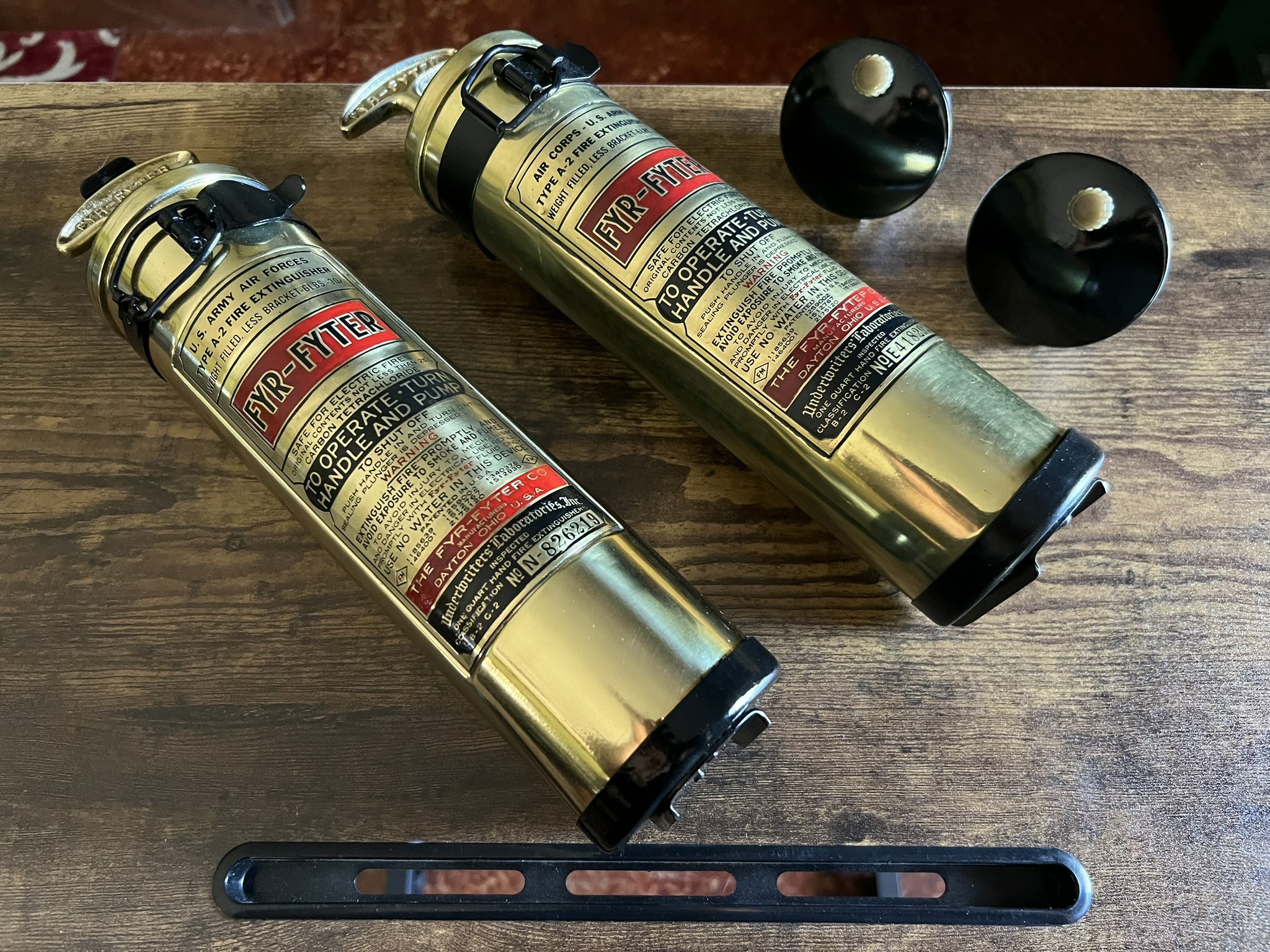
One of the CO2 extinguishers restored for Lucky Thirteen.
Most B-17s carried three CO2 extinguishers, being located in the cockpit, nose, and radio compartments. Two CO2 extinguisher variants were used: the A-17 and 4TB. Both used the same cylinder, the major difference being that the 4TB had a handle and trigger assembly.
It is a common misconception that aircraft extinguishers were red. They were not. Aircraft extinguishers were gray. The unit above was color matched to an original example.
Photo taken 20 June 2023.
![]()
Manual illustration of the fuel transfer controls below the cockpit door. The green leather scuff pad is visible here as well.
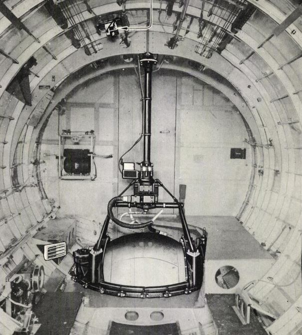
The round object at the bottom is the base of the upper turret.
Several internal details, like the body for the upper turret, were not included in the original release, only becoming standard after the release of a kit which included a transparent left fuselage piece.
The B-17’s upper turret was the Type A-1, designed by Sperry Gyroscope but manufactured by Steel Products of Springfield, Ohio (SPECO) and Emerson Electric of St. Louis. Monogram’s representation is rather simple, omitting the distinctive V-braces which hang below the turret’s tub and hold its ammunition cans. Here, they have elected to strengthen the V-shaped brackets which attach the frame to the tub by including a large square shape behind them to vaguely represent the ammo cans. In reality, each gun was fed by three cans, hanging on either side of the V-braces on the bottom of the tub assembly. Admittedly, this would be difficult to portray at this scale
The turret as shown is accurate for a late-A-1 or an Emerson-built A-1A. (Generally speaking, A-1s were used on B-17Fs and A-1As on Gs.) The defining characteristic is the small bump in the center of the base plate. This is the cover for the turret’s oxygen swivel assembly. Early A-1s lacked this piece, requiring their own oxygen tank, which was mounted on a swivel at the front of the tub assembly.
During the G-series, SPECO introduced measures to cut down on the weight of the A-1A, reshaping the base, tube attachment brackets, and tub assembly. These changes ultimately led to a major redesign with the A-1B.
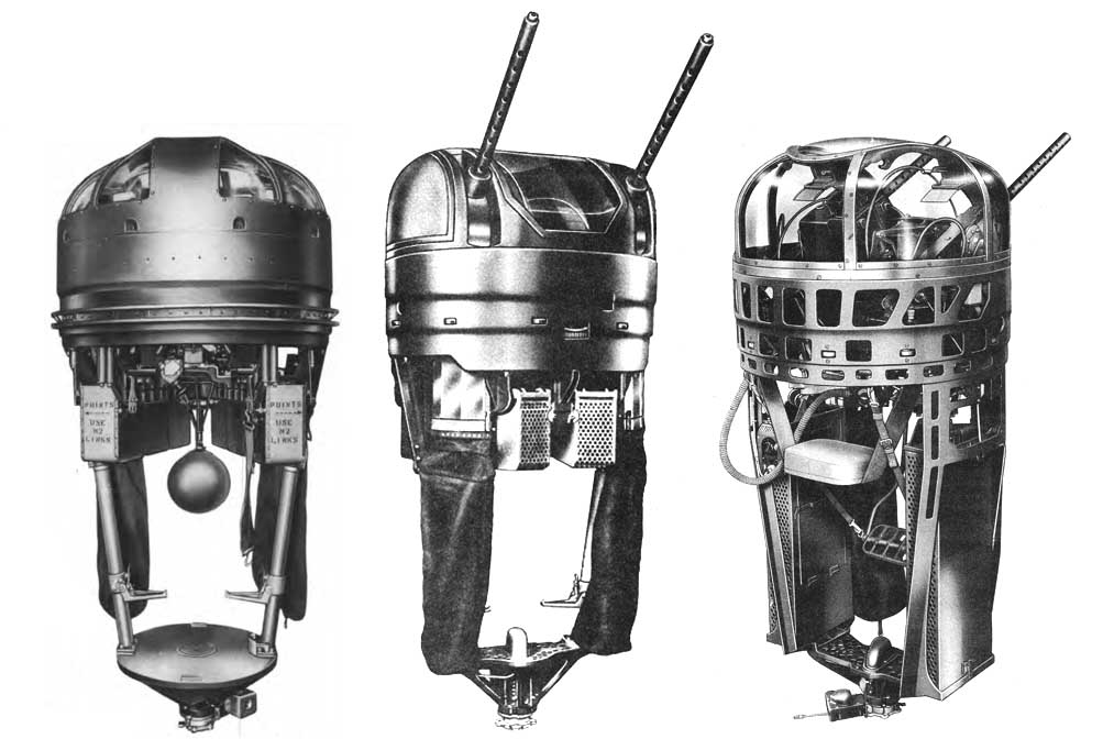
From left to right:
An early A-1, a SPECO built A-1A, and an A-1B.
Once again a testament to their research, the turret provided in the Monogram kit is accurate for the early-G which it is meant to represent.
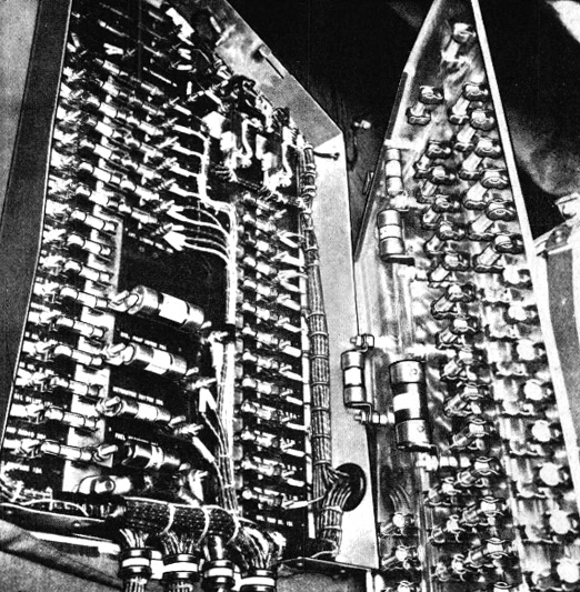
Manual photo of the B-17’s cockpit fuse box. While the opened faceplate is obscuring the second box on the right, we can still see evidence in the wiring that this is an F. The inside of the cover plate is adorned with spare fuses.
Restored aircraft often redo this area entirely, replacing the fuses with modern circuit breakers. One of a plethora of reasons to avoid using modern restorations as reference. 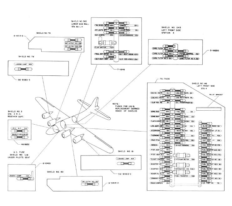
Manual illustration of the various fuse boxes found aboard a standard B-17. A typical panel layout found in the cockpit fuse box is shown on the right.
The second largest fuse box (upper center) was mounted on the wall by the ball turret.
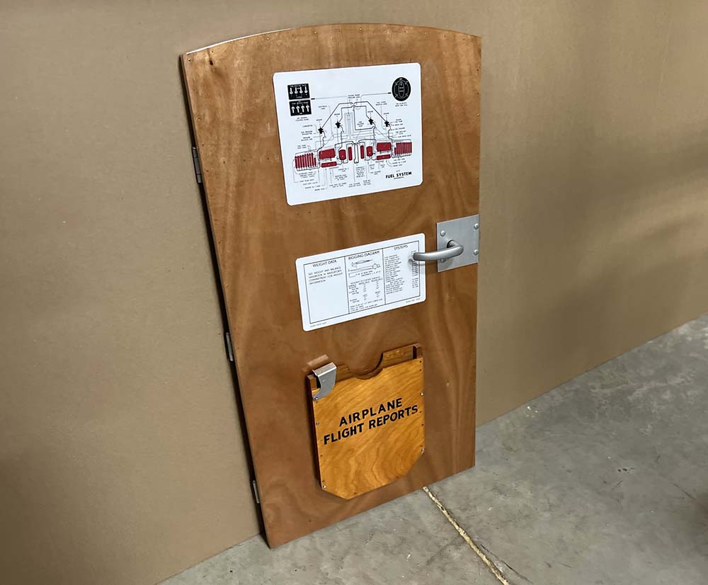
The cockpit door of Lucky Thirteen.
The upper chart is a fuel system diagram and the lower chart a listing of the system blueprints applicable to the aircraft. These prints were kept in a box mounted to the back of the copilot’s seat. The Flight Reports Folder at the bottom is wartime original, as is the door’s hardware.
Photo taken 11 January 2023.
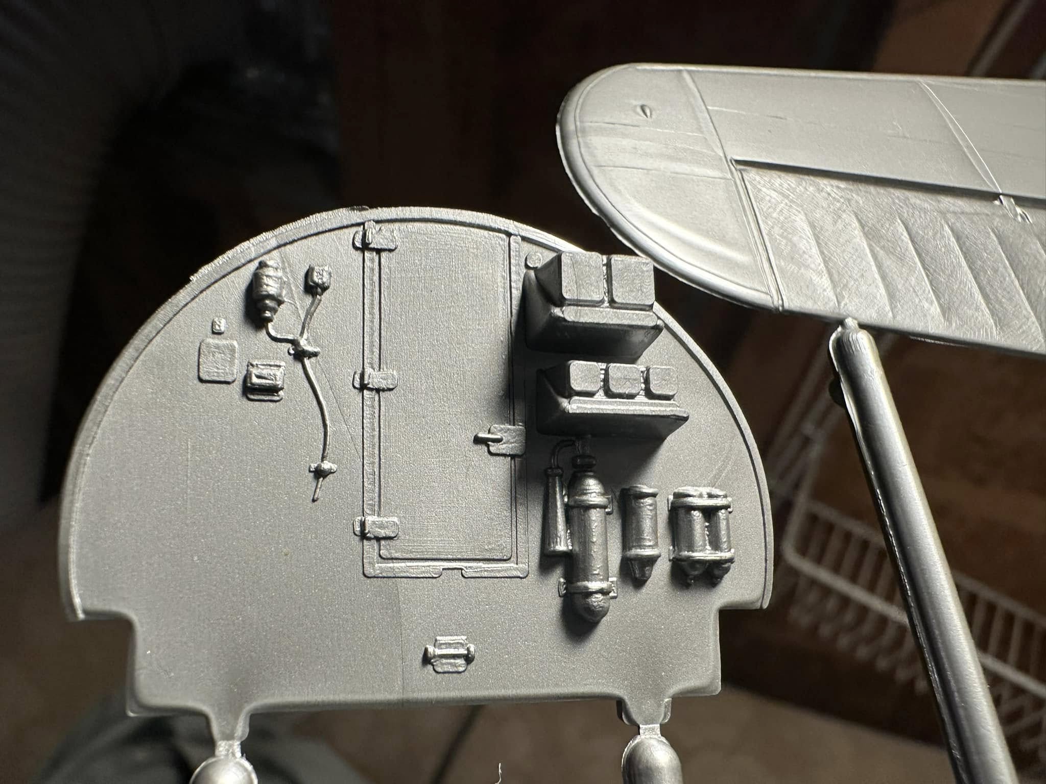
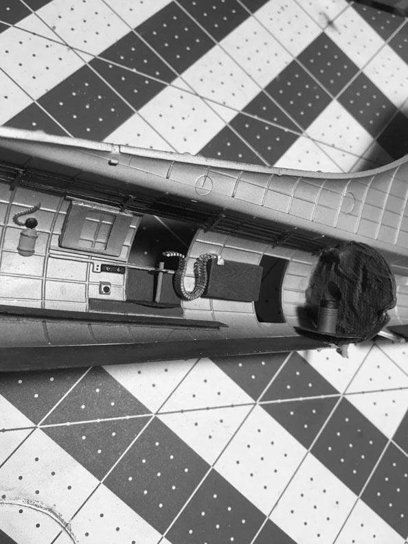
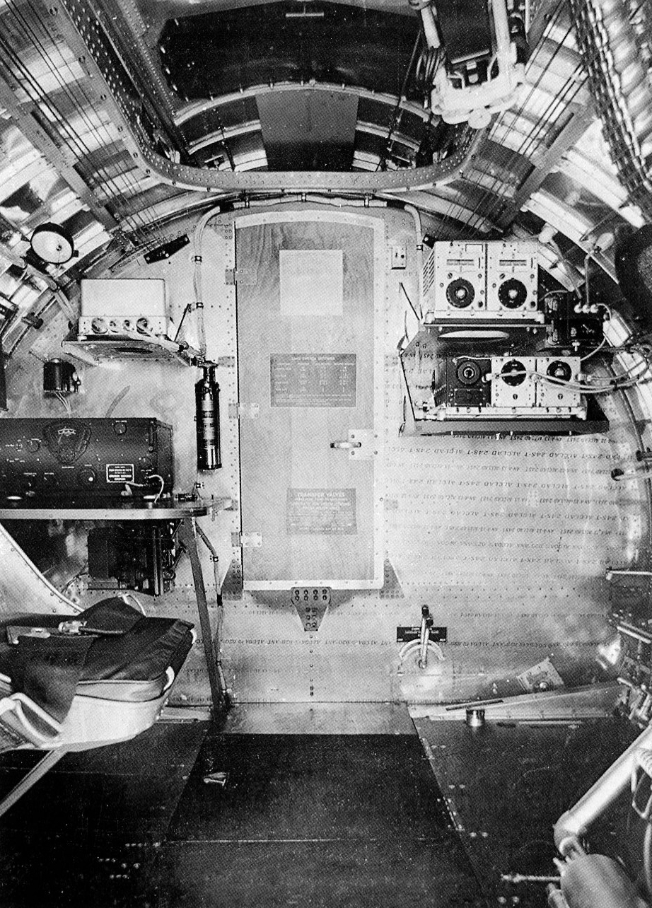
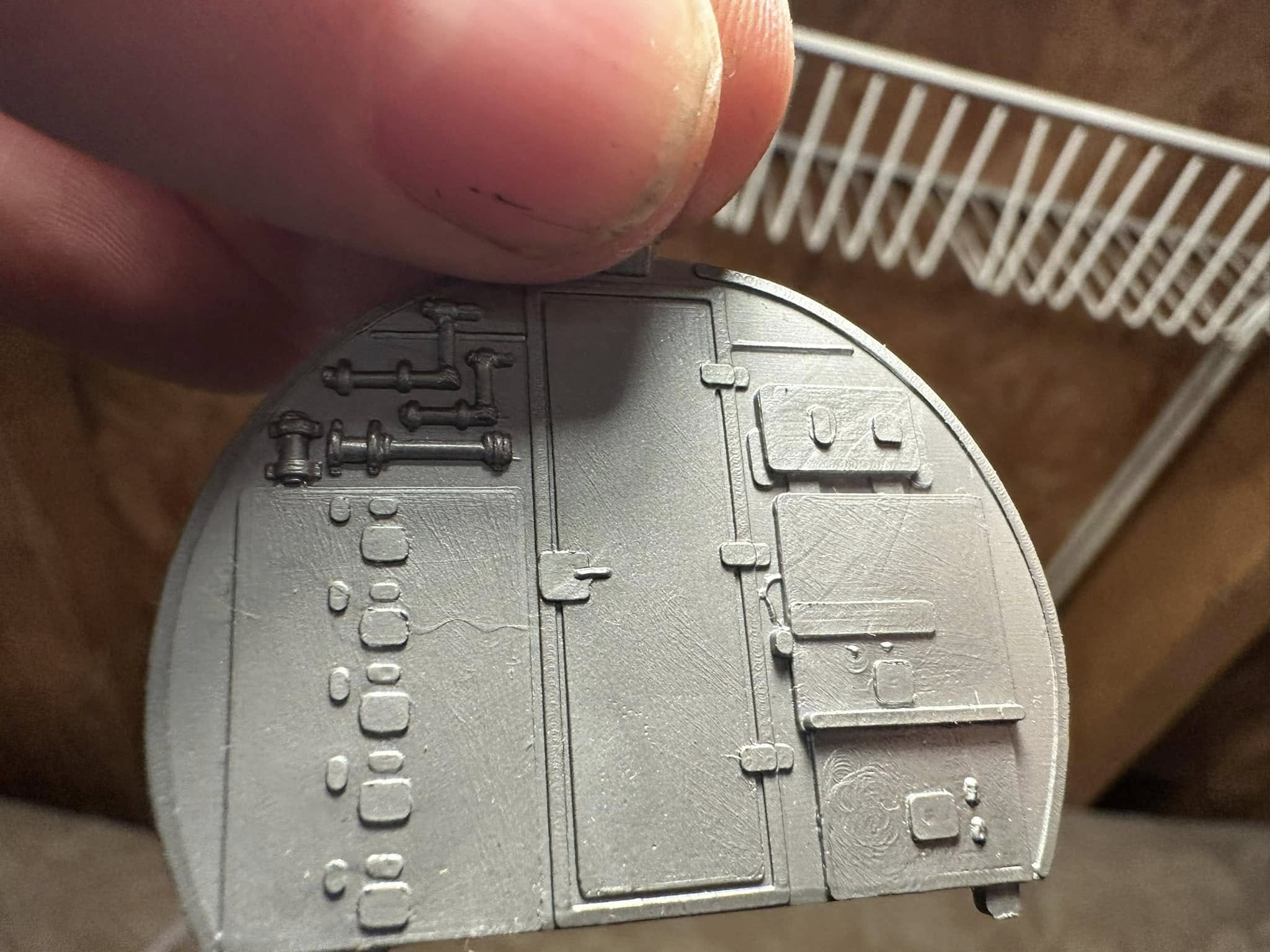
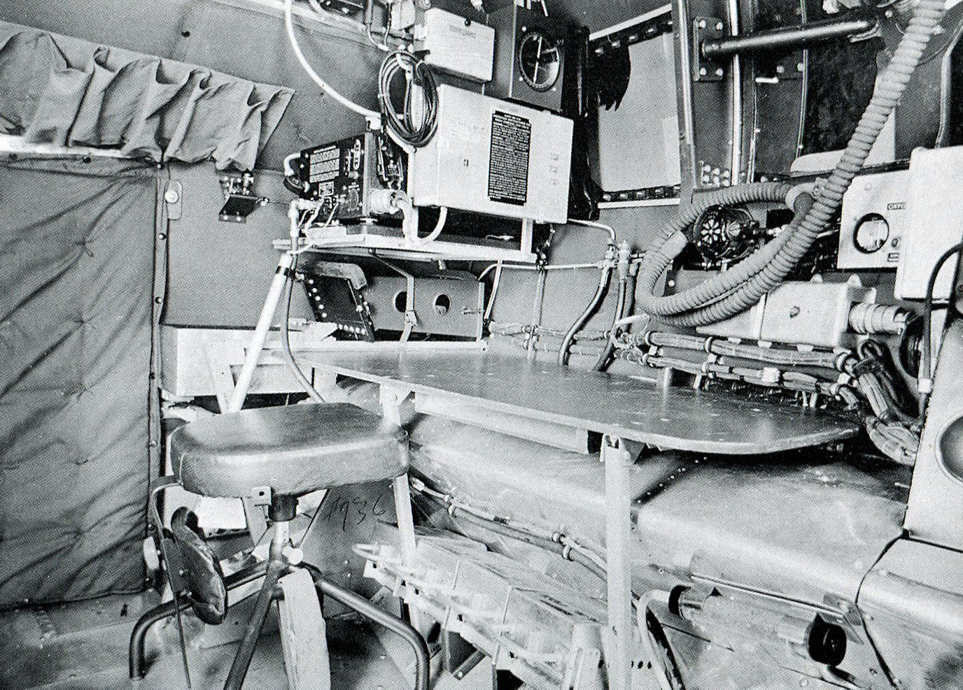
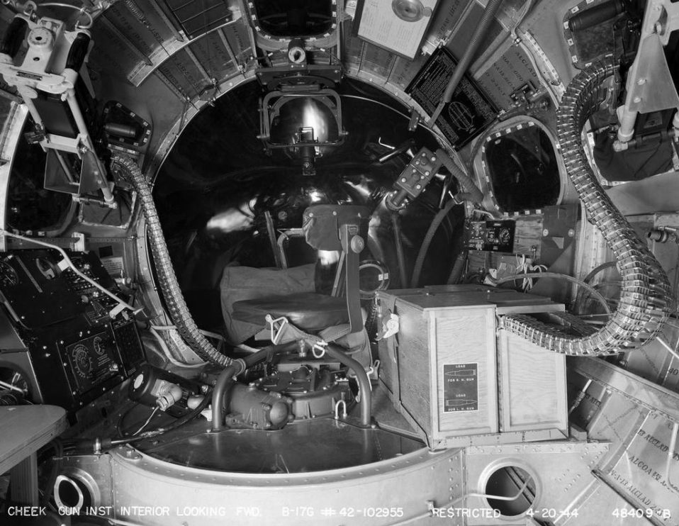
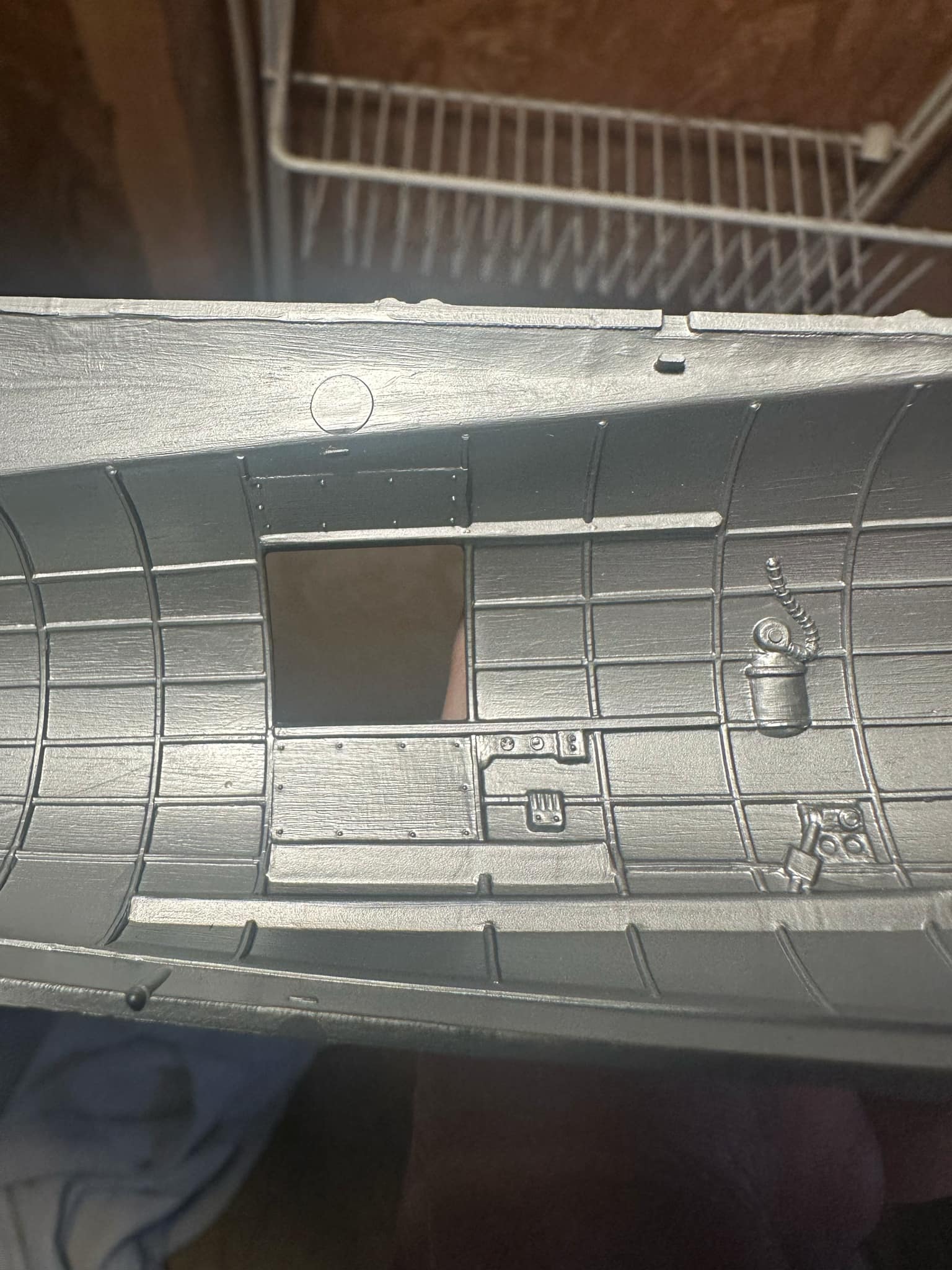
Station 5, the front wall of the radio compartment, as portrayed in the Monogram kit.
The layout here is a mashup of F and G types, with a definite lean toward the former. There are two clues for this. First is the border around the door. While the Station 5 door had a lip, Gs did not have a border around the opening itself, as said trim was only used on insulated radio compartments. Prior to the G, the radio compartment was insulated. Like the cockpit, this was done with smooth panels of bronze green fabric. The other clue is the location of the command radio’s modulator. On Fs and early-Gs, this unit was mounted on the floor – which is how Monogram molded it – but for the majority of Gs, it was kept on a shelf above the liaison radio receiver, necessitating the move of the IFF controls.
Incidentally, the large Y-shaped piece on the left is intended to be the IFF controls. The wire leads up to the IFF inertia switch (left) and control box (right). It was against regulation to photograph IFF equipment and it appears Monogram based the design of their Station 5 on photos which followed this regulation, as the control box is missing and a small square blob molded in its place.
The two square shapes to the left of the IFF controls are meant to be the intercom call light (above) and bailout bell (below).
Just to the right of these pieces is an odd shaped piece which resembles a first aid kit. This location was only used for a time in the G-series as, typically, the radio compartment’s first aid kit was stowed above the liaison antenna tuner.
Below the door is the clip for the radio operator’s safety belt. This was a strap to keep the radio operator onboard should he be standing when the aircraft lost control. Prior to the B-17G, when the radio compartment was insulated, the space under the door featured another green leather scuff pad.
While shown with inaccurate style straps holding it to the wall, another CO2 extinguisher is visible under the Command Radios. The scale is more accurate this time.
The three objects to the right of the extinguisher are a curious mix. Some B-17s mounted a small, brass carbon tet extinguisher next to the CO2 unit. (In fact, Lucky Thirteen was one of them.) Likewise, there were a few aircraft which stowed a pair of walkaround oxygen bottles to the right of the extinguisher. However, the shapes of these pieces are altogether wrong if that was the intention.
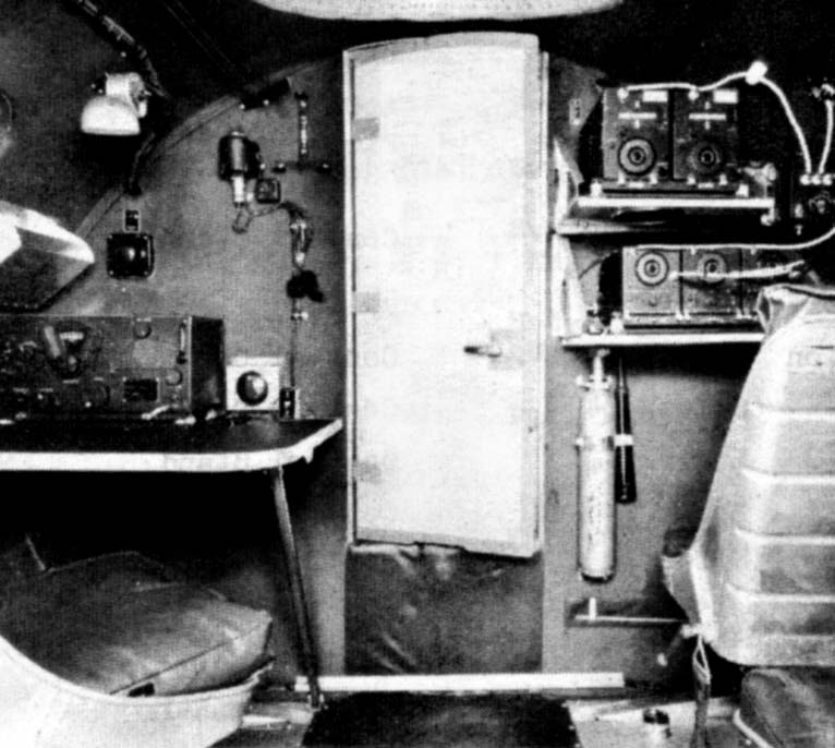
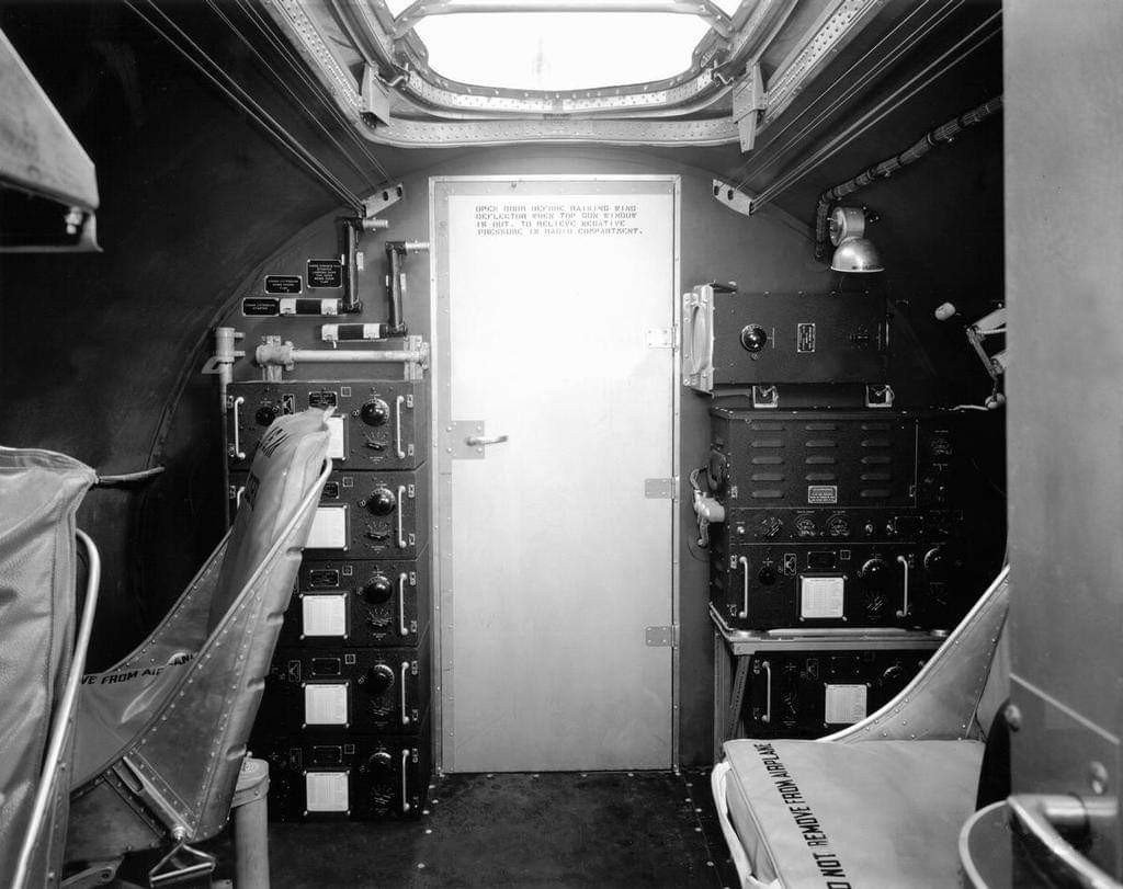
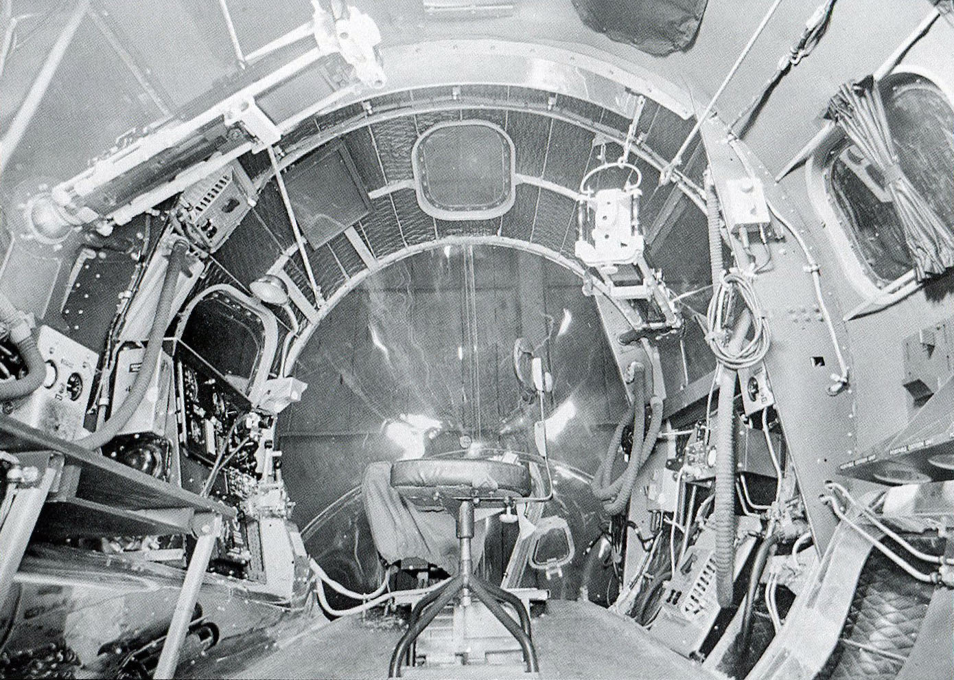
Manual illustration of Station 5 aboard a relatively early-F.
Note the two extra seats on the far right. These were removed from combat aircraft as they interfered with ditching procedure. For this reason, they were quickly omitted from factory production.
The command radios came in both black and silver variants, with black being typical of older units. The vast majority of wartime command radios were silver. The transmitters (top), receivers (bottom), and antenna relay (right) are visible here, while the extra seats are blocking the modulator on the floor.
Speaking of the floor, a nozzle can be seen sticking out just below the forward passenger seat. This is the prop de-icer tank. The small, horizontal bar on the wall above is a dipstick for checking its contents.
Note the radio operator’s seat on the left. Up through the early-Fs, this was a bucket seat, often with an armor plate attached. This was eventually replaced with a Cramer posture chair. Partway through the G-series, the bucket seat was returned, sans armor plate.
The radio operator’s desk seen here is an early variant with a brown linoleum top and bare metal trim. This was quickly replaced in production with a wooden table, which was usually painted bronze green in insulated compartments and left natural wood in bare metal compartments.
Two additional items shown here not on the kit are the navigator’s ashtray and liaison master switch, both to the right of the liaison receiver. The ashtray was removed and the switch inlayed on the table on B-17Gs.
Manual illustration of Station 5 aboard a relatively late-G.
Note how the IFF controls have been moved (to Station 6 near the ball turret) and the command radio modulator placed on a shelf above the liaison receiver. Only the IFF’s inertia switch remains.
The CO2 extinguisher is also missing, a characteristic of late-Gs, leaving only a single carbon tet unit above the radio operator’s desk. The fuel shut-off valves have been moved from the bomb bay into the radio compartment, with two under the desk and two on the right wall. Where the CO2 extinguisher used to hang is now controls for the heating system.
Note the floor. The B-17’s wooden floor was largely covered with pyramid-type rubber matting. In the previous picture, it only covered the center of the floor, while on this G, it covers the entire radio compartment.
Partially obscured on the far right is the aircraft’s auxiliary power unit. On older aircraft, this piece was kept in the back across from the main entry door. Most Gs treated the APU as ‘fly-away equipment,’ meaning that it came with the aircraft, but was meant to be kept by the ground crews.
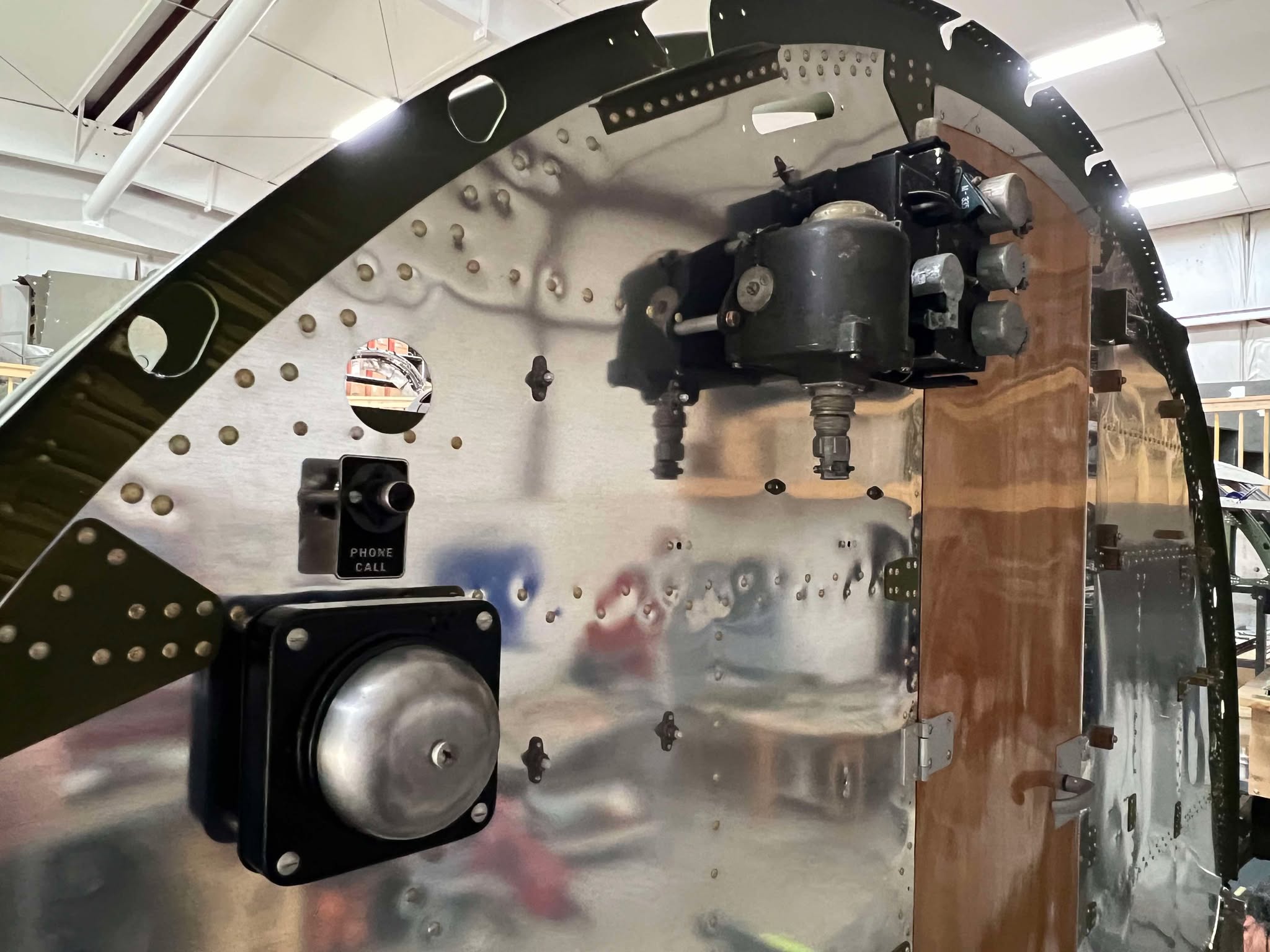
Progress shot showing Station 5 of Lucky Thirteen.
The call light and bailout bell are closest to the camera, while the IFF switch and control box are closer to the door. Spacers hold these pieces off the aluminum in anticipation of future fabric and insulation.
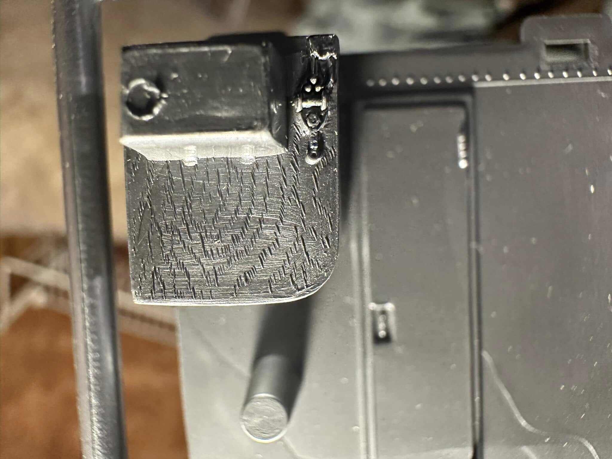
Bailout bells came in both black and silver varieties.
The IFF inertia switch was one of two pieces designed to set off a self-destruct charge in the aircraft’s radar transponder. If the pilots failed to do so manually, the inertia switch was designed to set off the charge should the aircraft be violently shaken (i.e, destroyed). This was to prevent Allied IFF frequencies from falling into enemy hands.
A First Aid Kit is highlighted in this picture taken aboard an early B-17G.
Note that, while the IFF inertia switch and control box are still here, the first aid kit is large enough as to overwhelm the original location of the call light and bailout bell.
The screen in the Station 6 door is characteristic of B-17Gs. This door originally had to be open when using the radio hatch gun, to equalize air flow. However, spent shells from the hatch gun would often slide into the ball turret’s gearing. To help, the Station 6 door was often sawed down, or even removed entirely, on older aircraft. The screen window, introduced on the B-17G, solved this problem.
The radio operator’s desk as molded in the Monogram kit. Despite the mold release mark on the liaison receiver and the odd design molding the table as part of the floor, the resolution is still impressive. The CW Key is even visible on the desk!
The door shown in the floor is meant to represent the pit for the strike camera. While the location is correct, Monogram made the hatch more impressive than it really was. The actual hatch was virtually indistinguishable from the rest of the floor when closed.
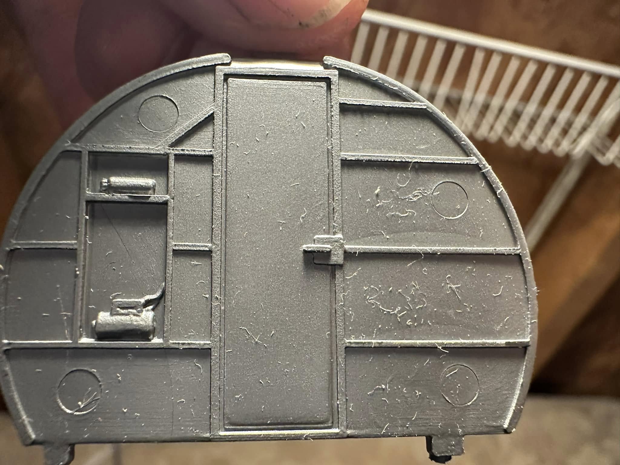
Station 6, the back wall of the radio compartment, on the Monogram kit.
Overall, the details here are not bad in terms of accuracy. They are just rather generalized and, for whatever reason, lacking in depth.
The stack of tuning units on the left for the liaison radio transmitter have been amalgamated into a single large shape. Even still, they are out of scale. Note the hand cranks above the tuning units. The bottom two are not actually cranks but crank extensions. While the horizontal bar on the right is accurate, the one of the left has been cut off by the tuning unit blob. In actuality, it was a long, vertical bar which was stowed to the left of the tuning units.
To the right of the door, from the top down, is the liaison antenna tuner, transmitter, and an additional tuning unit. Even accepting the generalized design, the appearance of said tuning unit should match the others. The compartment’s first aid kit was usually clipped at the top of this area.
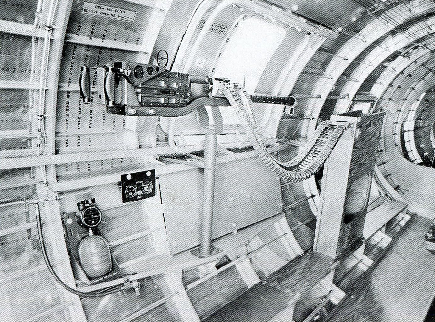
Factory photo of Station 6 aboard a B-17E. The layout here was factory stock for much of the B-17’s production, with the notable removal of insulation in the G-series. The first aid kit is not attached in this photo
Design aspects mentioned earlier are visible here, such as the never-used passenger seats, pyramid-type rubber matting, and the decal on the door indicating that it was to be open when using the hatch gun.
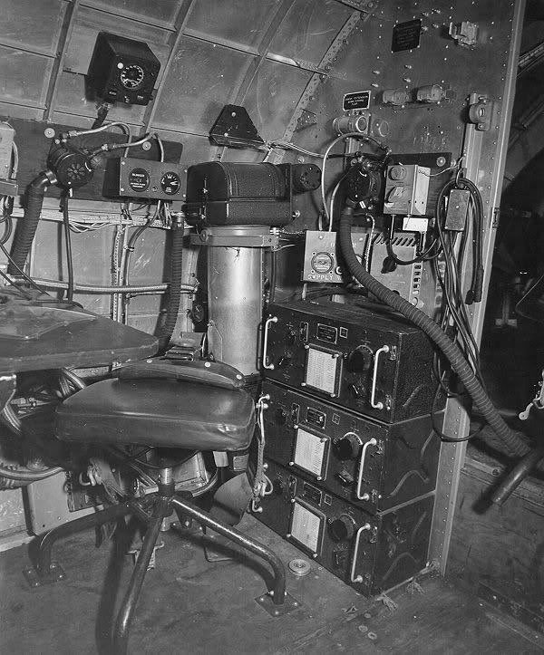
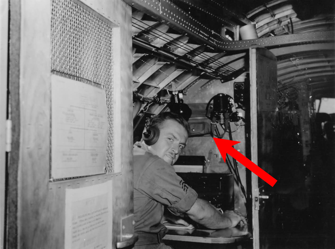
Photo showing the radar operator’s position aboard a Pathfinder B-17G. The radar operator’s station was fitted directly behind the command radios on Pathfinders.
There are many aspects of this photo applicable to our review of Monogram’s B-17. For example, take the truncated tuning unit stack. By the end of 1943, it was not uncommon for crews to start limiting the number of tuning units. After all, it was unlikely that aircrew would need every one on a single operation.
Also note the Cramer posture chair (mentioned earlier). This one has a folding back, which indicates that it was pulled from the bombardier’s position on a mid-to-late B-17F. Similarly, the rubber matting has been pulled and the radar operator’s work table painted dark green. The cushions on the posture chair are dark green vinyl.
The other side of Station 6 on the Monogram B-17 kit.
Despite prominent mold ejector pin marks, this area is relatively accurate for a typical B-17.
While shallow, the rectangular area on the left is actually a pair of shelves. The lower piece, undersized, is the dynamotor for the liaison transmitter on the other side of the wall. The upper piece is fictitious. In actuality, this was where the aircraft’s IFF transponder was mounted. Because regulation prohibited it from being photographed, relatively few photos survive which show this piece.
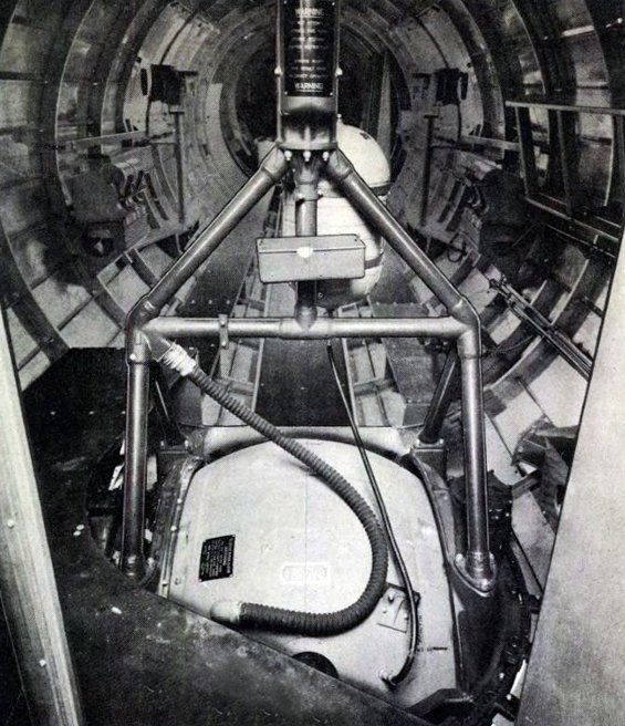
Manual photo of this position aboard an early B-17G.
Note the presence of the liaison transmitter dynamotor and the absence of the IFF transponder above.
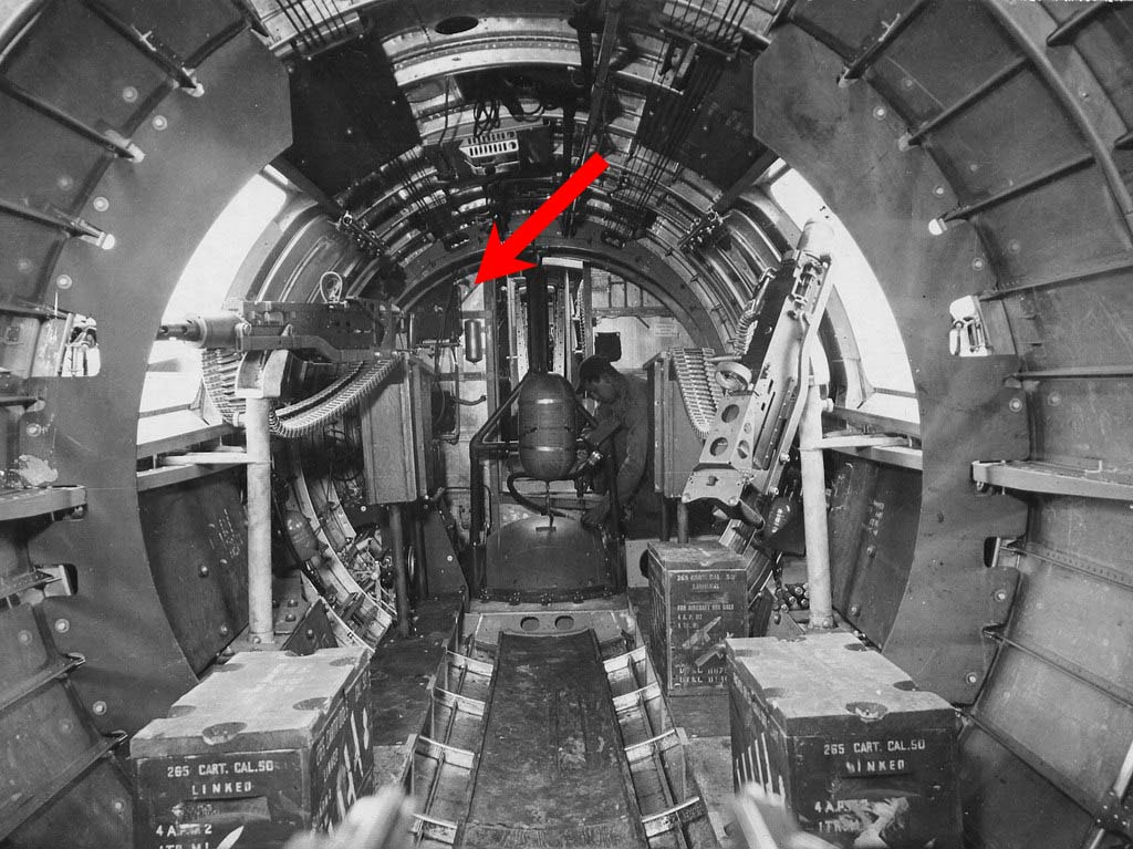
A rare photo of an IFF transponder installed aboard an early B-17F. Early-Fs left the factory with can-fed waist guns, and there were a myriad of field modifications to create belt feeds, like on the aircraft shown here. A factory solution was quickly found and standardized.
Just to the right of the transponder is a Bullard first aid can. This was unique to older B-17s and not present on the G.
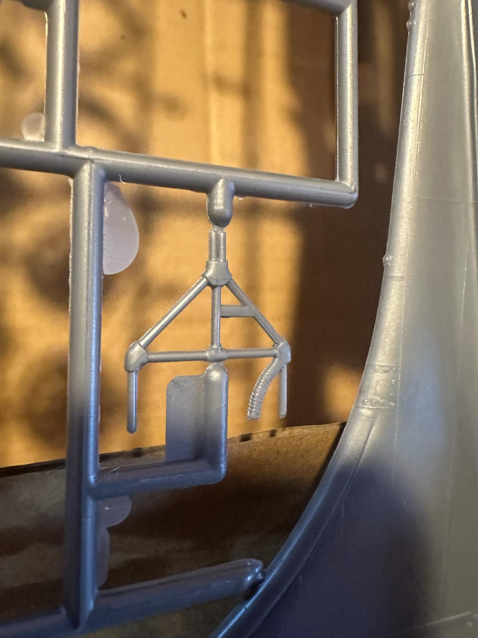
While the kit lacks the trunnion assembly, the frame for a Type A-2 Ball Turret is included in the Monogram kit. Once again, this is a feature more accurate to an F than a G.
The A-2A, visible in the Station 6 photo shown earlier, had a significantly lighter frame than the A-2. More importantly, the A-2A had a direct feed connecting the turret to the aircraft’s oxygen supply. The A-2 required its own oxygen tank. Despite this distinction, most modern restorations insist on attaching oxygen tanks to their A-2As.
I should perhaps note that the hose seen in the two reference photos is not an oxygen hose but the turret’s electrical conduit.
Ball turrets were designed by Sperry Gyroscope but manufactured by either Briggs of Detroit or Emerson Electric of St. Louis. Briggs-built turrets had gray interiors and olive drab hanger and trunnion assemblies. Emerson-built turrets used dark green.
It should be stressed that no wartime B-17 ever carried a ball turret with external ammo cans. This was only on the Type A-13A, which was used on late-B-24s and the short-lived B-32.
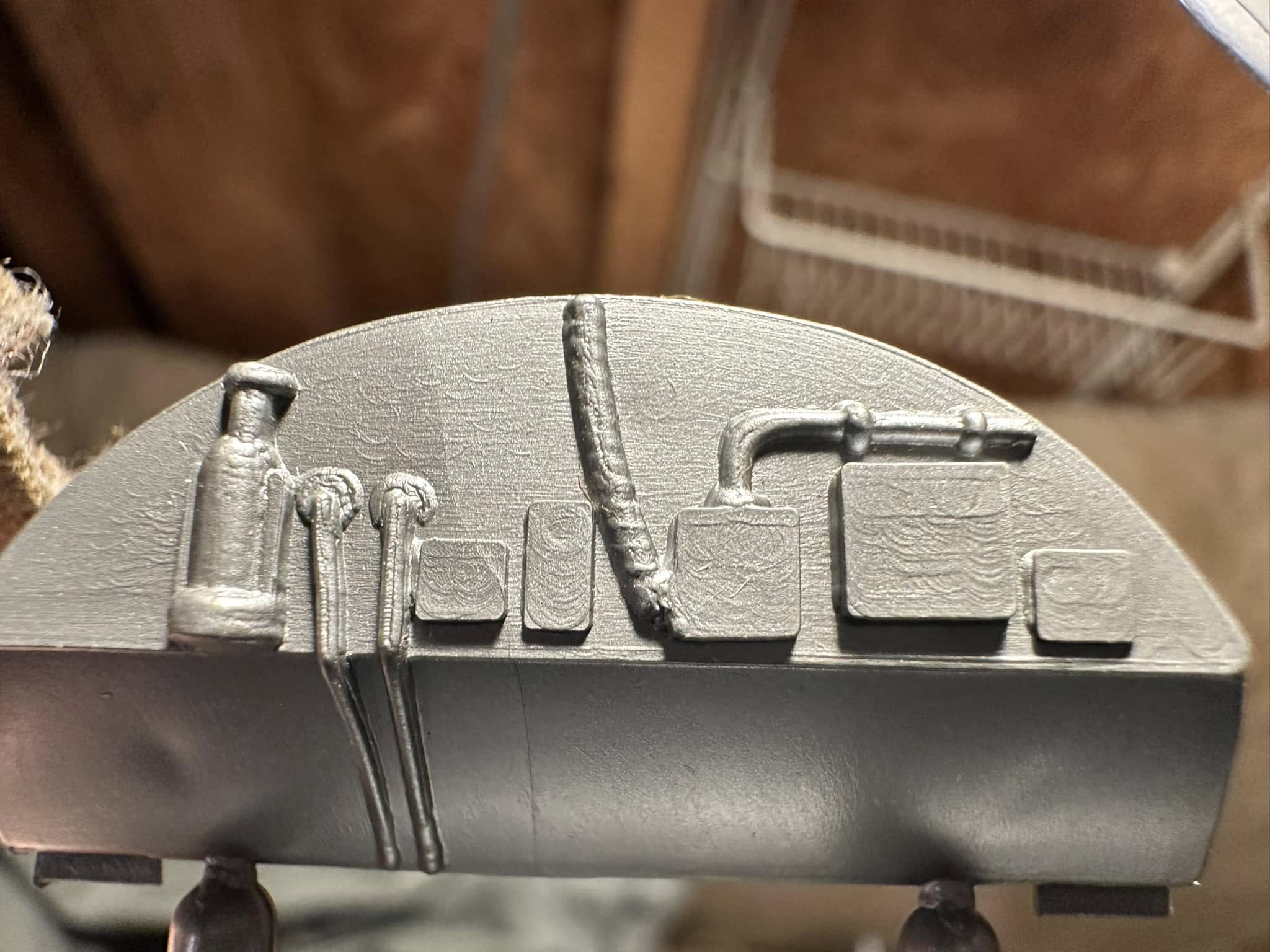
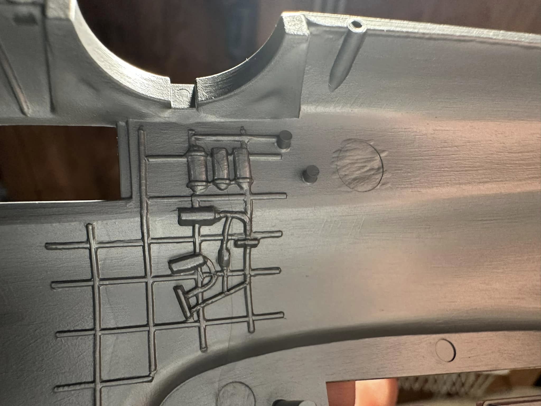
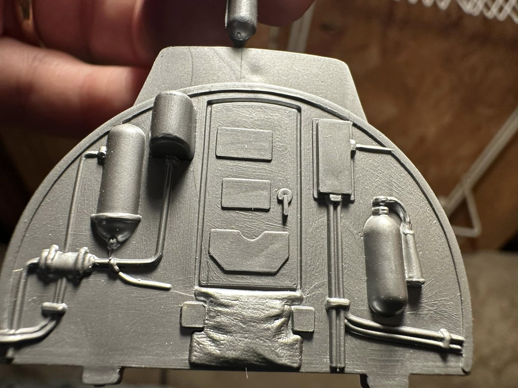
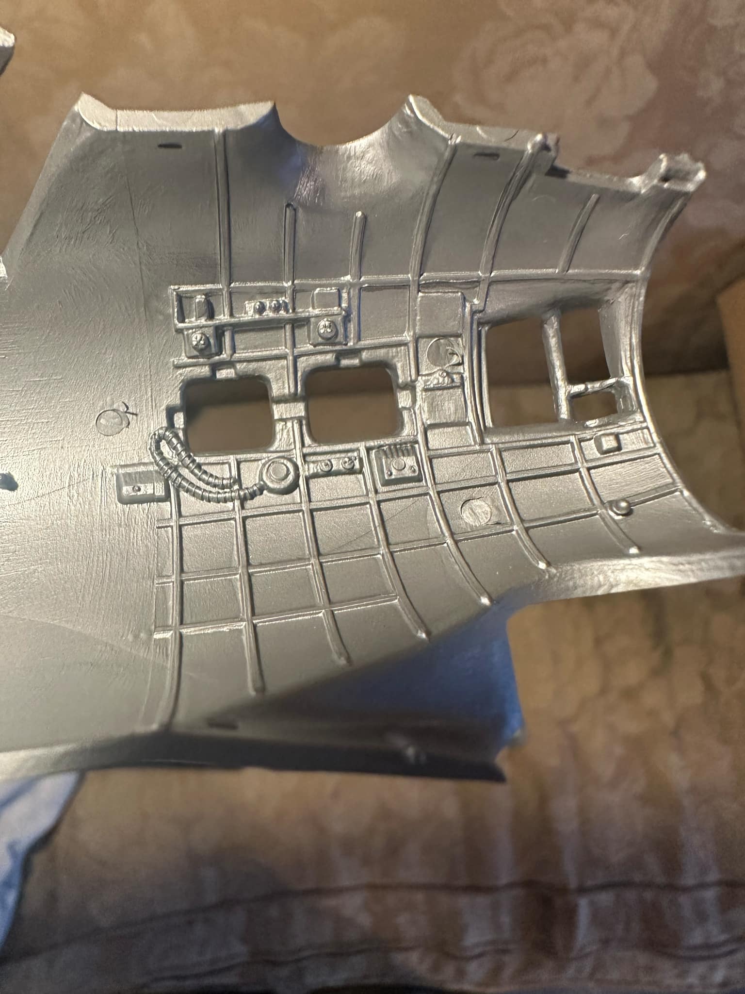
The Monogram kit’s representation of the upper half of Station 3, the back wall of the nose compartment.
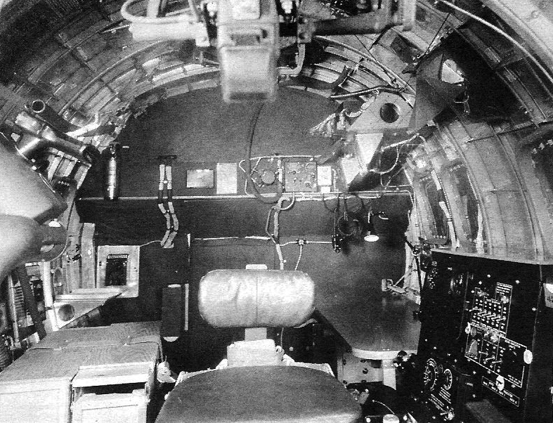
Factory photo of the nose of a B-17G. This photo is almost certainly the reference that Monogram used in creating the mold above. Unfortunately, in doing so, the parts are all out of scale, giving the impression of an area far busier than was actually the case.
The nose-side of Station 3 was insulated and covered with bronze green fabric. Once again, this was standard on all B-17s, regardless of variant. Up until the G-series, the entire nose compartment was fabric covered. On B-17Fs, modifications for installing cheek and nose guns were commonplace, and as a result, the outer layer of fabric forward of Station 2 (the halfway point in the nose) was often removed. This would expose the insulation underneath which, since the nose was tapered, was a green-covered, wavy diamond-stitch material rather than the more common bare, tube-stitched variety.
The piece to the far left is a brass carbon tet extinguisher. On this aircraft, the CO2 extinguisher for this compartment has been removed to make room for a sanitary cup dispenser (for defecating in).
To the right of the wire bundles is a small black box. This is a spare lamps box. Made of black plastic, these boxes did exactly what you might think – they held spare light bulbs.
The rectangle to the right of the spare lamps box is a placard for operating the radio compass system.
To the right of the placard is the navigator’s oxygen regulator, radio compass control box, and intercom jackbox.
Carbon tet. extinguishers restored for Lucky Thirteen by volunteer Chris Ely.
Photo taken 20 August 2024.
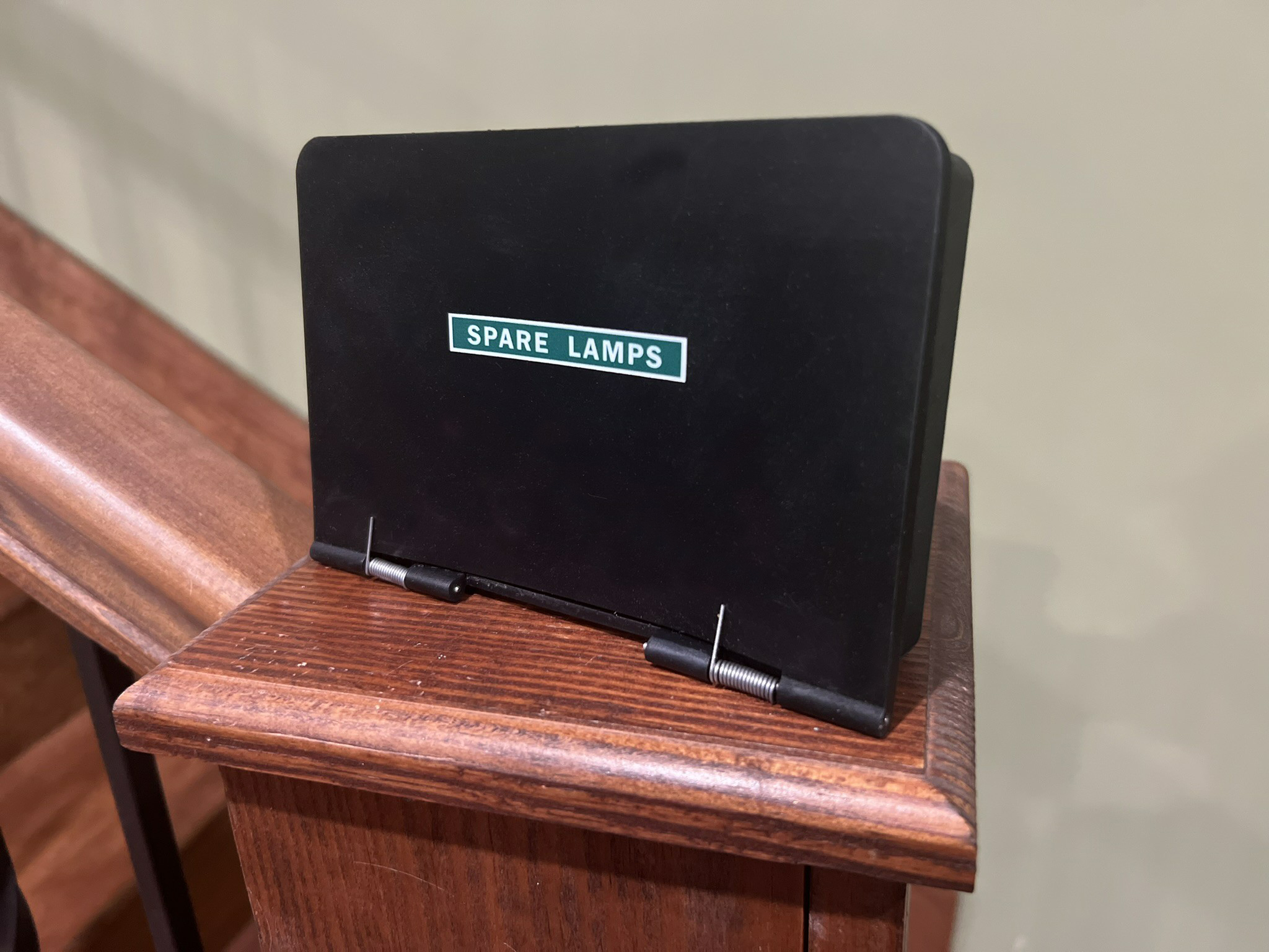
One of the three spare lamps boxes recreated for Lucky Thirteen.
Photo taken 3 April 2024.
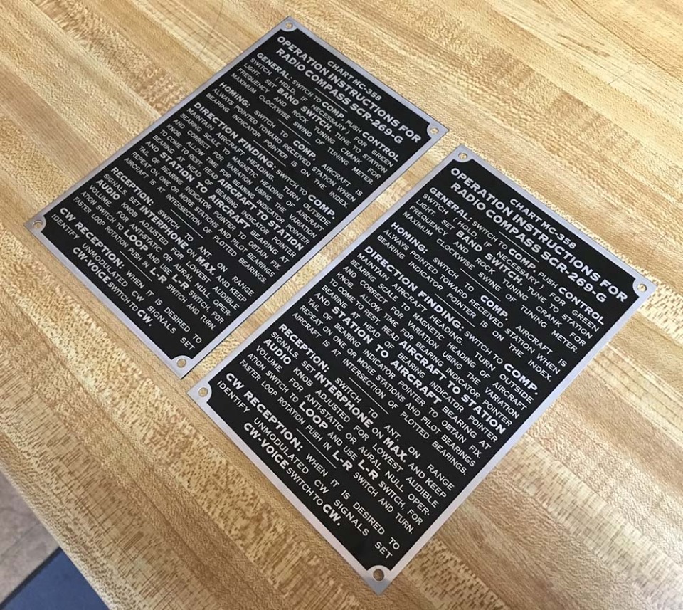
Instruction placards for the B-17’s radio compass system.
We recreated these plates for Lucky Thirteen, Desert Rat, and Memphis Belle.
Monogram’s representation of the left nose wall aboard the B-17G.
The layout here is pretty much accurate, with the exception of the shape on the far left side, which appears to be the nose compartment’s first aid kit. In actuality, this kit was kept in the same location on the opposite wall, though some aircraft kept the kit on the floor under the navigator’s table.
To the right of this piece is the navigator’s oxygen regulator and hose, oxygen indicator panel, and heated suit rheostat.
Between the windows is the bombardier’s clipboard, which is a fun touch. Above it is a square shape which could either represent the bombardier’s data card box or glide angles chart.
The dominating piece in this area is the large shape above the navigator’s windows. This is, in actuality, a shelf. Below the shelf were the indicator’s for the radio compass and fluxgate compass systems. On the shelf itself sat the fluxgate compass’s amplifier box. The shelf, as a whole, was unique to the G-series, but it should be noted that it did not remain on late-Gs, as it was replaced with a tall, vertical shelf for the GEE hyperbolic navigation system.
The bombardier’s data card box for Lucky Thirteen.
For fun, a bomb fuse safety pin has been dropped inside.
Photos taken 15 March 2019.
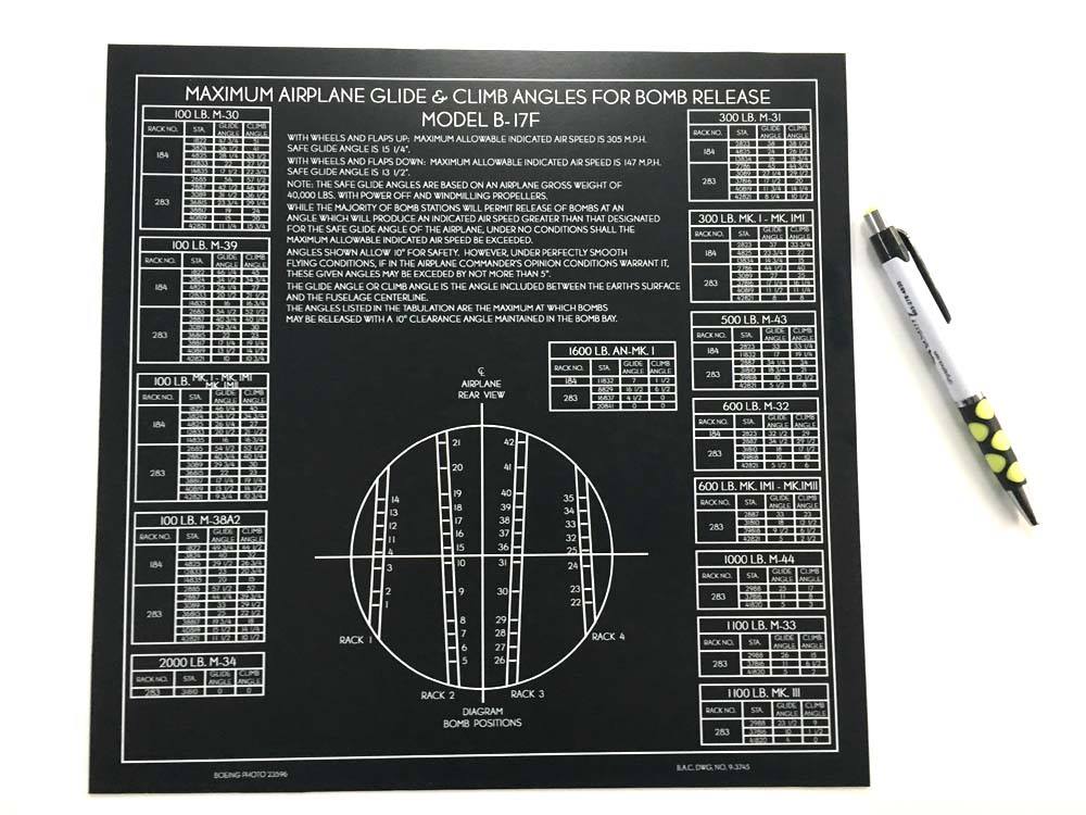
The bomb glide angles chart for Lucky Thirteen. The chart used on B-17Gs was almost identical to what you see here.
This chart, along with the bombardier’s data card box, was kept on the upper wall near the bombardier’s position, varying in location depending on cheek gun arrangement. On Es and early Fs, this piece was made of white cardstock, being much smaller and kept by the bomb bay door controls. We recreated this chart for Memphis Belle at the National Museum of US Air Force.
Photo taken 19 February 2019.
The navigator’s position aboard a B-17F.
Note that the shelf discussed earlier is not present on the F-series. Instead, the equipment is mounted on a series of frames attached to Station 3.
The navigator’s seat back here has been attached upside down so he can waddle on and off. Despite being the roomiest compartment on the B-17, it was not uncommon for bombardiers and navigators to remove the seats in this compartment entirely. Es and early-Fs, for example, had a bucket seat for the bombardier, which was despised for how much room it took up. The G-series saw the navigator’s posture chair mounted on a swivel attached to the desk, but this too was sometimes removed in favor of simply sitting on the floor.
It always seemed to me that Monogram lost an opportunity by not doing the nose compartment as a separate piece, then providing multiple nose variants for the modeler to chose from. Still, the kit’s layout is fairly typical of the B-17G.
Underneath the far right window is the aircraft’s drift recorder, though the shelf that it sat on is absent. The lens for this piece poked through the outside of the fuselage.
Starting from the right of the drift recorder, working its way down and over toward the nose, is the compartment’s heat duct. It terminated under the bombsight, blowing hot air onto the triangular glass window.
Regulators and oxygen hoses have been molded for the bombardier and right cheek gun position, the latter being one of three spaces on the B-17 for extra passengers.
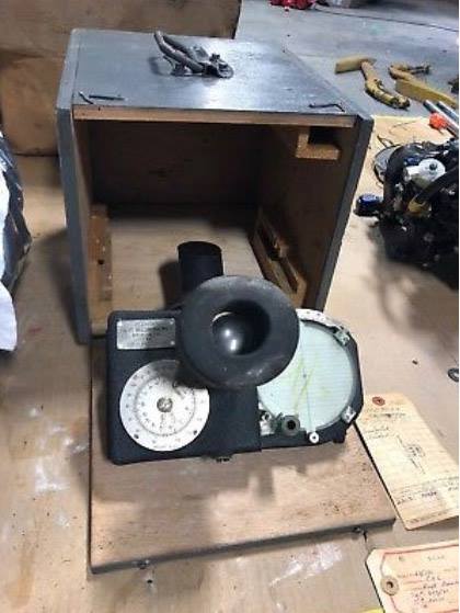
The drift meter for Lucky Thirteen.
Photo taken 26 September 2018.
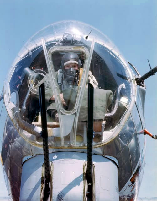
CPT Charles S. Hudson of the 91BG poses in this beautiful wartime color photo.
At the end of the heating duct was a flexible line, which made the final journey from the duct to the vent under the bombsight window. This was colloquially known as the ‘elephant pecker.’ Check your references, as some Gs inverted this vent to blow downward from above. The elephant pecker was not found on older B-17s, as not having the chin turret allowed the heating duct to pass under the bombardier’s seat and directly onto the glass.
Note that the bombsight is missing in this photo, its stabilizer obscured by a canvas cover. Norden bombsights were stored in lockers on the base when not in use. Likewise, only a handful of aircraft in each formation (lead and deputy leads) actually carried sights on a given strike. Many aircraft never got the chance to carry a bombsight throughout their entire combat career.

The Monogram kit’s flooring around the bombardier position.
The large object to the right are the two ammunition boxes for the cheek guns, strapped together. On B-17Gs, the chute for the left cheek gun passed around the front of the bombardier – a very difficult thing to model, even in photoetch.
To the right of where the bombsight attaches is the base of the chin turret control column. The chin turret’s controls were on a swivel and could be stowed away when not in use.
To the left is a large piece representing the bombardier’s control levers. The B-17 went through three major bomb bay control systems: one lever controlled, one cable controlled, and one entirely electric. The control column shown here crudely represents the cable-driven variant. Of the three types, this is the one that saw the least use, being only found on early-Gs. While accurate to what Monogram has modeled, it is still a curious choice. Then again, it is something that people tend to expect. Many B-17G restorations today include this control column even though aircraft with electric systems had no column whatsoever.
Factory photo of the bombardier’s position aboard a B-17G.
Note that this aircraft has no bombardier’s control column – this aircraft has an all-electric bomb bay system.
The chin turret control has been partially swung to the stowed position, though the sight assembly overhead shows that the turret is facing forward. Usually, the chin turret was turned all the way to one side when not on operations, so that ground crews could access its interior easier.
A rarely known piece of trivia, the round portion under the bombardier’s seat was clear plexiglass, so the bombardier could seen down inside the turret.
For comparison, a factory photo of the bombardier’s position aboard a B-17F. This aircraft has not yet been altered to fit a nose gun. The most common nose gun variant saw a single .50 cal. mounted to a triangular plate in the center of the nose. Ammunition for this gun was fed by a wooden box by the bombardier’s right side.
Note how there are no ammo boxes for the cheek guns. The layout for cheek guns on Fs varied considerably, and many of these variants could not accommodate belt fed cheek guns with ease. Aircraft like this one were equipped with 30 round ammo cans for these positions, stowing the cans for the left gun under the navigator’s desk and the cans for the right gun on the Station 3 bulkhead.
The removal of the outer fabric forward of Station 2, revealing the wavy-diamond insulation underneath this area, is visible here.
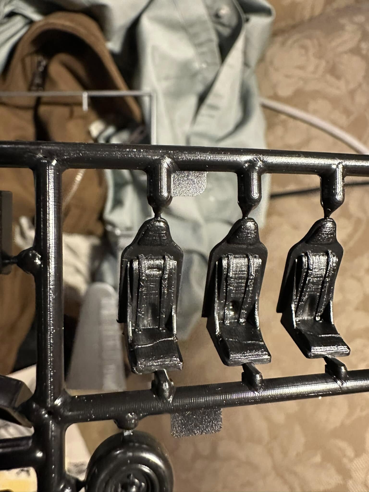
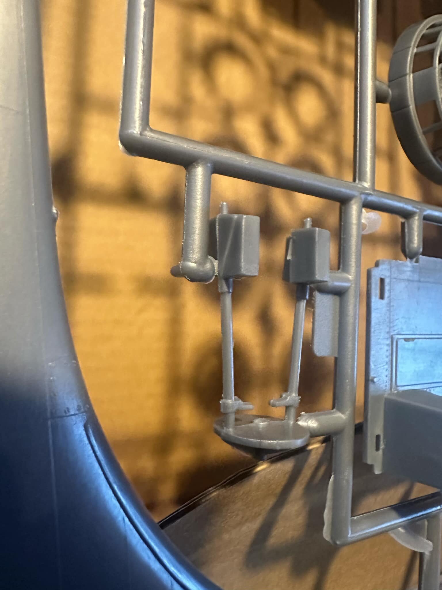
The Monogram kit’s representation of the B-17’s bucket seats. Rather than mold them as a separate piece, Monogram elected to model each seat complete with its armor plate attached.
The radio operator’s bucket seat was not identical to those in the cockpit, the primary difference being that the cockpit seats were painted bronze green while the radio bucket seat was unpainted. However, only early-F radio bucket seats had armor plates, and they were not nearly as large as those in the cockpit.
Speaking of armor plates, it is worth noting that the triangular shapes on top are not headrests but charts for the aircraft’s operating procedures. The cushions were yellow (as they doubled as floatation devices) and the shoulder straps, while technically accurate, were by no means common.
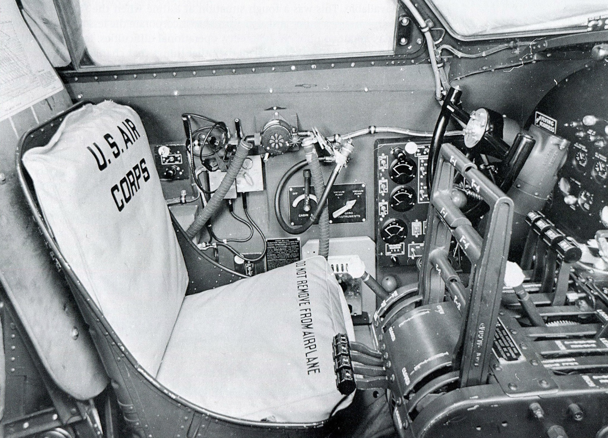
Factory photo of the pilot’s seat aboard a B-17F.
Note the difference in color between the seat and the armor plate behind. Armor plating was usually painted olive drab.
The layout of this position changed little between variants. Perhaps the most common error comes in the throttle column. Above the main throttle are two sets of four levers – on the left the turbocharger controls, and on the right, the mixture controls. The B-17G replaced the manual turbochargers with an all electric system, removing the four levers on the left and replacing them with a single, large black knob. B-17Fs did not have this piece.
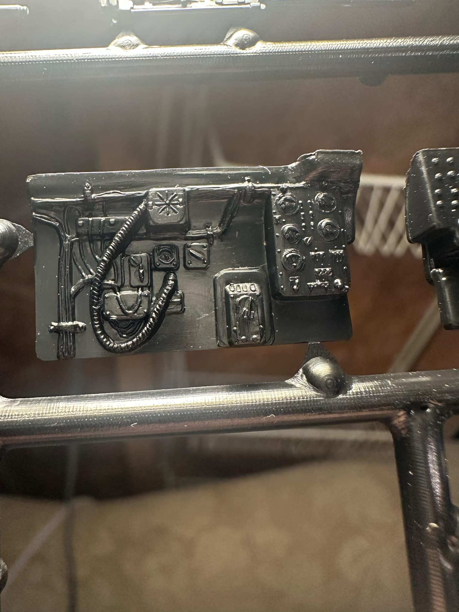
Since the previous photo showed the pilot’s left side, this is handy spot to go over Monogram’s version of this area.
Again, Monogram’s depiction is shockingly accurate. The only questionable bit is the rectangular piece at the upper left of the oxygen hose, as it is fictitious. From a modeling perspective, the only issue is that this piece is a continuation of the cockpit wall and not a separate panel. To be accurate, its outline would have to be blended to fit the rest of the cockpit’s insulation.
The oxygen regulator here has been molded in a square shape, with the correct circular shape being imprinted.
Below are the three boxes for the intercom jackbox, switch box, and filter, under which is another rectangular shape, representing the aileron trim controls. The trim control box is molded here rather than attached to the floor, for the sake of simplicity.
To the right is the pilot’s heated suit rheostat, which has a backing plate attached to keep the heat it generates away from the fabric.
And last is the pilot’s electrics control panel. This panel was typically painted bronze green rather than the standard black.
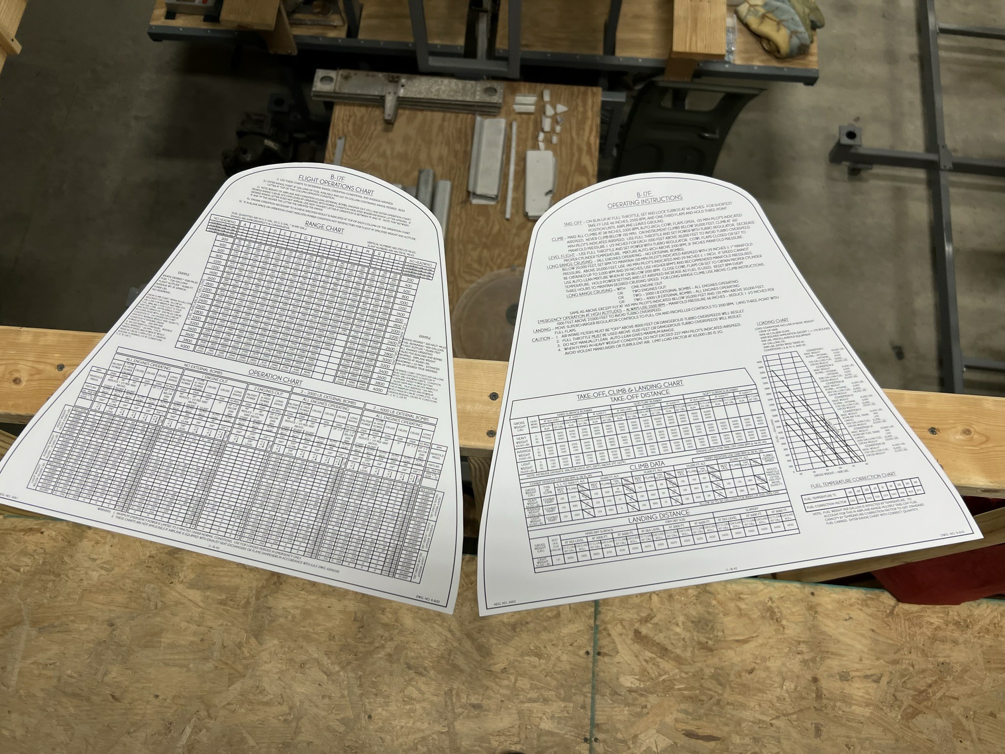
The recreated Operating Instruction and Flight Operations Charts for Lucky Thirteen.
Special thanks to Karl Hauffe who found the original prints for these back in 2019.
Photo taken 9 February 2024.
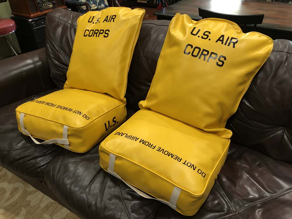
Pilot seat cushions recreated for Lucky Thirteen as a thank you for working on Memphis Belle. Truly one of the great honors of my life.
A later version of these cushions read “Army Air Forces” and had “US Army” written on the sides.
Photo taken 10 September 2020.
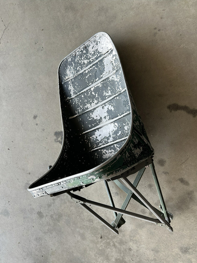
Lucky Thirteen‘s pilot seat, awaiting restoration.
Photo taken 28 June 2023.
Monogram’s representation of the copilot’s right side.
Once again, this is very well done.
The large box on the far left is the co-pilot’s auxiliary panel, which included the engine starters and carburetor controls. Up until partway through the F-series, the carburetor controls were on the main panel. Below this panel sits the intercooler controls. As with the trim box on the left side, these pieces are molded here for the sake of simplicity.
Again, the oxygen regulator is molded square with a circular outline pressed in.
Under the oxygen hose is the copilot’s heated suit rheostat along with its backplate. Here, the backplate also includes a second radio compass instruction placard. Below this is the T-handled engine primer pump.
The copilot’s intercom boxes are partially obscured by the handle for the hydraulic handpump. Above the handpump is a square shape representing the copilot’s panel light. This piece is oversized.
Manual image showing the right side of the copilot’s position. This area remained largely unchanged throughout the B-17’s production.
One often unnoticed aspect of the B-17’s cockpit – the aluminum floor around the pilots’ feet was left unpainted.
The left waist position as depicted in the Monogram kit.
In general, this depiction is accurate for the majority of Fs and early-Gs. The only real inaccuracy is the oxygen bottle shown on the far right, which is fictitious.
Underneath the bottle is the assembly for the aircraft’s reel antenna. This unit could be spooled out from the airplane to gain stronger radio signal.
Above and below the window are sections of armor plate, typically painted olive drab. To the right of the lower plate are the waist gunner’s oxygen panel, intercom jackbox, and below, heated suit rheostat. Depending on variant, the latter two pieces were often mounted overhead.
The two rails below the gun are meant to represent sections of flooring to brace the gunner when firing his weapon. The ProModeler edition of the kit included extra pieces to better represent the lower portion.
On aircraft with three-part waists like this one, the floor was composed of a curved center walkway, with flat sections of bracing walkway on either side. While made of wood (starting in the middle of the F-series), this area was delivered with pyramid rubber matting. When the B-17’s waist was redesigned in the G-series to stagger the waist guns, the three-part floor was replaced with a larger, flat design.
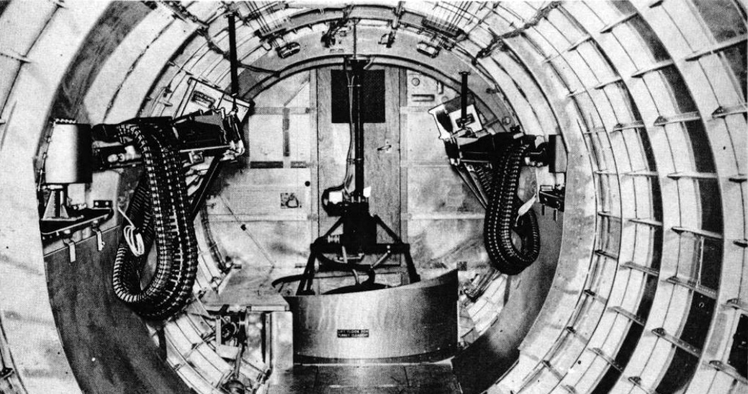
The right waist position of a late B-17F.
The three-part floor can be seen here, with the pyramid rubber matting removed. The object to the left of the oxygen indicator panel is one of the aircraft’s thirteen portable oxygen bottles. This type, the Type A-4, was replaced by the Type D-2 partway through the G-series. The D-2 was a long, yellow bottle that, while cumbersome, provided a great deal more oxygen. With the exception of Shoo Shoo Baby, the D-2 is the correct walkaround bottle for all surviving B-17Gs today.
Note the coloring of the fuselage walls – this is perhaps the most frustrating aspect of B-17 inaccuracies we run into. B-17’s did not have painted interiors. The only compartment that was consistently painted was the cockpit, its equipment being painted bronze green or, later on, dark dull green. There was admittedly a little variation between manufacturers regarding the use of zinc chromate primer, and it should also be noted that aircraft pulled from mothballs, as well as all US Navy PB-1Ws, did indeed spray their interiors green. Still, as a general rule, B-17 interiors were unpainted.

The same position, this time aboard an early B-17G.
Note the serial number painted on the back of Station 6. This was a characteristic of B-17s built by Lockheed-Vega.
Also note that the E-12 gun cradles, which used a spring-based recoil system, have been replaced with hydraulic E-11s now that the position is enclosed.
The three panel waist window, characteristic of early-Gs, featured two flat outer panels and an angled center panel. The center panel was angled toward the tail, taking into account the physics of fighter pursuit curves.
Manual illustration of a late-G waist section, with the staggered waist guns and single panel floor. The windows here are made of solid sheets of plexiglass.
Note the presence of the protective shield in front of the ball turret, a piece often found on later aircraft.
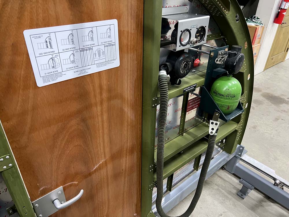
The bomb bay side of Sta. 5 for Lucky Thirteen.
Note the Type A-4 Walkaround Bottle and its bracket. Lucky Thirteen still needs more A-4 walkaround bottles, Q-1A rheostats, and Pioneer A-12 oxygen regulators, so if you can be of help here, please let us know!
The chart on the door contains instructions for loading various bomb types. While the recommended weight was 4,000 lbs, the B-17 could accommodate up to 6,000 lbs internally.
A pair of external racks, inboard of engines 2 and 3, could carry an additional 8,000 lbs, though these racks were rarely used as they greatly affected performance.
Photo taken 11 January 2023.
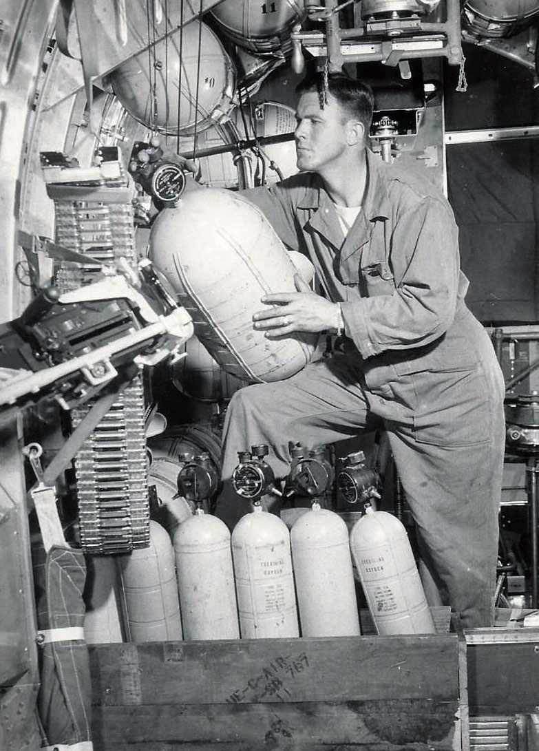
While this photo was taken aboard a Consolidated B-24, it is still worth sharing as the box at his feet is full of Type D-2 walkaround bottles.
These were used on the overwhelming majority of B-17Gs.
All in all, I think that about covers the major details of the Monogram kit.
The only other thing that comes to mind as worth mentioning is an external detail –
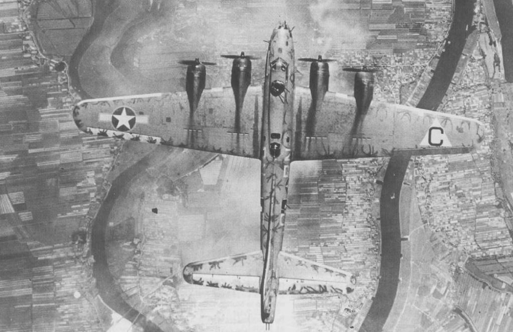
The 1990 film Memphis Belle gave rise to the belief that the four slots behind each engine were part of the aircraft’s exhaust. They were not. They were merely air vents.
The aircraft’s engine exhausts were actually located underneath the wings, leaving dark stains behind each of the engine turbochargers. The light staining above the wings was caused by engine oil. And, interestingly enough, the vents tended to clean away the staining behind them.
The rotation of the props, combined with the air flow pulling toward the fuselage, created an interesting pattern. Using the photo above as an illustration, the props are turning to the left. The wake of the props pulls left, while the air flow pulls toward the fuselage. As such, there is a slight angle behind no. 1, virtually no angle behind no. 2, a stronger angle behind no. 3., and an extremely strong angle behind no. 4. This was typical.
If you enjoyed this article, please consider supporting our work on Lucky Thirteen.
The Hangar Thirteen Foundation is a 501c3 nonprofit based in Asheville, North Carolina. We have no wealthy benefactor but are nevertheless uncompromising in our dedication to accuracy. Contributions toward the project are tax deductible and you can guarantee that fruits of your involvement will be seen here online. Financial donations help more than you can imagine, but for those uncomfortable or unable, we try to be open about the parts we need as well. Should you have a part you would like to contribute, just contact us. If you wish to donate, you can do so via PayPal using the Donate link. Or, if you would like to avoid PayPal taking its fee, you can send a check to Hangar Thirteen. Because we will soon be changing locations, we recommend my home address at:
Gerad Allen Blume
442 Old Chalk Bed Road
Batesburg, SC 29006
Everything we have accomplished thus far has been due to the support of those who believe in us. To those who have contributed before, we cannot thank you enough for the support you have given us. We hope we do you proud as we continue our efforts to properly honor the past.
Keep the show on the road and happy modeling!