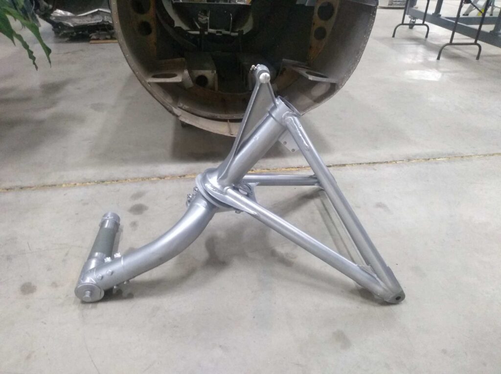
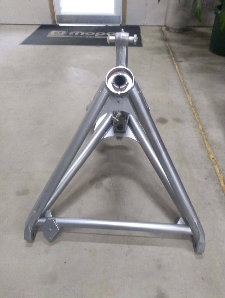
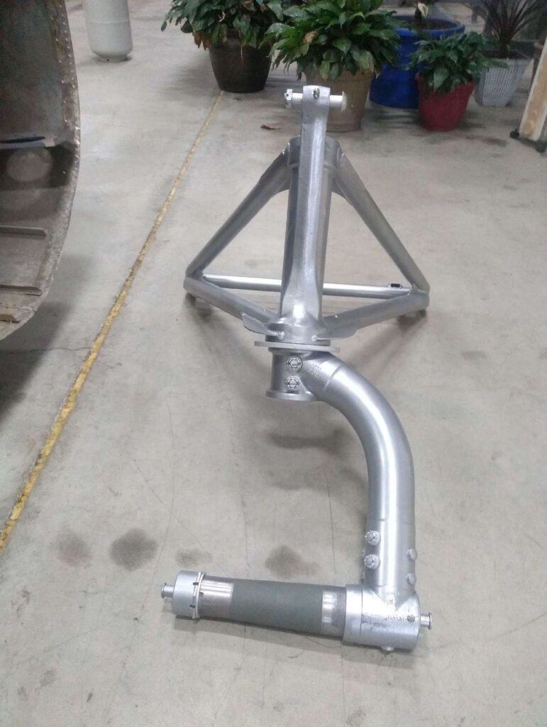
We now have the co-pilot’s yoke column for Lucky Thirteen!
To recap, we were given the opportunity to purchase a yoke column from a Boeing B-17F last month. Said piece was rather expensive, but you never know if you never try, so we presented the piece to our supporters. It was a long shot. The more we accomplish on Lucky Thirteen, the rarer and more expensive parts get, and we understand the frustration of having to be vague, just to keep others with deeper pockets from scooping up opportunities from under us. Thankfully, our supporters stepped up, raising the funds within days. It was absolutely incredible! Words cannot express how thankful we are for everyone’s support.
To go into more detail about the yoke column’s origins:
This is the co-pilot’s yoke column from Charlene (42-30177) of the 388BG. Charlene participated in 18 combat operations between 17 July and 13 December 1943. Two of those missions she flew alongside Lucky Thirteen, the latter being the strike of 6 September when Lucky Thirteen was shot down. On 19 January 1944, Charlene was transferred to the 803BS (P), later redesignated the 36BS, the 8AF’s dedicated radar countermeasures unit. One of the last Fs on active duty by that autumn, the bomber was converted into a VIP transport for the French, beginning with a round-the-world tour from 6 September through 1 October 1945. She was presented by CG SHAEF GA Dwight D. Eisenhower to Général de Corps d’Armée Marie J. Pierre F. Koenig as a personal transport on 17 December 1945. Koenig served as the military governor of the French Occupation Zone of Germany from 1945 to 1949. Famed for his role in the Battle of Bir Hakeim in North Africa, the B-17F was renamed Bir Hakeim in Koenig’s honor.
The old bomber was acquired by the Institut Géographique National in 1953, commissioned by the postwar government to photograph and map France and its colonies, covering some 6.18 million square miles. A small collection of B-17Gs were purchased for this purpose and Bir Hakeim, already being French property, was kept as a source for spare parts. She was ultimately scrapped in 1973.
Undoubtedly, there are other parts from Charlene floating around out there in collector’s circles, including the pilot’s yoke column. Who knows? Maybe these parts can find their way here as time goes on.
Original B-17 yokes were made of cast aluminum coated in hard rubber. The rubber on this example is badly cracked in places but we have already begun looking into having it professionally restored. Longtime Hangar Thirteen supporter Todd Blalock of Decatur, Alabama was kind enough to provide us with a replacement push-to-talk switch, as the original was frozen with age. The plug for the opposite side is missing and will have to be replaced or reproduced.
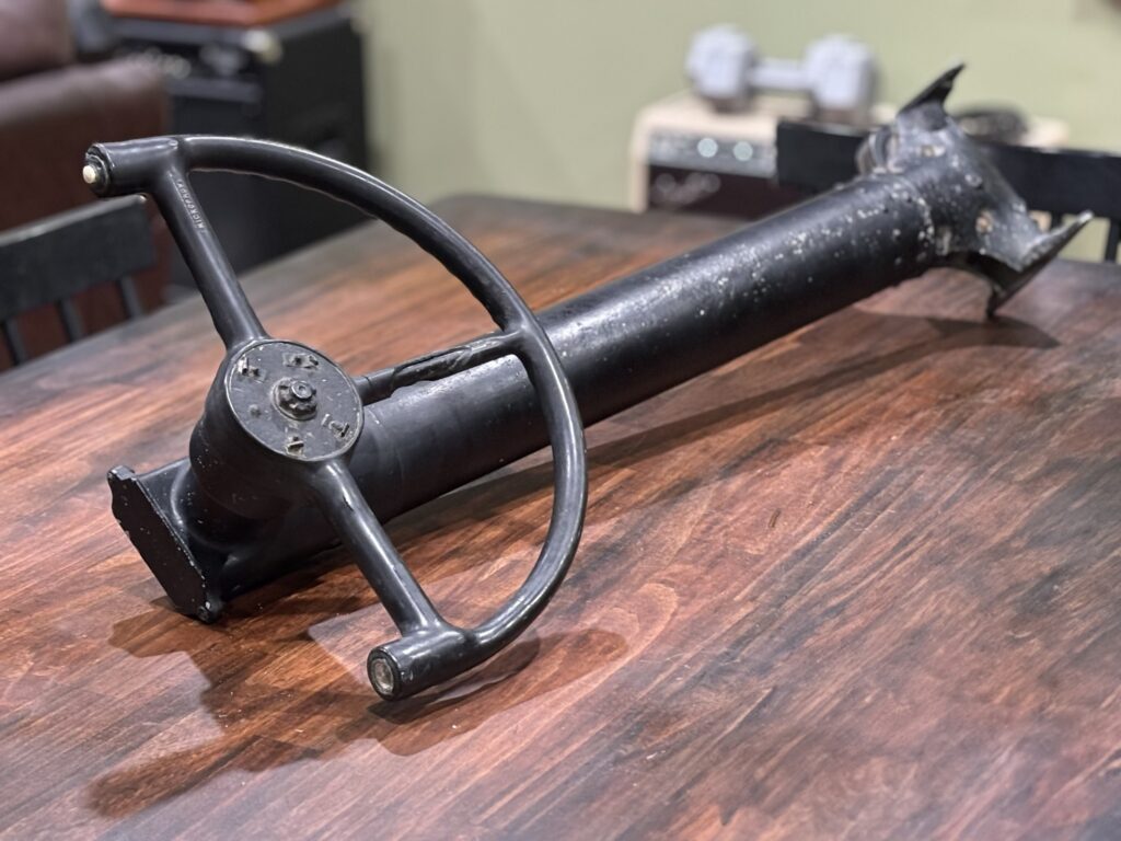
The newly arrived yoke column from Charlene (42-30177, 388BG).
At some point in its history, somebody brush painted the assembly black.
Photo taken 19 July 2024.
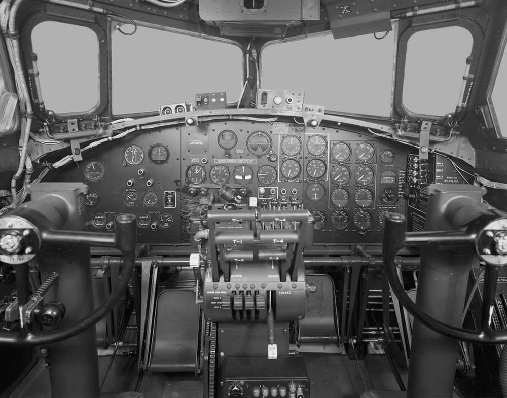
The cockpit of an early B-17G.
Note how the inside grip of each yoke has a plug. The outside grip of each yoke has a push-to-talk switch.
Photo taken 9 February 1944.
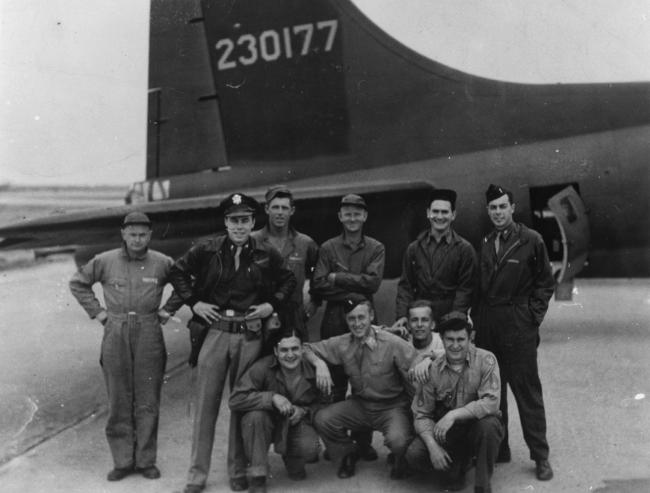
The crew of Charlene shortly after arriving in the ETO. Though the photo is unlabeled, the airman with the sidearm appears to be 2LT Charles C. Bliss. The name Charlene was in reference to his daughter.
The aircraft’s identification markings have not yet been added, which included the Square-H group insignia and recall letter F.
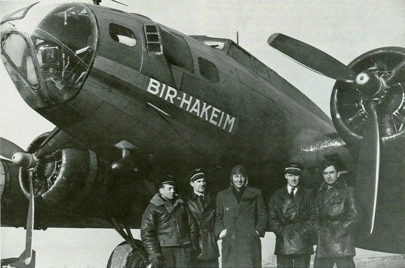
Bir Hakeim in service as General Marie J. Pierre F. Koenig’s personal transport.
Her paint was stripped in 1950 shortly after retirement from transport duty.
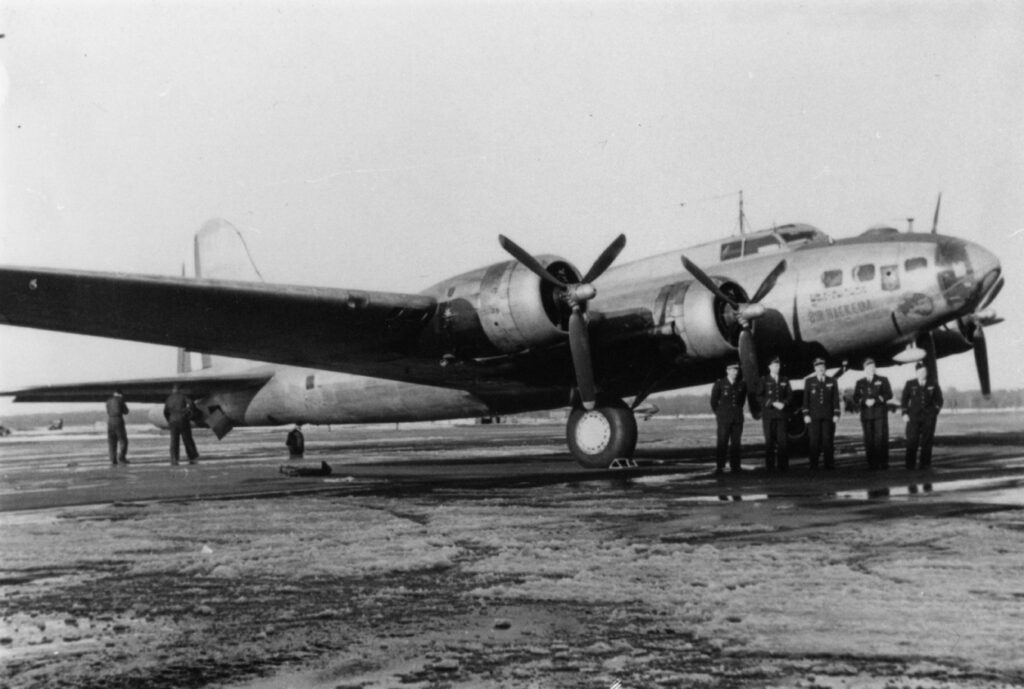
Bir Hakeim with her paint removed.
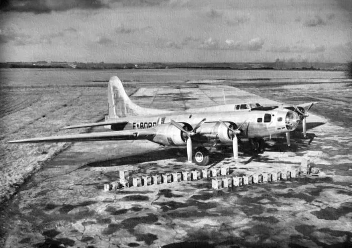
44-85594, one of the fourteen B-17s acquired by the IGN for cartography duties, poses with a set of camera glass cases.
Of the fourteen, five were scrapped in 1973, with another two being lost in previous accidents. An additional IGN B-17G was lost during the filming of the 1990 film Memphis Belle. The remaining aircraft are today’s Thunderbird (44-85718), Mary Alice (44-83735), Sally B (44-85784), Pink Lady (44-8846), and Shoo Shoo Baby (42-32076). The latter two are combat veterans.
Charlene, the third combat veteran, was the only F of the group.
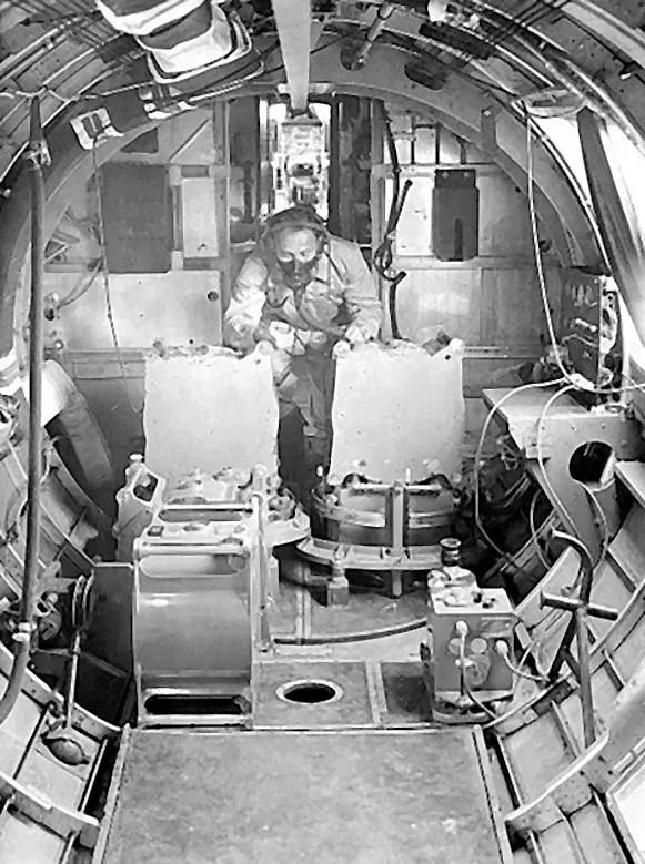
A photographer at work aboard one of the IGN B-17Gs.
Note the sanitary cup holder on the right wall, staggered waist windows, and heating duct above the waist – all features unique to B-17G.
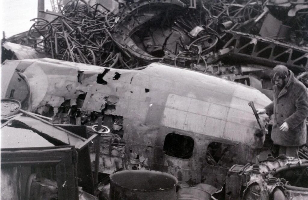
Charlene sitting in the scrapyard.
If anyone has the pilot’s yoke column and would like to see it go to a good cause, please let us know!
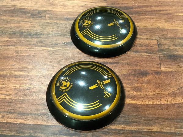
A pair of yoke caps donated to Hangar Thirteen by Luke and John Matthews of West Yorkshire, England.
Their granddad was Arthur Matthews, who served in Italy during the war with the 43rd Commando (Royal Marines). Arthur brought back these yoke caps as souvenirs, leaving them to his son Alan after his passing in 1978. Alan passed away last year, leaving the caps to his sons. We are truly humbled and honored that they chose to donate them to Lucky Thirteen.
Aircraft manufactured under license by Douglas and Vega featured this style of yoke cap, with the licensee’s logo appearing in the corner. These attached to a clip with a turn-lock. The Boeing style cap was held by tension locks. Charlene, being a Boeing built aircraft, still has the tension locks on her yoke column.
Photo taken 19 April 2021.
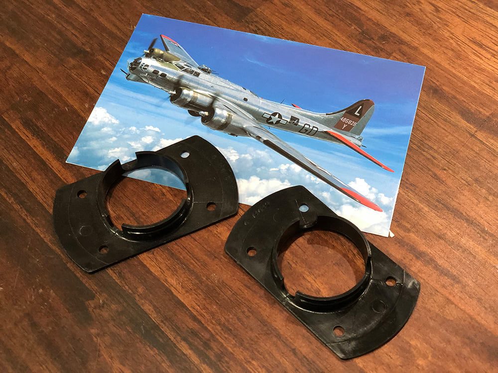
A pair of yoke cap attachment plates, donated by the Yankee Air Museum in February 2021.
Photo taken 19 April 2021.
I wanted to share something that I find fascinating.
As regular followers are likely aware, we are good friends with the team at Planes of Fame Air Museum working to preserve and restore the Boeing B-17G Piccadilly Lilly II (44-83684). The history of this aircraft is truly fascinating. Like most survivors, she was built too late to see combat. Instead, she was used as a drone controller for Surface-to-Air (SAM) and Air-to-Air (AIM) missile testing. In fact, she holds the distinction of being the last B-17 listed as active-duty US military, retiring on 6 August 1959.
I got a text from Steve Salinas on 13 July about a mount they found in the aircraft’s nose. The guys had recently removed the flooring in the nose compartment so that it could be refinished, as well as to replace the nut plates which hold the Type A-16 Chin Turret. The mount they found is rather interesting; I will explain why…
The mount is for the whip antenna on the SCR-269 Radio Compass, better known as the Radio Direction Finder or RDF. The RDF was simple but effective in its design. The idea was that you would tune the radio to a known frequency, after which the system would point in the direction where the signal was coming from.
Outside the disappearance of Amelia Earhart, perhaps the most famous example of an RDF system in use comes from the opening of “Blitz Week” – the incendiary bombing of Japanese cities by the US 20AF from 9 March through 18 March 1945. 334 Boeing B-29s, led by CG 314BW BG Tommy S. Power aboard Snatch Batch (42-65302, 29BG), approached the Japanese capital on the first night by homing their systems to Radio Tokyo. That night, the bombers burned to death some 83,793 people while the radio played with ironic morbidity “I Don’t Want to Set the World on Fire” by the Ink Spots. This was the deadliest bombing operation in human history.
An invaluable navigation aid, the RDF had a pair of controllers: one by the navigator’s position, and the other above the pilots. The primary antenna for this system was a large hoop, with the SCR-269 variant famously using a large football-shaped housing to protect the antenna. The mount that the guys at PoF found was for the system’s secondary antenna, a long 52.44 inch whip.
Now, here is where it gets interesting.
In 1944 the SCR-269 was replaced by an upgraded version called the ARN-7. The SCR-269 operated on a set of three bands, ranging from 200-1750 KC. The ARN-7 expanded that range to include a fourth band, covering 100-200 KC, as well as a CW/Voice switch. At first glance the control boxes look much the same, so it is not uncommon to see the latter system installed on restorations of aircraft too old to have carried it.
However, the most glaring difference is the secondary antenna. The ARN-7 replaced the long whip, which was easily damaged, with a wire pulled between two posts. This was common on B-17Gs and Piccadilly Lilly II did in fact have the ARN-7 installed. The guys even managed to find the original mounting holes for the ARN-7’s secondary antenna, along with the antenna posts comfortably set aside in storage.
So, why did they find the mount for the whip? Well, it turns out, there is no hole underneath the mount. The mount had been installed early in construction, before the decision was made to switch systems. So, they just left it there.
Details like that are fascinating to find.
Lucky Thirteen, being an F, had the older, SCR-269 RDF installed, complete with the whip antenna. So far, the only B-17 preserved today with this antenna is Memphis Belle, on display at the National Museum of the US Air Force. Since it is unlikely that an original will be forthcoming, Kenneth Wade in Muscle Shoals, Alabama has offered to recreate this piece. Along with the tuning cable for the Gyro Fluxgate Compass, these are the only components yet located for the bomber’s radio and navigation systems.
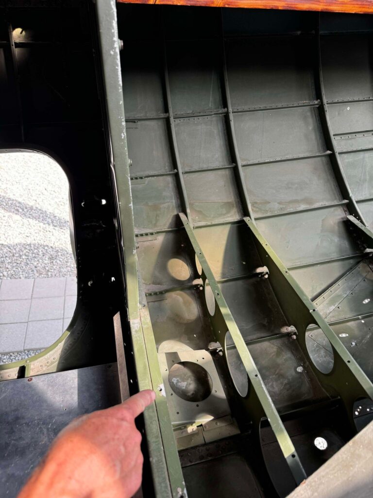
Steve points at the unused whip antenna bracket under the nose floor of Piccadilly Lilly II (44-83684).
Photo taken 13 July 2024.
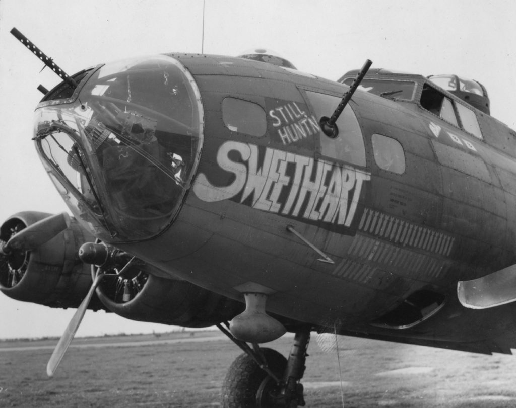
Sweetheart (42-3262, 388BG) while stationed at RAF Knettishall.
Note the whip antenna just aft of the football antenna.
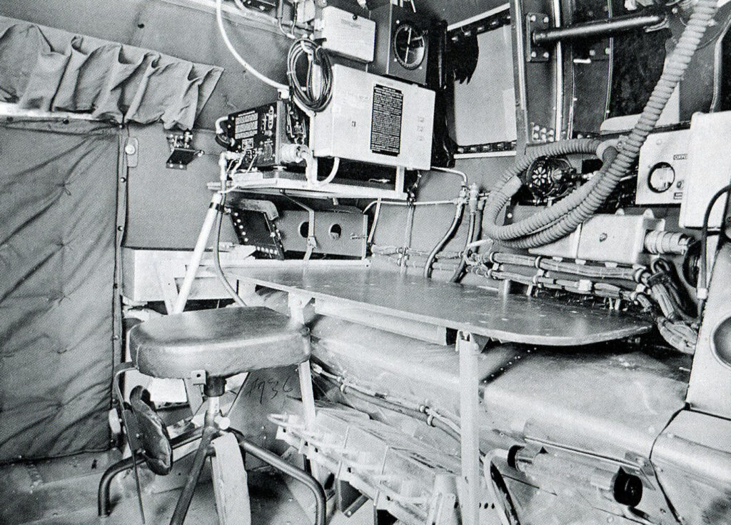
The navigator’s position aboard Flak Dodger (42-29467), an F with the 99BG.
The line running from the main unit of the SCR-269 (the BC-433) can be seen running down beside the navigator’s chair into the floor.
Note that not only is the table a modification from the United Airlines Modification Center in Cheyenne, Wyoming, but that the chair back has been attached upside down to make it easier to waddle on and off.
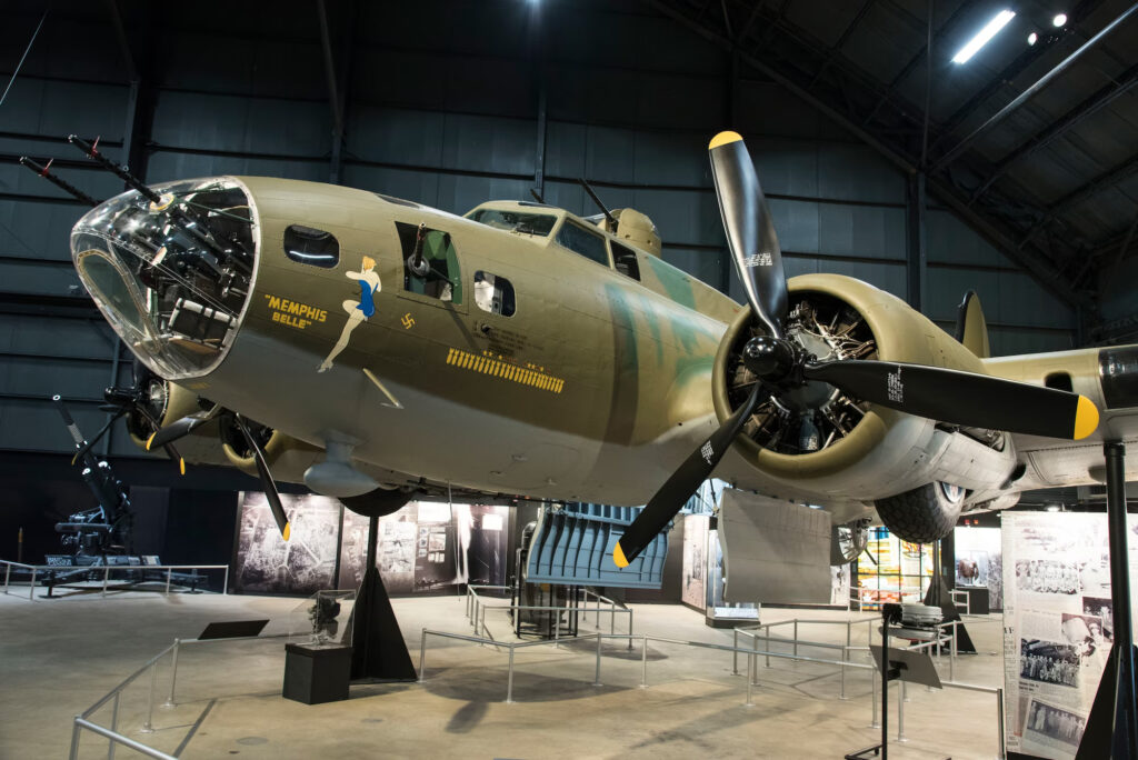
Memphis Belle (41-24485, 91BG) on display at the National Museum of the US Air Force.
Though barely visible, this is the only surviving example of the older whip antenna that we know of.
Since it is unlikely that another original will appear, we are working with volunteers to recreate this piece for Lucky Thirteen.
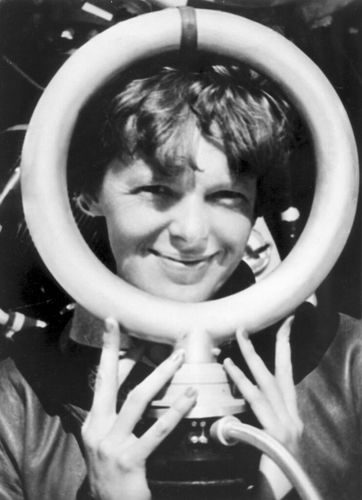
Amelia Earhart poses with the loop antenna from the Bendix RDF installed on her Lockheed Electra.
Some have speculated about the RDF’s role in her disappearance, suggesting unfamiliarity with the latest variant, or a possible unit failure.
Later variants placed the loop antenna inside a football shaped housing.
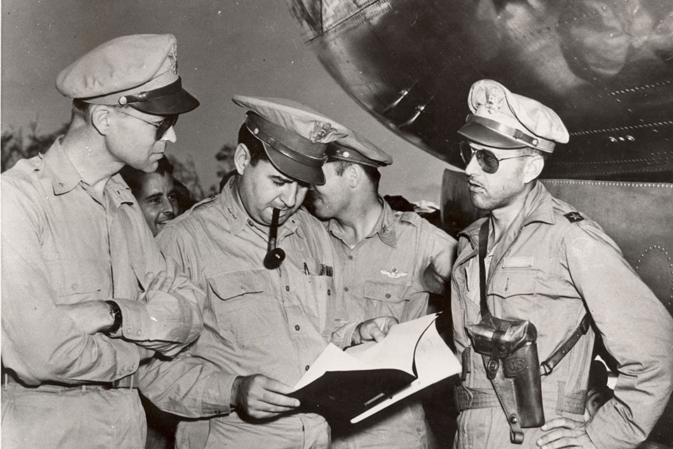
CG 314BW BG Tommy S. Power (right) with CS 20AF BG Lauris Norstad (left) and CG XXI BC MG Curis E. LeMay (center).
This photo was taken the morning after the 9 March 1945 strike on Tokyo.
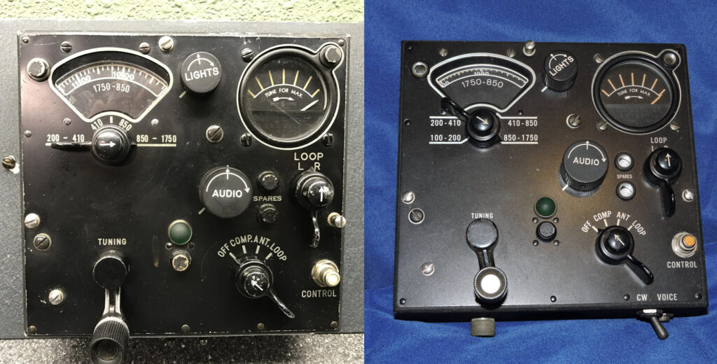
The controls boxes for the older SCR-269 RDF and later ARN-7 placed side-by-side.
The older box was the BC-434, while the latter was the C-4. The former was more prominent on wartime aircraft, by far.
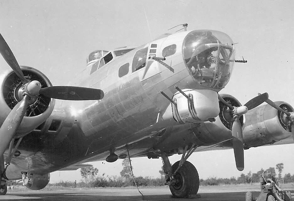
A Boeing B-17G with an ARN-7 RDF installed.
Note the new position of the football antenna and how the whip has been replaced by the line between two posts.
I thought I might talk about the tail gunner’s seat assembly here. We recently finished four. Three of these seats will be going to the UK, with one going to someone I’m sure most of you know – our friend Dave of the B-17 Cockpit Project
The B-17’s tail gun position was a genius design. Contrary to popular belief, US Army airpower theory prior to the war was not based on the idea that the bomber could defend itself. Rather, it was based on the idea that the bomber could attack its target and egress before fighters could locate and intercept it. Radar changed that. And reports from American observers in the UK – namely, one by LTC Grandison Gardner and MAJ Franklin O. Carroll filed on 1 July 1940 – argued that not only was investigation into long-range escort necessary, but that bombers also required turrets capable of defending the aircraft from all four axis.
Responses were slow as manufacturers struggled to solve the complex problems contained therein. While not a turret but a barbette, Boeing’s new tail gun, introduced on the B-17E, utilized a reshaped vertical stabilizer originally designed for the 307 Stratoliner. The gunner sat on his knees, his chest up against a .3125” armor plate – one sixteenth thicker than the standard .25” armor at the other positions. The main window was also bulletproof glass, measuring 2.5” thick. Since the majority of fighter attacks came from behind, the tail gunner also had the unique distinction of being the only airman on the B-17 to have an extra oxygen hook-up.
The B-17 tail gunner’s seat has sometimes been referred to as a bicycle seat, with some going so far as to suggest that it was made by a bicycle manufacturer. It was not. The seat might be more accurately described as a tractor seat on a miniature ironing board. An angled box assembly is connected to the airplane by a pair of springed levers. The vertical lever adjusts the position of the seat in relation to the guns, sliding it forward and backward. The horizontal lever adjusts the pitch of the seat, angling upward to help take the pressure off the airman’s knees.
From the B-17E up through B-17F-70-BO (roughly March 1943), the seat assembly was made of aluminum. Like the ammo boxes nearby, the tail gunner’s seat was then worked to be made of wood. The design changed little throughout the rest of the B-17’s run, though the seat’s forward hinge was altered in December 1943 to a somewhat stronger version. As is typical on the B-17, the plywood was Douglas Fir and the stiffeners Spruce. Interestingly, a variety of plywood thicknesses were required and I must admit that we did not expect the finished result to be as hardy as it proved to be.
There is still a bit more to go on these seats. The original agreement was for me to do the woodwork in exchange for the metalwork. Special thanks are due to Howard of the Virtual WWII B-17G Bomber Project for his help in deciphering the surprisingly complex design of the seats, as well as Adam Drain, who shared pics of the original seat from I’ll Be Around (44-85828).
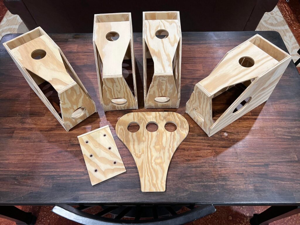
The four finished tail gunner seats, ready for for their metal bits.
The nail pattern on the far left seat is slightly different than that of the other three. Being for Lucky Thirteen, the nail spacing has to account for the older style hinge.
Photo taken 25 June 2024.
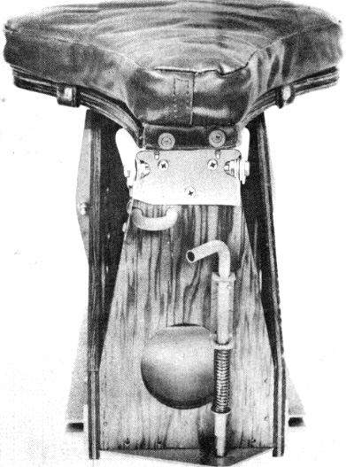
Manual illustration of the B-17’s tail gunner seat. The hinge on this seat is from the latter variant, introduced in December 1943.
The two rods for adjusting the seat are visible here.
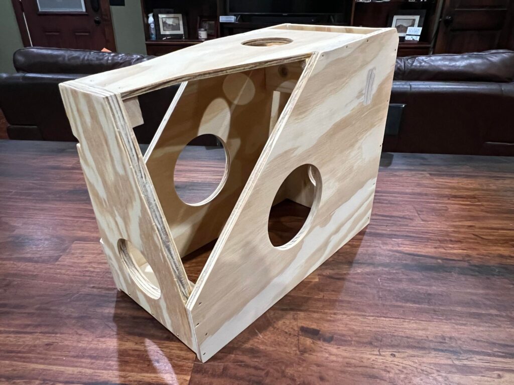
The tail gunner’s seat for Lucky Thirteen.
The forward ply is .5″ thick, the side plys .3125″ thick, and the top ply .1875″ thick. An unusual arrangement – but that is what the prints called for, and our research bore it out.
Photo taken 23 June 2024.
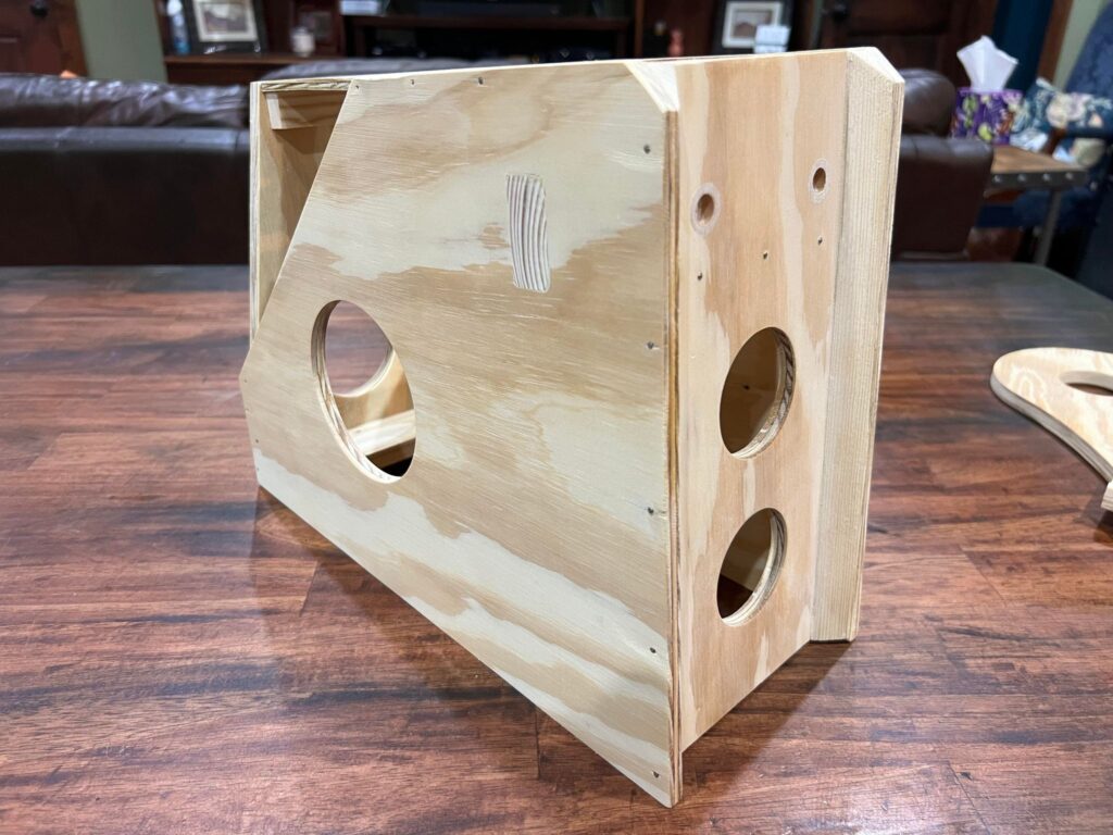
The tail gunner’s eat for Lucky Thirteen.
Most of the weight is supported by a solid piece of Spruce connecting either side of the box. Phenolic tubing, inlayed in the back, block, and adjuster panel pieces, strengthen the holes and help guide the adjustment rods. This is all accurate to the original design.
Photo taken 23 June 2024.
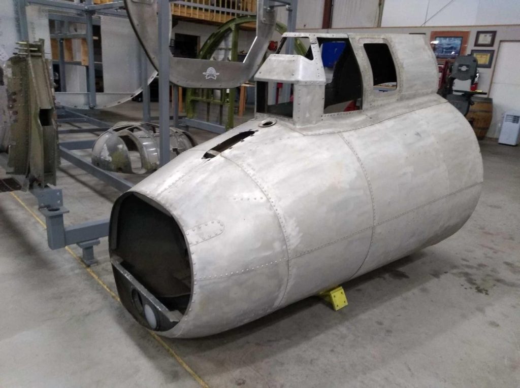
The tail gun assembly for Lucky Thirteen, taken from 42-30681, a veteran of the Aleutians Campaign that was lost just weeks after Lucky Thirteen.
Photo taken 30 May 2022.
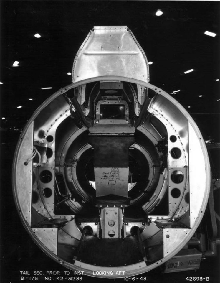
The tail gun position of 42-31283, a B-17F that never left the states. The ammo boxes have not been installed yet, though you can see where they would later be located. The gunner sits on the bicycle seat, his knees on the padding and his chest against the armor plate.
Photo taken 10 June 1943.
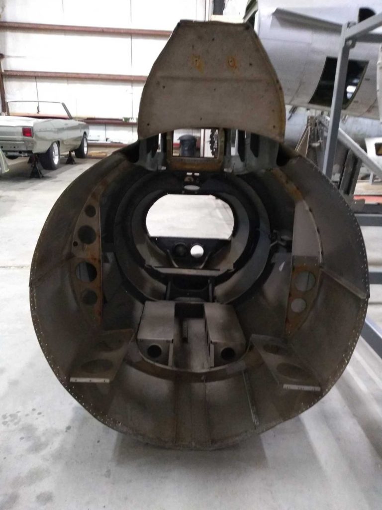
The interior of the tail gun assembly for Lucky Thirteen.
Previous owners had stripped many of the original bits, which will have to be replaced. Slowly but surely!
Photo taken 30 May 2022.

Manual illustration showing how the tail gunner sits in the stinger position.
The tail of an aircraft is often the most turbulent position, and the B-17’s stinger was heavily padded to compensate. Along with the seat, there kneepads, a chest pad, shoulder bumpers, and corner bumpers on each ammo box.
An additional canvas piece served as a hopper for dumping spent shells.
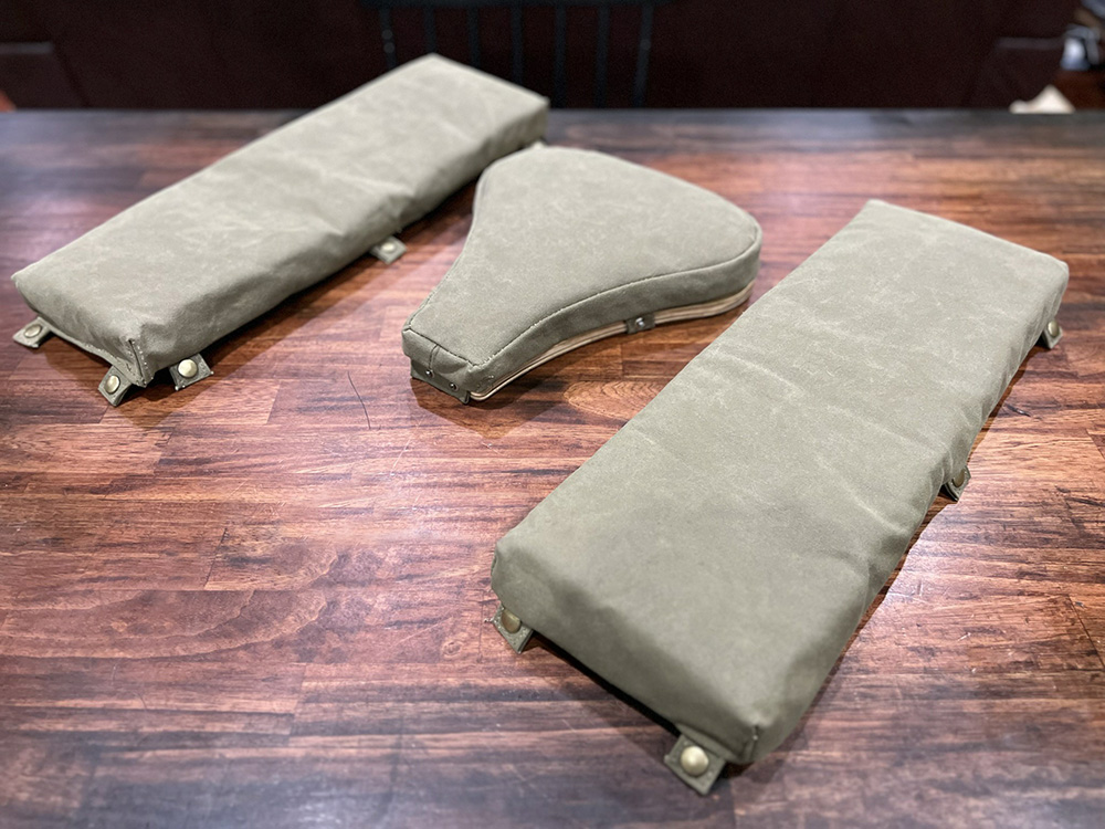
The seat and kneepads for the tail gunner position on Lucky Thirteen, kindly recreated for us by Mark Lewis of Beaver Mountain Leather Works in Canada.
These were made strictly following the original prints.
Photo taken 8 June 2023.
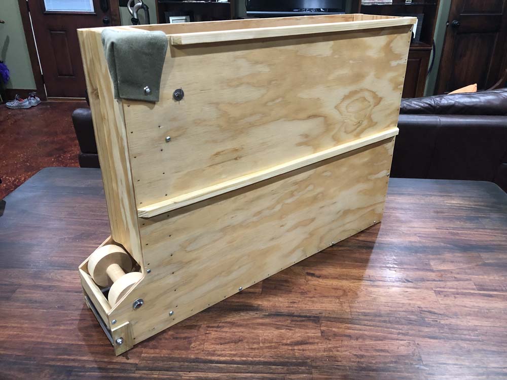
The right-hand tail gun ammo box for Lucky Thirteen on my dining table.
The ammo chutes which attach to the boxes will be problematic. While we have enough right-hand chutes to outfit Lucky Thirteen, we still do not have any left-hand chutes. In positions like this one, lengths of both right and left-hand chutes have to be mated so that the ammunition can reach the guns. If you can be of any help acquiring left-hand Hughes ammo chutes, please let us know!
Photo taken 16 October 2020.
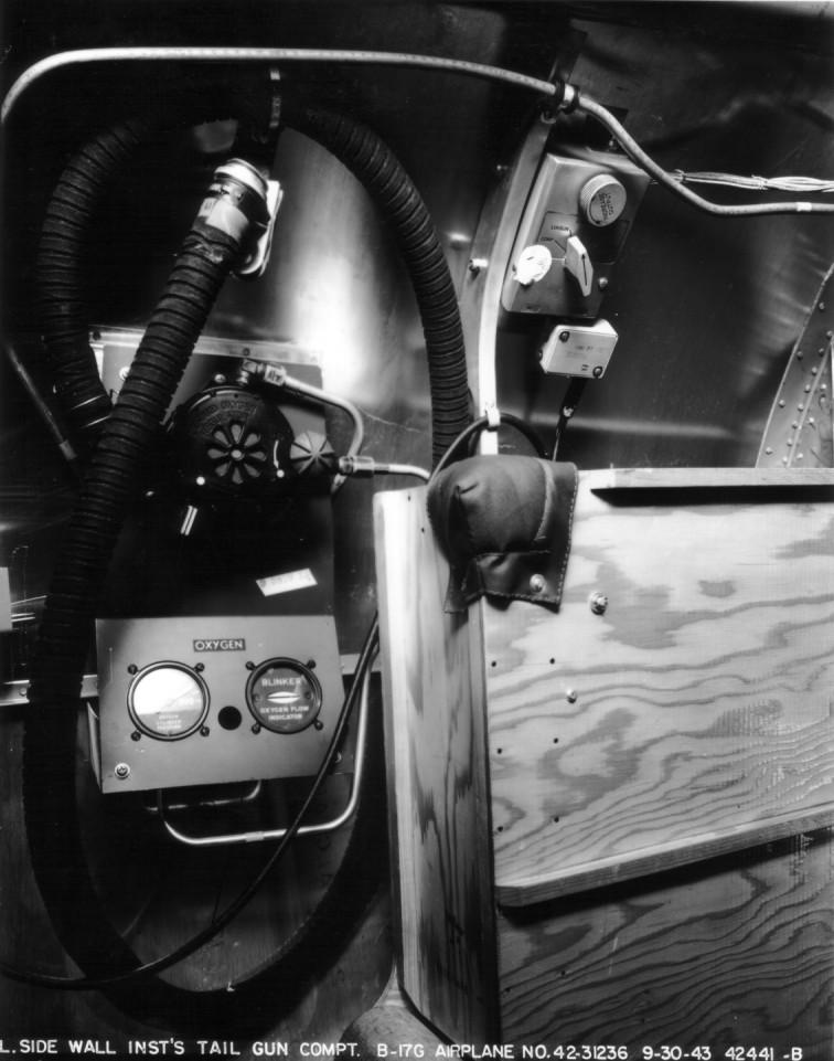
The right-hand ammo box in the tail of Arch Bishop (42-31236, 306BG). Due to the photo being black and white, it can be easy to mistake the corner pad for leather. It is not – it is canvas.
Note the small nails used to strengthen the wood panels, as period wood glue was notoriously poor.
Arch Bishop was lost on 11 January 1944 when another aircraft in her formation, Norah (42-31538, 306BG), lost control and collided with the bomber over Holland. There were no survivors.
Photo taken 30 September 1943
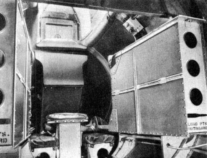
A manual illustration showing the tail gun position aboard an E or early-B-17F.
Note the metal seat assembly and ammo boxes, typical of these older aircraft.
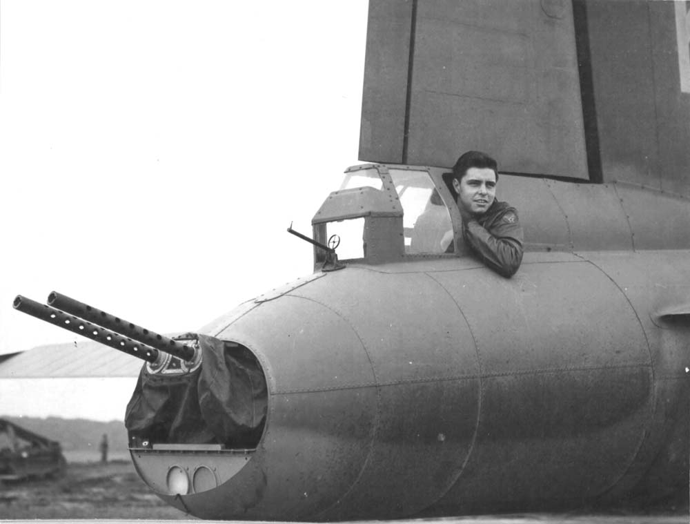
SSGT James F. Jones leans out the tail gun window of Gremlin Gus II (42-5904, 388BG). While the guns are still pointed upward for safety’s sake, the barrels have been removed for maintenance.
Gremlin Gus II crash-landed upon returning from a strike on 16 September 1943. The bomber was repaired for use in Project APHRODITE, being converted into a radio-controlled bomb. APHRODITE was cancelled before Gremlin Gus II could participate and she was scrapped at war’s end.
As longtime followers are likely aware, the recent work on the aft fuselage of the Lake Dyke B-17G (for the Liberty Foundation) has allowed us to shift gears on Lucky Thirteen toward her aft fuselage too. The goal here is to rebuild Stations 7 to 11. This entails the back wall of the waist (next to the main entry door) all the way to the tail stinger.
Since I do the carpentry work, this meant that I had to recreate the flooring in this section. The problem is the wood – it is not local. The B-17’s wooden components were almost all made of Douglas Fir plywood with Spruce hardwood stiffeners. While Spruce is easily obtained in the Carolinas, Douglas Fir is impossible to find. Specifically, Marine Grade AB Douglas Fir.
For a time, the closest supplier was Berlin Meyers in Charleston, though they no longer carry the material. This meant that I had to order the wood through the mail. I had done this before through Wood N Shop in Missouri and it had gone well. Unfortunately, when I ordered the wood for the tail flooring, there was a giant football patch in the middle of one piece – something I had specifically asked them to look out for and avoid.
If this wood had been in the waist compartment, it could be covered with the aircraft’s rubber matting. However, the flooring in the tail was bare, as there wasn’t enough room in this area to stand.
Rorry Pennington, a longtime supporter who I finally got to meet face-to-face with in Colorado, stepped forward. While he was not able to find an exact match, he was able to nevertheless locate Douglas Fir plywood, and he went out of his way to cut it down and ship the needed piece here. Thank you, Rorry, for going above and beyond!
This Douglas Fir issue is going to be a constant problem for us. For example, we are soon going to do the bomber’s tail gunner seat. We plan on doing multiples of this, including one for our friend Dave at the B-17 Cockpit Project. So, if anyone has access to Douglas Fir Marine Grade AB plywood, in sizes 3/16, 5/16, and 1/2, and would be interested in helping, please let us know! These can be shipped to us no smaller than in 14 inch squares.
Speaking of above and beyond, another contribution comes to us via our good friend Max Pearsall in Pennsylvania. This regards the Consolidated LB.30 (B-24) we are rebuilding with Project Warbird –
One of the pieces I was to pick up in Pennsylvania was the B-24’s APU. The APU, or Auxiliary Power Unit, was a small gasoline-driven generator used by ground crews to provide electrical power for the bomber without having to start its main engines. Eric had acquired an example and Max offered to hold it until I could come up and retrieve it. Max’s dad held it since Max was on active duty (Max is currently serving in the US Air Force) and, much to our surprise, we learned that Max had gone so far as to purchase the APU himself as a contribution to the project.
Longtime followers are likely aware that Max has contributed parts to the B-17 in the past, so it is an honor to have his support on the B-24 as well.
Another recent bit of good news comes from our good friends at the Liberty Foundation. They have kindly loaned us components to Type E-11 and Type E-13 gun cradles so that we can CAD model them.
Lucky Thirteen carried five Type E-11 gun cradles, being used in the nose, cheek, and tail gun positions. Unlike the lightweight E-12 used in the waist, which absorbed recoil using a spring-mechanism, the E-11 was a heavy, cast assembly which absorbed recoil using a pair of pistons. We had hoped that our involvement with the “Masters of the Air” series might give us a shot at the E-11s recreated for the series, but this proved to not be the case. Since the collector’s market makes E-11s far more costly than we could ever realistically manage, we have decided to look into creating new ones. CAD modeling them will be the first step.
A recent donation we would like to highlight comes from David Simmons of Shortsville, New York, who was awesome enough to donate a NOS bailout bell to the project. Not only does it come with its original packaging, but David also did a live test of the bell before sending it down.
To Rorry Pennington, David Simmons, the Liberty Foundation, and Max Pearsall and family – our sincere thank you for your support.
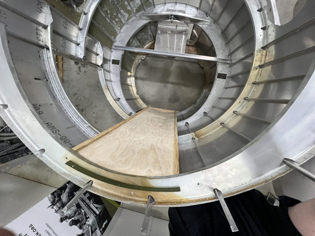
The newly completed floor between Stations 9 through 11 is temporarily laid in place. Note the tail gunner’s escape hatch on the left.
Photo taken 17 May 2024.
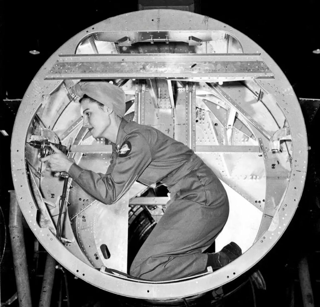
A Boeing employee poses beside Station 11 in a B-17F. This is the aftmost fuselage component prior to the tail stinger assembly.
The wooden floor can be seem just below her knees.
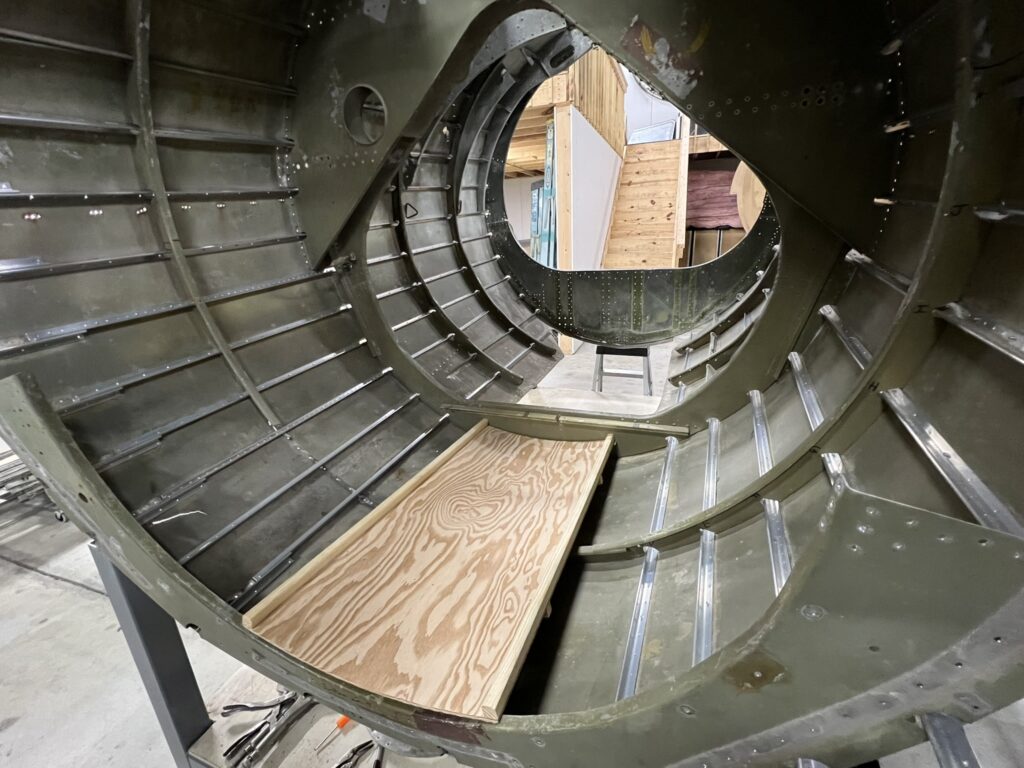
The newly completed floor between Stations 8 and 9 is temporarily laid in place. On older B-17s like Lucky Thirteen, a wooden door separated the tail gunner from the tail wheel.
Note the silver stringers. These are part of the rebuilding process, taking out old, corroded pieces and using them as patterns to make new ones. The green in here was sprayed by a previous owner is not original.
Photo taken 17 May 2024.
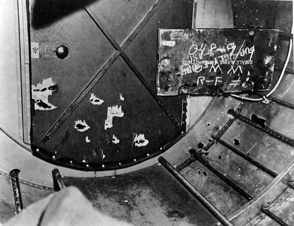
A wartime picture of the wooden door separating the tail gunner from the tail wheel. Note the wooden floor below.
While the blueprints say to leave the wood unpainted, the builders of this aircraft have elected to paint them.
The wooden square on the far right, being used as a placard, is in reality the top to an ammunition crate.
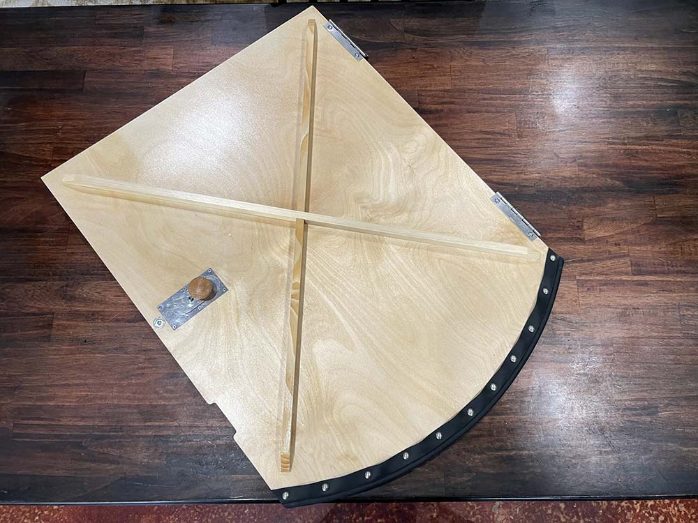
The recreated tail gunner’s crawlway door for Lucky Thirteen.
Photo taken 20 February 2023.
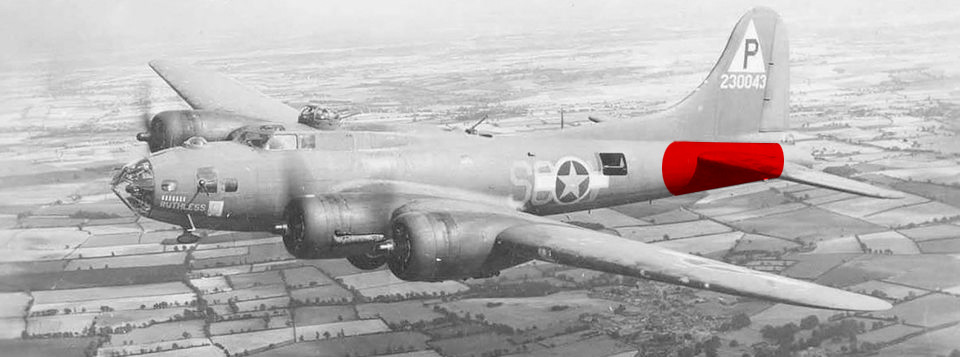
Ruthless (42-30043, 384BG) is highlighted to show the fuselage portion currently being rebuilt for Lucky Thirteen.
Ruthless served in the same unit as Lucky Thirteen and was lost on 4 October 1943, ditching in the North Sea on the return flight home. All ten of her crew survived, being picked up by the trawler Lord Keith.
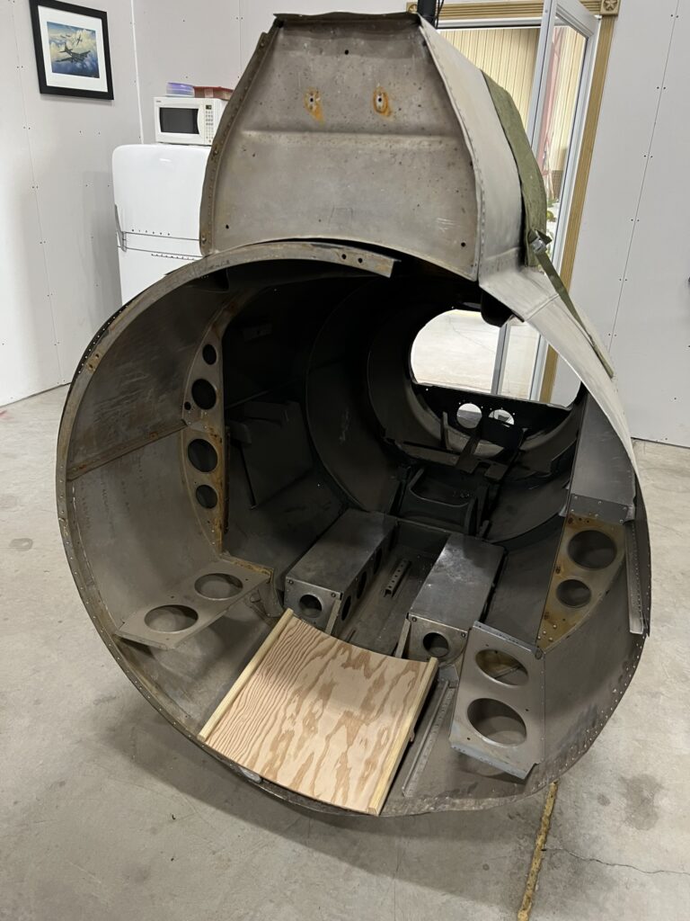
The small piece of flooring for the stinger compartment is temporarily laid in place.
Photo taken 17 May 2024.

Factory photo of the stinger position with the floor visible.
Note the armor plating the gunner lays his chest against. This is 5/16 RHA steel. The armor in the tail was a sixteenth inch thicker than the armor elsewhere in the aircraft. If anyone can help us acquire RHA (Rolled Homogenous Armor) please let us know!
Photo taken 6 October 1943.
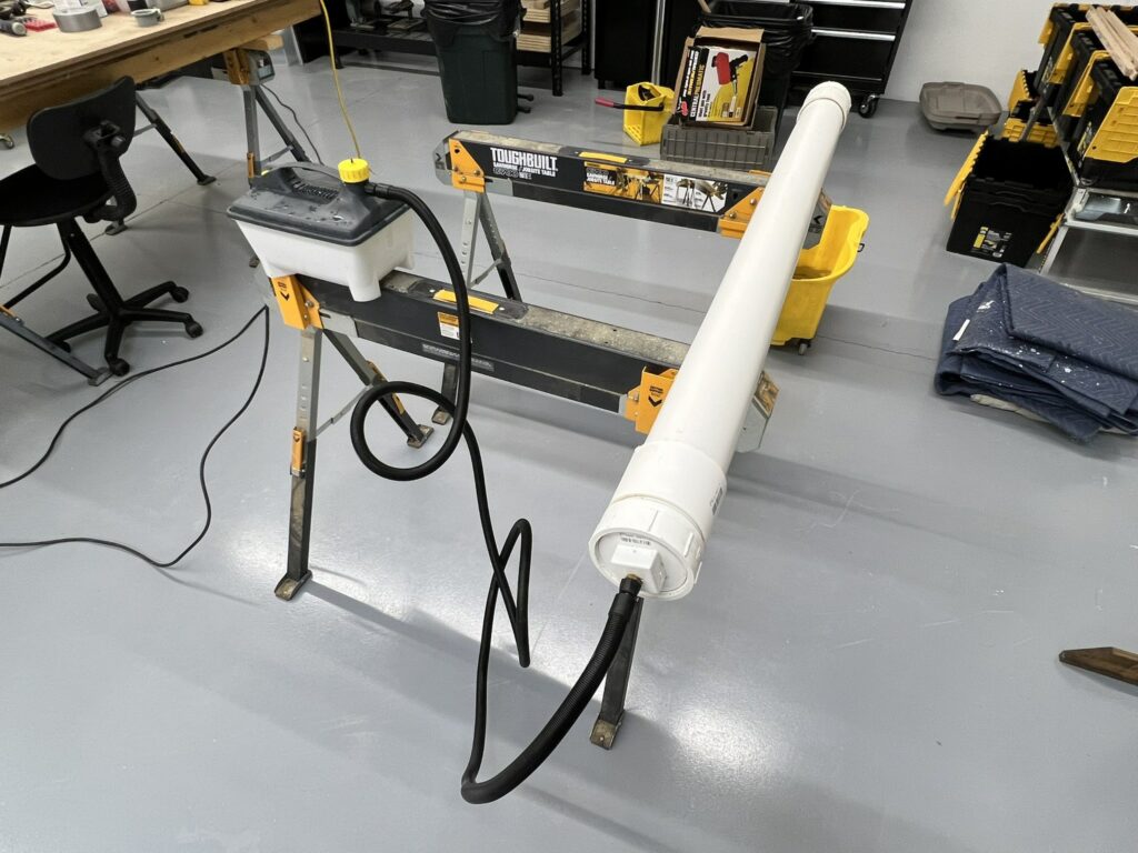
Great care was required in recreating the floor bits as they hugged the curvature of the fuselage.
The stiffeners under these floors were made according to the original methods, layering plys together. The first step was to steam said plys.
Photo taken 25 April 2024.
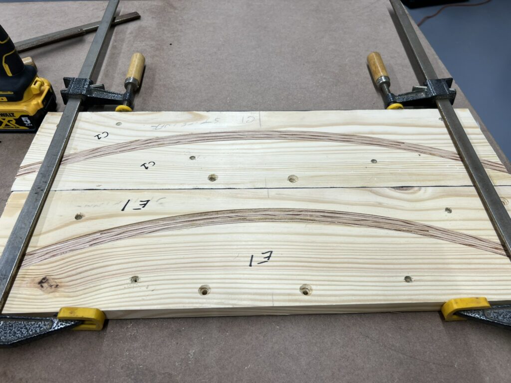
The steam plys were glued together and placed into jigs, which had been CNC’d to match the curvature of each point in the fuselage where the stiffeners would eventually go.
Photo taken 26 April 2024.
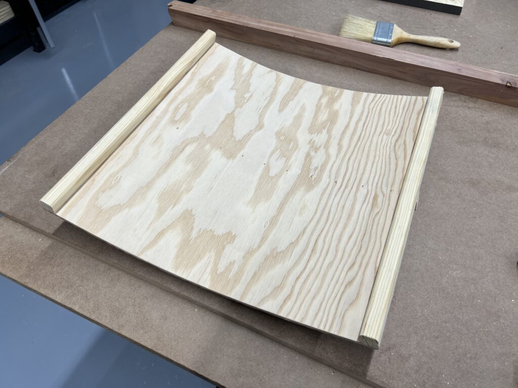
The finished tail flooring for the stinger section. The upper section is seen here. Everything you see here is strictly to blueprint spec, even the spacing of the brad nails (used to strengthen wartime glue, which was weaker than modern glues).
Photo taken 28 April 2024.
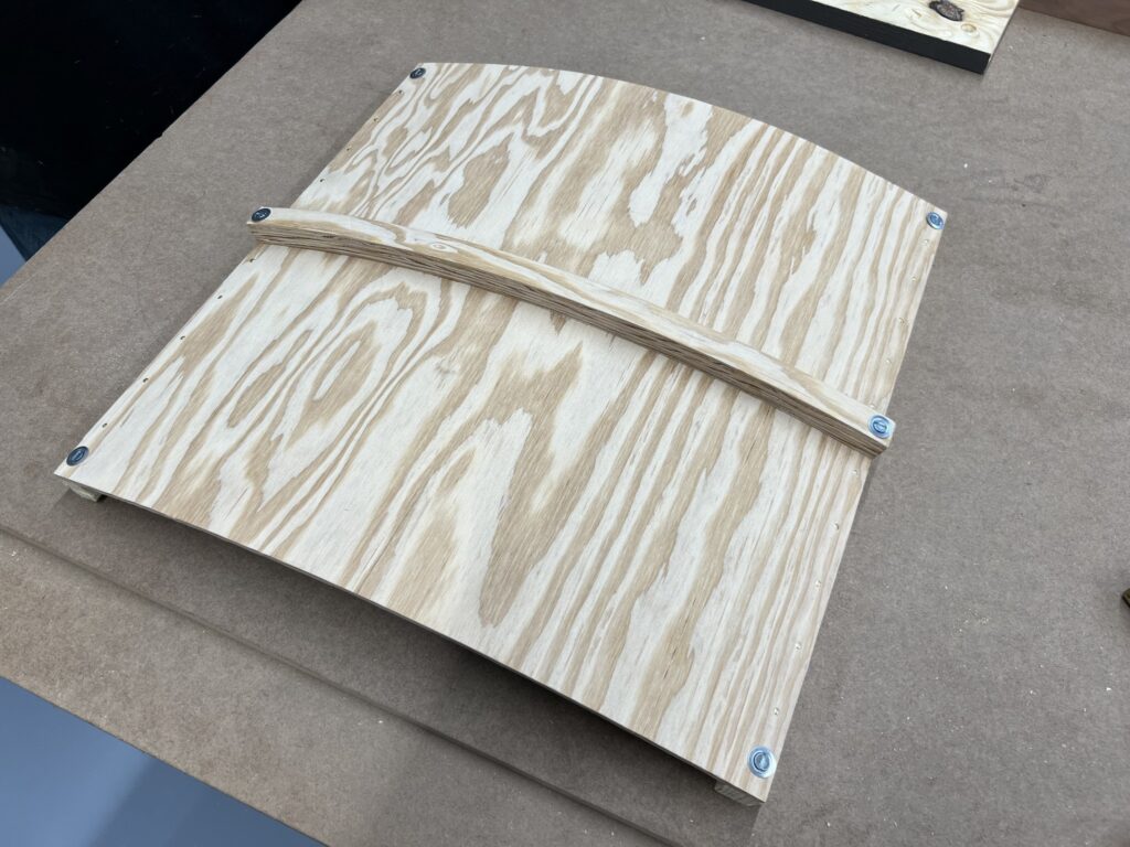
The finished tail flooring for the stinger section. The lower section is seen here. A steamed stiffener is visible.
Photo taken 28 April 2024.
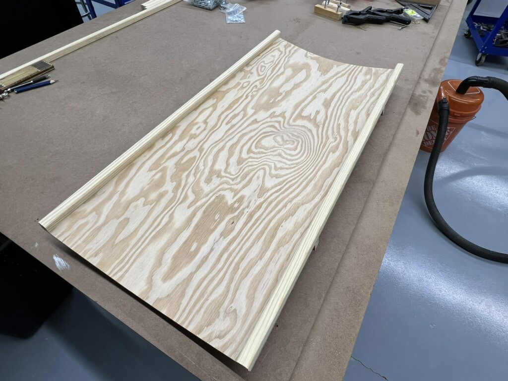
The finished tail flooring for Stations 8 through 9. The upper section is seen here. Everything you see here is strictly to blueprint spec, even the spacing of the brad nails (used to strengthen wartime glue, which was weaker than modern glues).
Photo taken 30 April 2024.
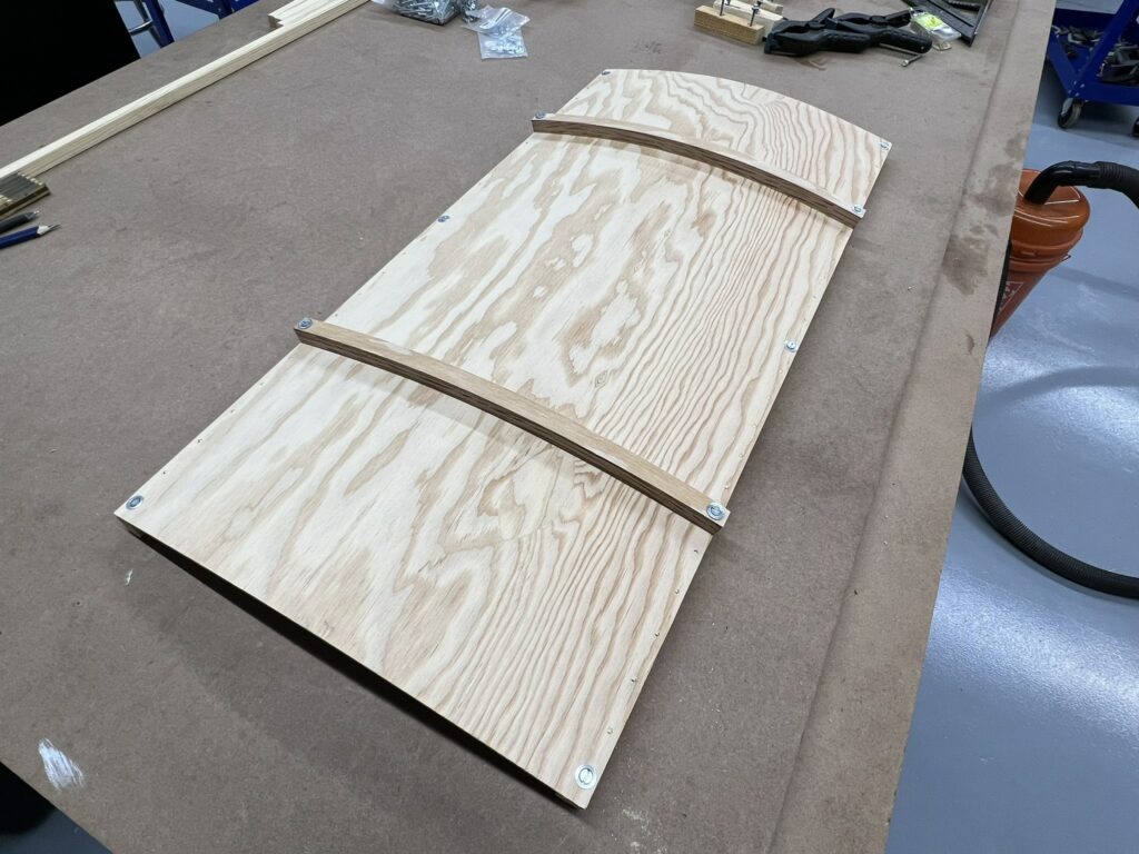
The finished tail flooring for Stations 8 through 9.
The lower section is seen here. A steamed stiffener is visible.
Photo taken 30 April 2024.
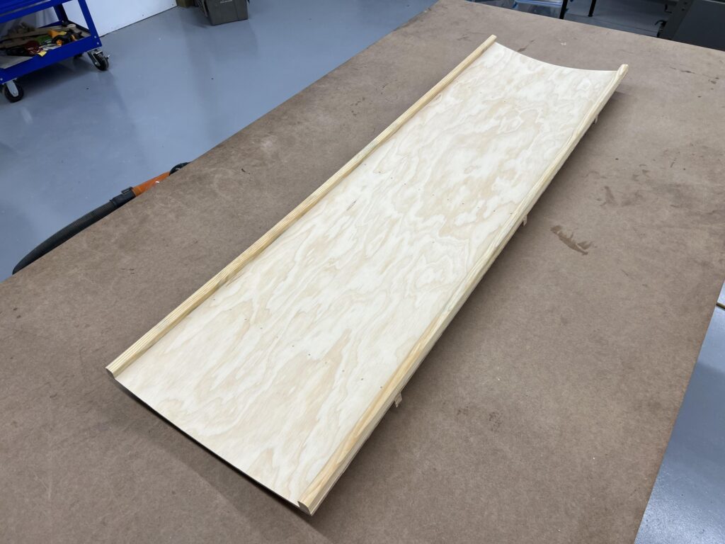
The finished tail flooring for Stations 9 through 11. The upper section is seen here. This is the Douglas Fir purchased and mailed to us by Rorry in Colorado.
Photo taken 6 May 2024.
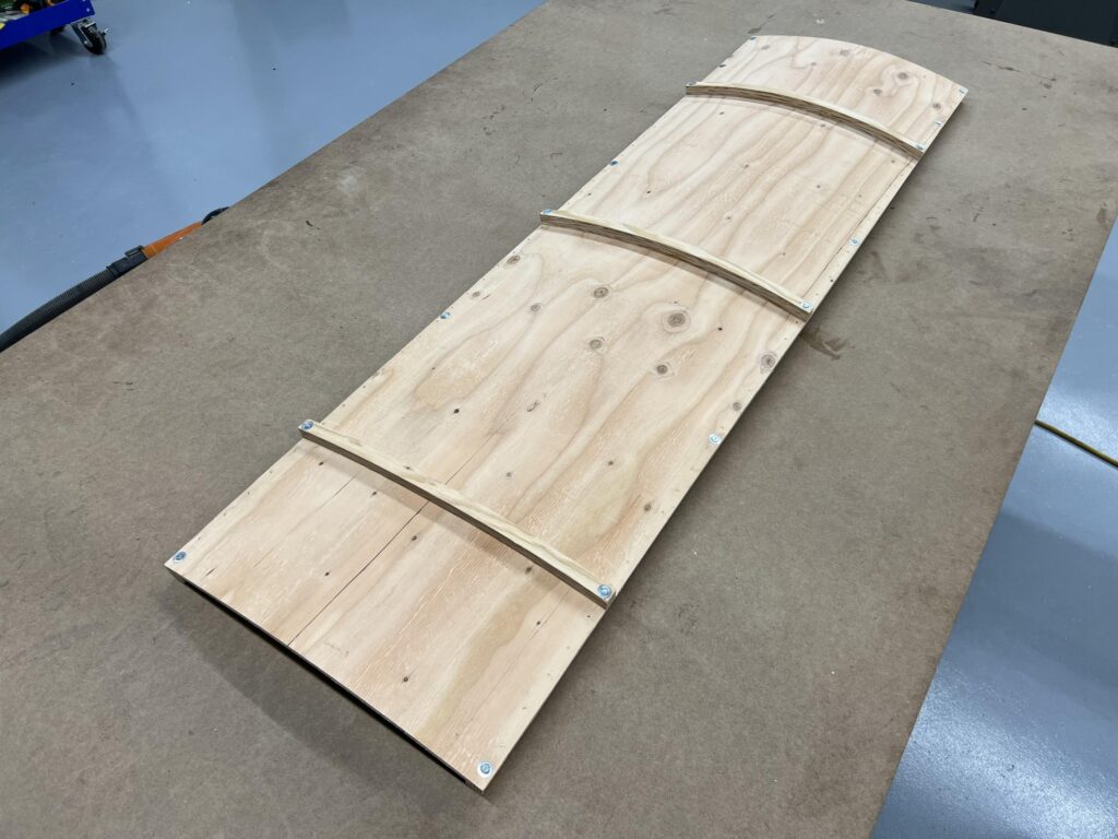
The finished tail flooring for Stations 9 through 11. The lower section is seen here. This is the Douglas Fir purchased and mailed to us by Rorry in Colorado.
You might notice the grain pattern is not as pristine as the other two floors. That is because the others were grade AB and this is grade AC. However, for all pieces, the grade A sides will be facing upwards – so all is good.
Photo taken 6 May 2024.
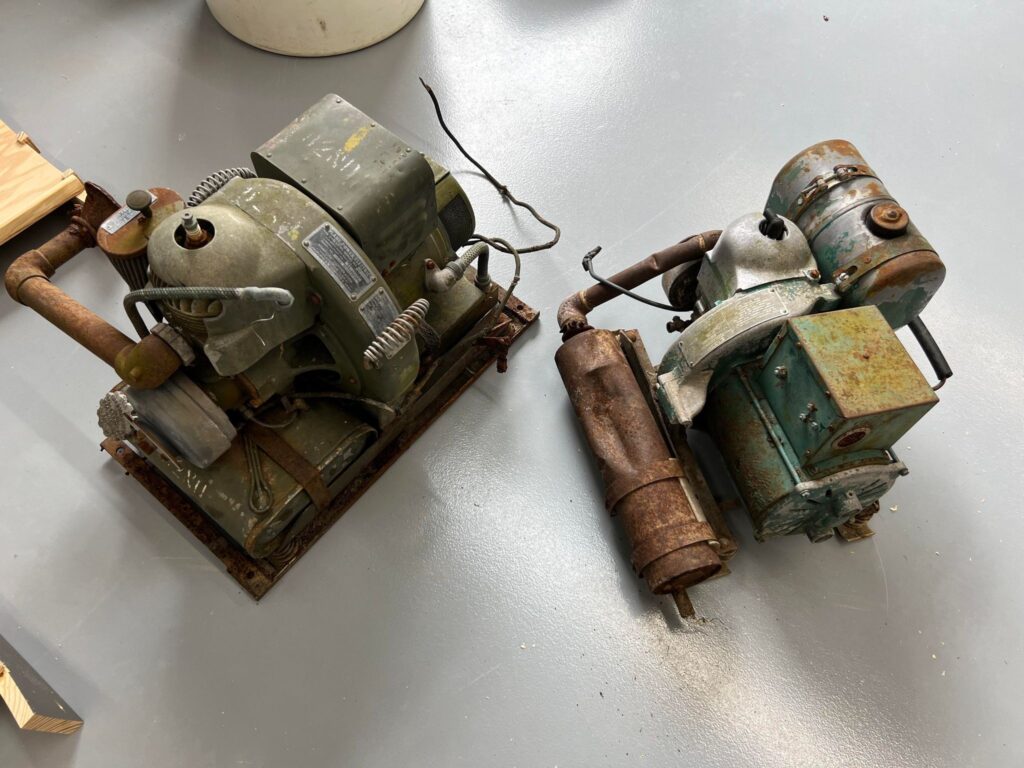
Max’s newly donated APU for Maid of Athens.
The piece on the right was included in the purchase for use of spare parts.
Photo taken 13 May 2024.
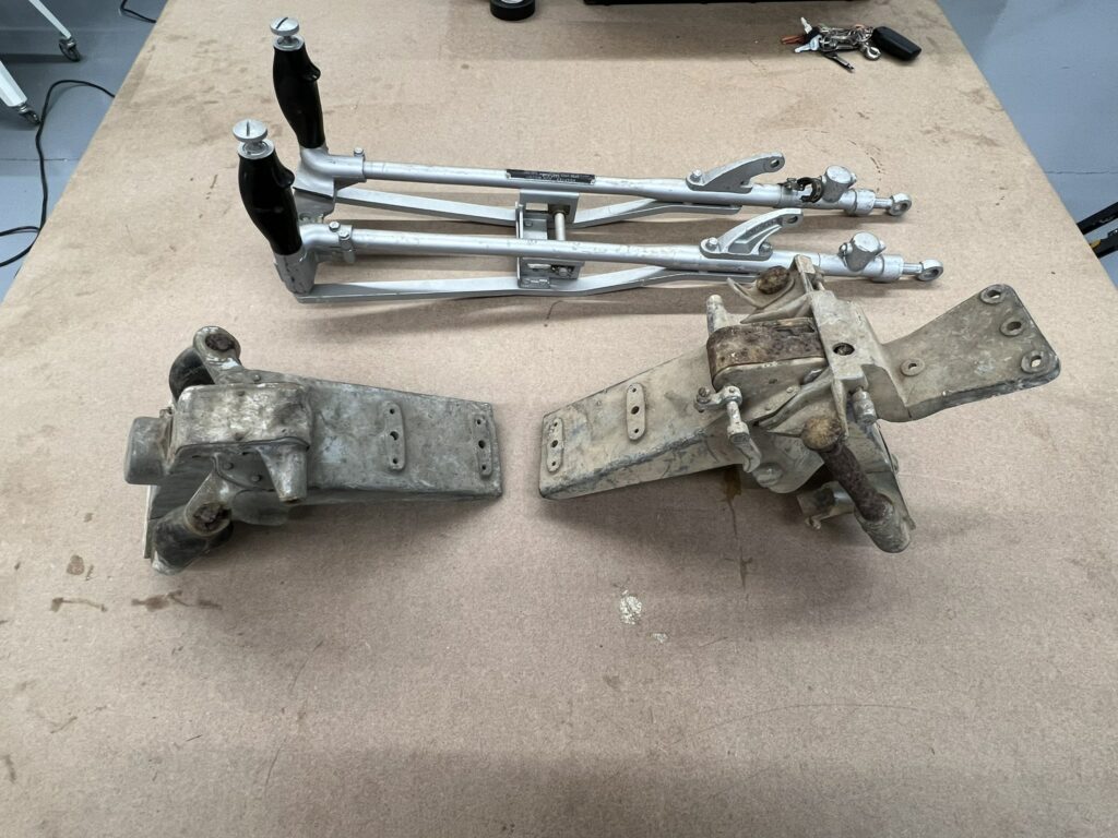
The E-11 and E-13 Gun Cradle components loaned to us by the Liberty Foundation. The E-11 piece is on the left, while the E-13 pieces are above and one the right.
The E-13 was a late war design based on the E-11 but slightly altered to support a K-13 computing gunsight.
Photo taken 22 April 2024.
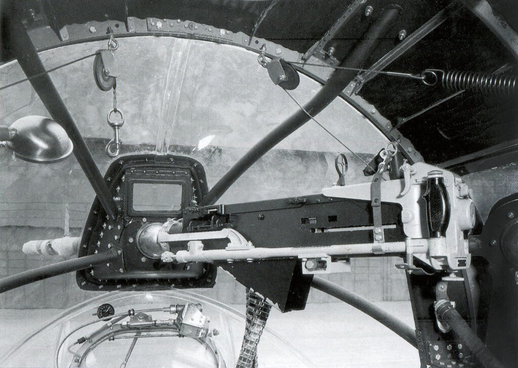
Factory photo of a Type E-11 gun cradle affixed in the nose position of a Boeing B-17F. A deflector has been added under the gun so the ejected shells will fall away from the nose.
A Type C-19 Adapter connects the cradle to a Type K-4 Ball Mount affixed to the Cheyenne nose assembly. The gunsight is a Type B-13 ring and Type A-11 Bead.
All of these will be needed for Lucky Thirteen. Thankfully, Project Warbird has acquired a Type K-4 Ball (and has asked that we help locate for the LB.30 a .30 cal ball socket) and we have acquired the triangular Cheyenne assembly (quite possibly the last one in existence). If anyone can help with the other components, please let us know!
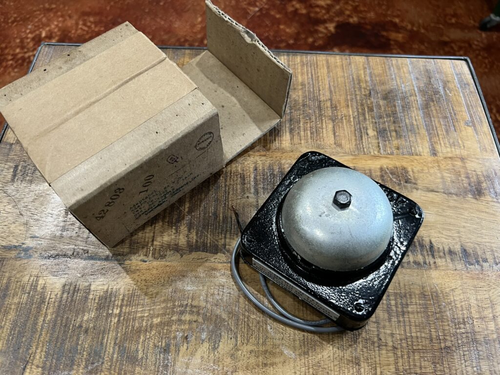
David’s newly donated NOS bailout bell.
The bell was manufactured by Edwards and Company of Norwalk, Connecticut. Founded in 1873, Edwards & Co. were early pioneers in doorbells and burglar alarms. Today they still exist as Edwards Signaling and Security, though they are now a subsidiary of General Electric.
Photo taken 17 May 2024.
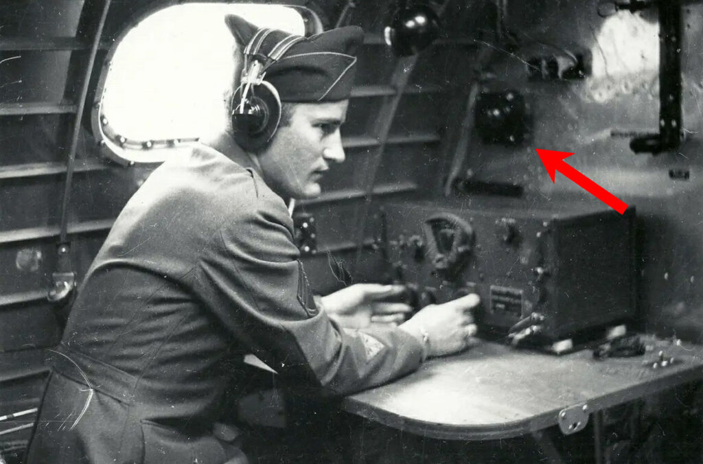
TSGT Normand J. Vicknair of the 384BG at the radio operator’s position aboard a B-17G. The radio operator’s bailout bell has been highlighted.
There were multiple bailout bells onboard the aircraft, being controlled by the pilot. The idea was to indicate an emergency in case someone could not hear the intercom call for bailout.
The 384BG was the same unit with which Lucky Thirteen served.
As longtime supporters may be aware, Hangar Thirteen has no wealthy benefactor. So far, we do not bring in enough donations to fund the rebuild of Boeing B-17F Lucky Thirteen independently. So, we supplement donations by rebuilding components for other B-17 projects. While this approach slows work on Lucky Thirteen, it gives us access to patterns and trades which we could otherwise never afford.
Today we are sharing pics of our work for Lacey Lady of the B-17 Alliance Foundation in Salem, Oregon.
Lacey Lady is famous for her long tenure as décor above a gas station, serving as a canopy for some 67 incredible years. The aircraft is a true time capsule, her interior being virtually untouched. A while back, Ray rebuilt the outer compression struts for this aircraft. Now, he has done the same for the bomber’s bomb bay catwalk.
It should be noted that the B-17’s bomb bay was built around the aircraft’s carry-thru spars. These carry-thrus comprised the lower halves of Stations 4 and 5, the outer compression struts and catwalk serving to create a sort of box frame. In the end, this frame forms the backbone of the B-17, supporting the weight for the rest of the aircraft.
We are honored to have played a role in the restoration of this historic bomber and look forward to seeing her returned to her former glory once more.
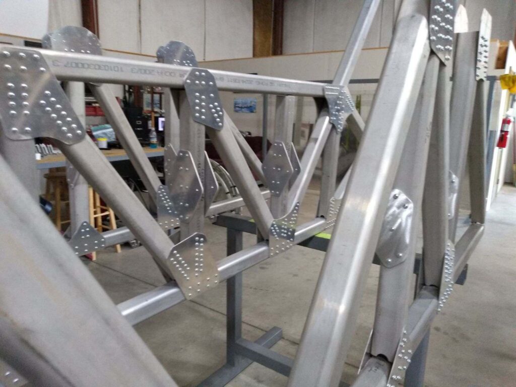
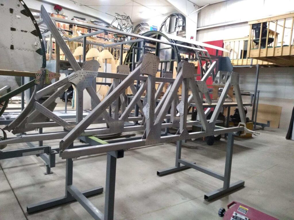
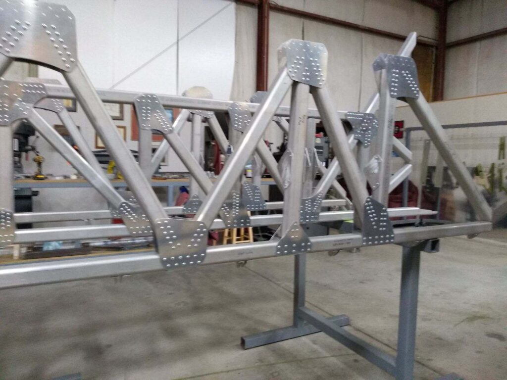
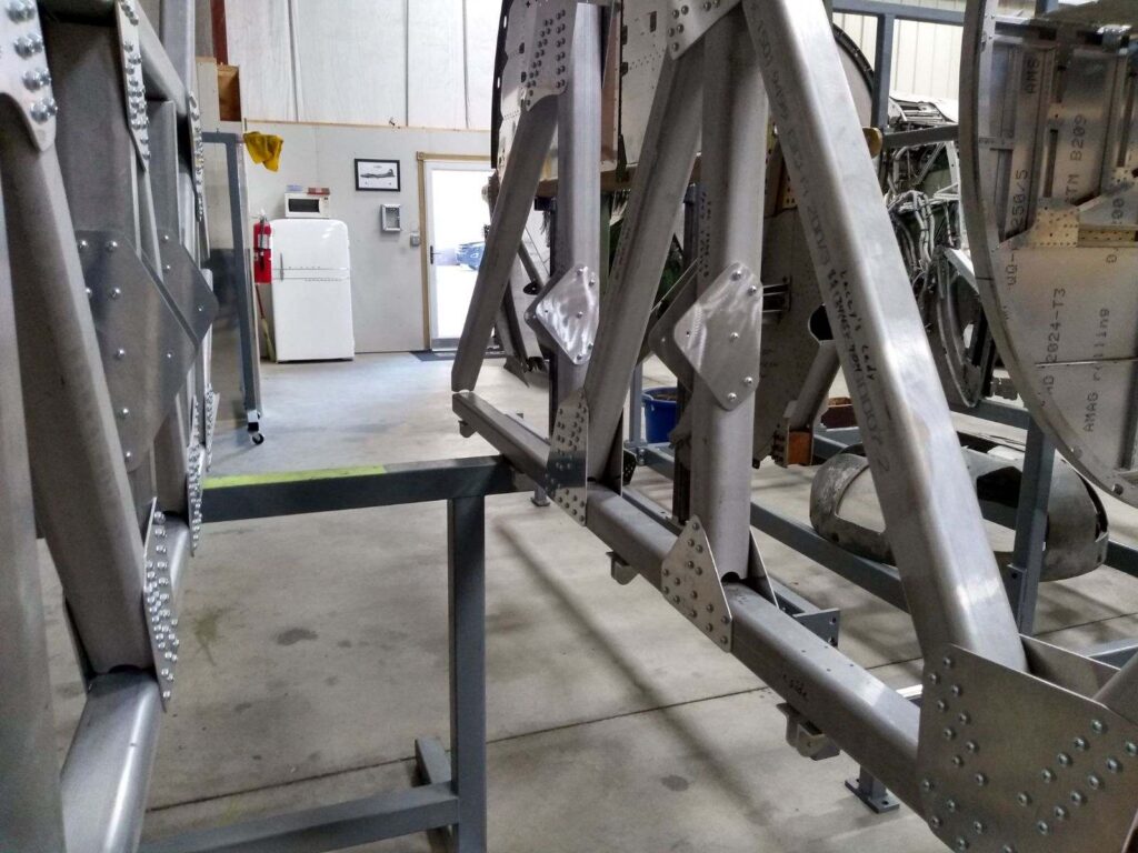
The outer compression struts and bomb bay catwalk for Lacey Lady (44-85790).
Everything is temporarily held together with screws to make finishing and transportation easier.
Photo taken 20 May 2024.
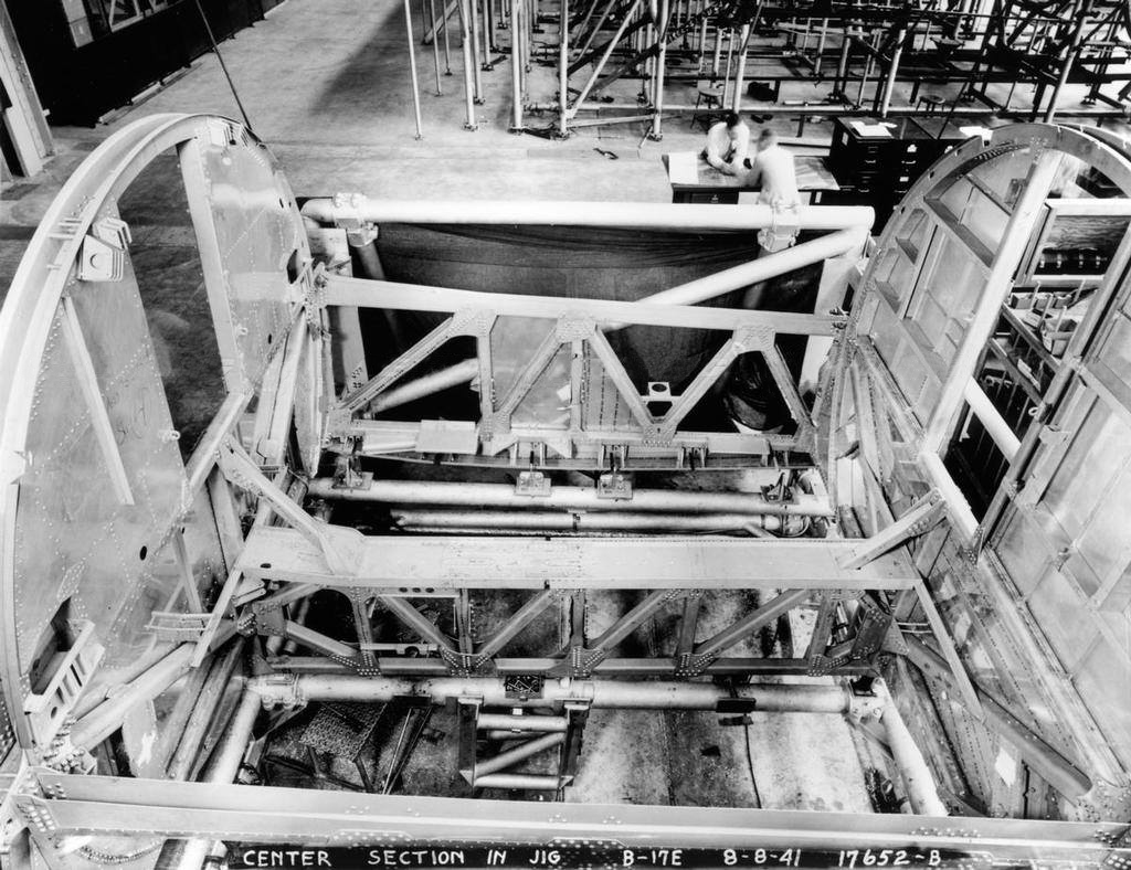
Boeing factory photo of a B-17E bomb bay section, the outer compression struts and bomb bay catwalk affixed to the carry-thrus under Stations 4 (left) and 5 (right).
Photo taken 8 August 1941.
I wanted to start by showcasing some recent work on the ball turret. The turret’s fuse box has been cleaned and recoated to bring it back to its 1943 appearance. The Type A-2 Ball Turret was electrically powered, operating on 28V 100 amp power supply, brought into the ball by a canvas covered conduit. The fuse box contained connectors for the turret’s motor, hand control, fire cut-off, heated suit, talk circuit, and gunsight. On older turrets like ours, the firing solenoids and trouble light were also hooked through connectors, though later turrets hard wired these pieces.
We are in need of a 28V 100 amp power supply for turret motor checks and demonstrations. DB Assembly and Bycan both make 28V 100 amp power supplies but the prices for these units can be rather extreme. If you can help with this need, please let us know!
Speaking of the ball turret, we were recently donated a transmission by Matthew Moab of Moab, Utah. The timing was perfect as I am soon to start taking apart our transmissions to begin restoration, the goal being to pull from the transmission wrecks in order to have four perfect units for the ball and upper turrets. What makes Matthew’s transmission special is that it still has its mount assembly for attaching the transmission to the turret wall, as well as its hydraulic drip line. Thanks Matthew!
Apart from the hydraulic drip pan, missing azimuth control rod, broken elevation control rod, and broken elevation control rod connector on the hand control, we now have all the major components necessary to restore the ball turret’s motor assembly. The last major component, the hydraulic reservoir tank, has recently been acquired. While a finished turret may take years due to the extreme cost of body components, we can at least restore its motor assembly so that, when the day comes that we have all the body components, we can drop the motor in and be ready to go!
Another recent acquisition came from Walter Futrell of Colonial Heights, Virginia, who was recommended to us by our friend Bossman Wylie! Walter had located a Type A-2 carbon tet extinguisher, complete with its original bracket, and offered it to the project. This unit was in fantastic shape and cleaned up beautifully. Along with the older unit we recently restored, and the unit being restored by volunteer Chris Ely of Branson, Missouri, we now have a complete set of carbon tets for Lucky Thirteen.
The only extinguisher still left for the aircraft is the last Type A-17 CO2 extinguisher. Some of you might recall that the bomber’s third A-17 was damaged. If said repair can be safely accomplished, then all of the aircraft’s extinguishers will be restored!
In other news, the three spare lamps boxes are now finished, with their spring latches and decals now installed. These boxes were 3D modeled by volunteer Kevin Davenport of Jacksonville, Florida, the springs fabricated by volunteer Bob Hachmann of Peosta, Iowa, and the boxes molded by Schmidt Proto of Minneapolis, Minnesota. Kevin has recently announced that, because of some recent changes in his work, that he will no longer be able to volunteer his CAD skills. Gonna miss you buddy!
Speaking of Bob, one of his current projects is fabricating the housing for the bomber’s instrument panel. Unlike B-17Gs, which had wooden panel housings, older B-17s had aluminum panel housings. In anticipation of Bob’s work, the final phenolic face places for the instrument panel have been cut. As some of scale modelers know, the top of the B-17’s nose had a unique curve, so these panels were sent to Bob so we could work together to get said curve exactly right. When the housing is finished, we will paint up the plates and get the markings applied. We cannot wait to see the finished project – it will be an accomplishment years in the making!
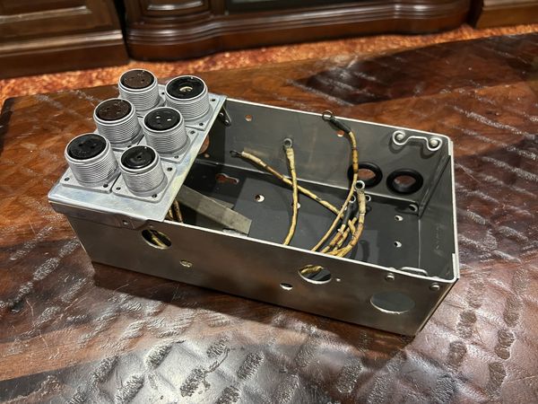
The fuse box for the ball turret on Lucky Thirteen is cleaned and recoated to protect against corrosion. The plugs for the main power, trouble light, and firing solenoid are missing and will need to be replaced. Likewise, new rubber ‘conduits’ will need to be created to run the power from these various plugs.
Two companies manufactured the Type A-2 ball turret for Sperry Gyroscope: Briggs Manufacturing of Detroit, Michigan and Emerson Electric of St. Louis, Missouri. On Briggs-built turrets, the fuse box was unpainted, while on Emerson-built turrets the box was green. The vast majority of wartime ball turrets – including the one installed on Lucky Thirteen – were built by Briggs.
Photo taken 29 April 2024.
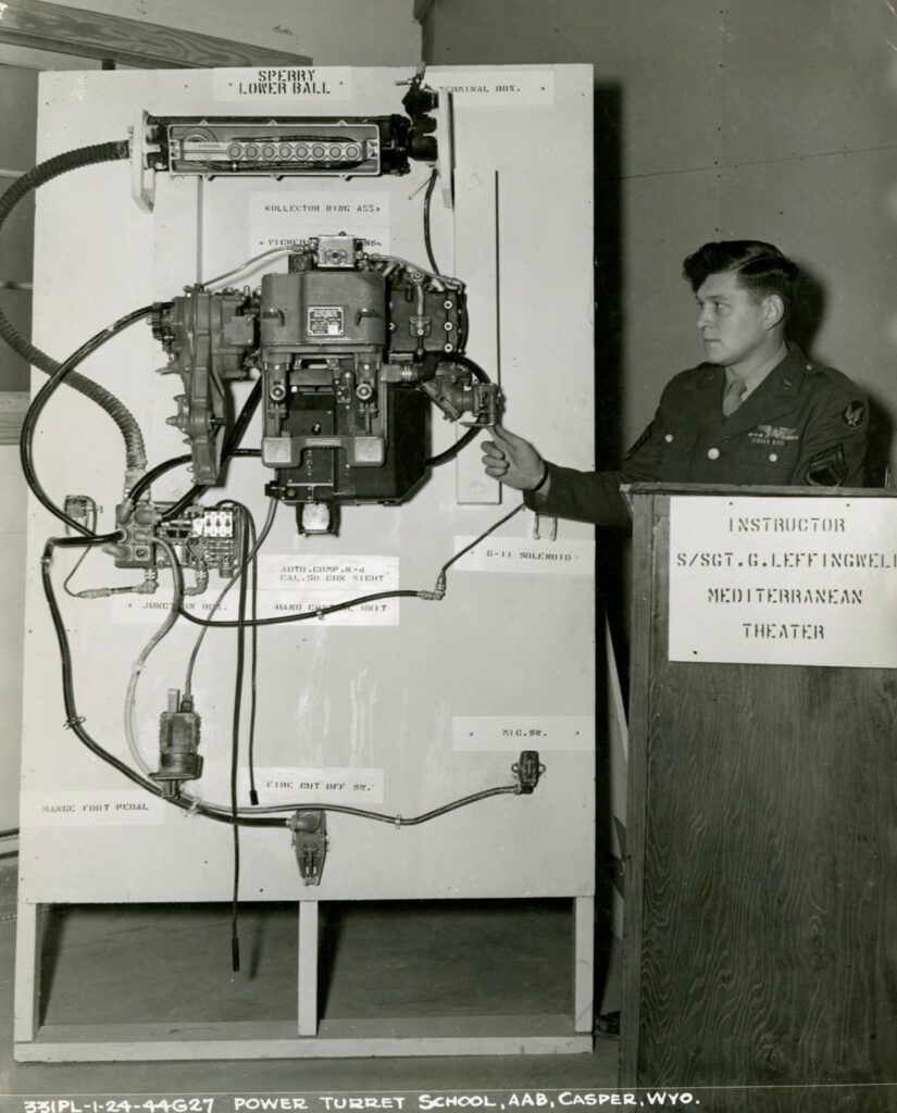
SSGT George R. Leffingwell of Darlington, Wisconsin gives a lecture on the internal components of the Type A-2 Ball Turret. A veteran of the 99BG (15AF), Leffingwell completed his combat tour and returned home as a gunnery instructor.
The components shown here are identical to those that were installed on Lucky Thirteen and we would love to recreate the display shown here.
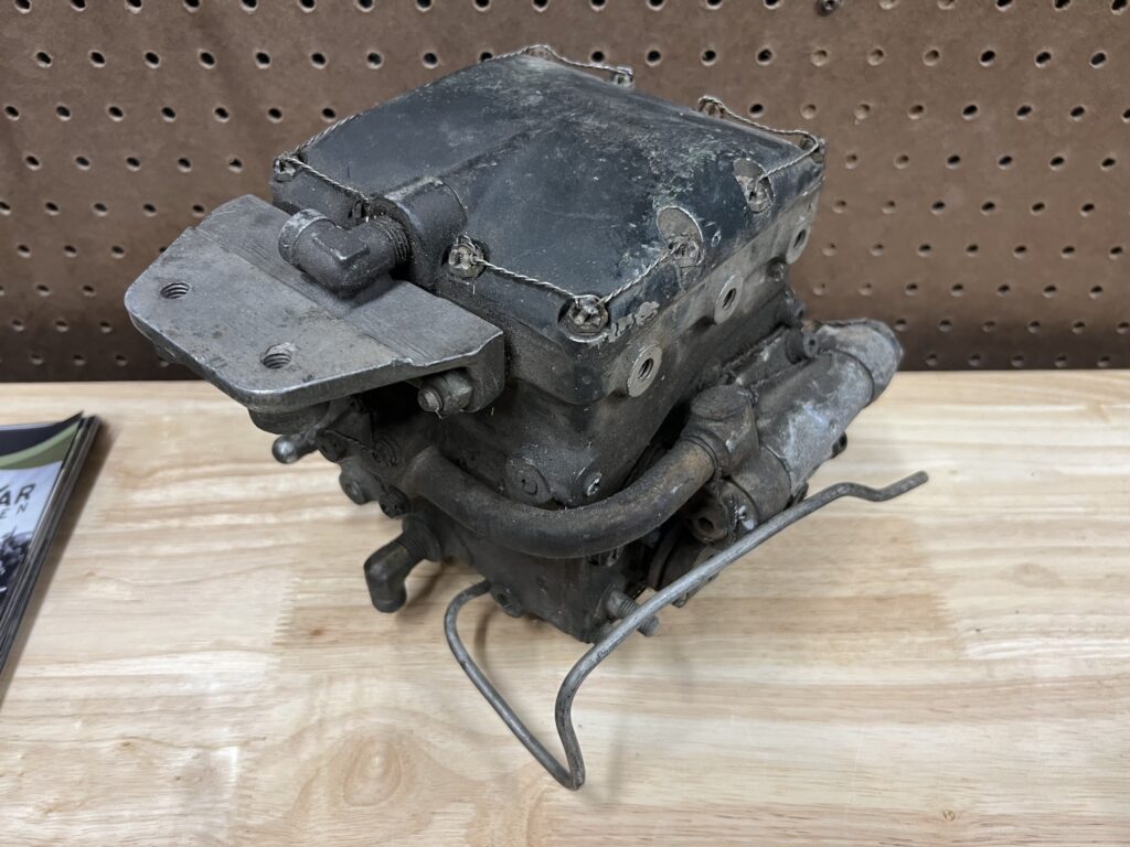
Matthew’s newly arrived turret transmission. The mount which indicates that it came from a ball turret is visible on the left. The gray paint on the mount shows that said turret was a Briggs.
The double power unit, consisting of the electric motor and hydraulic transmissions on either side, were manufactured by third parties. As such, the double power units were always green.
Photo taken 29 April 2024.
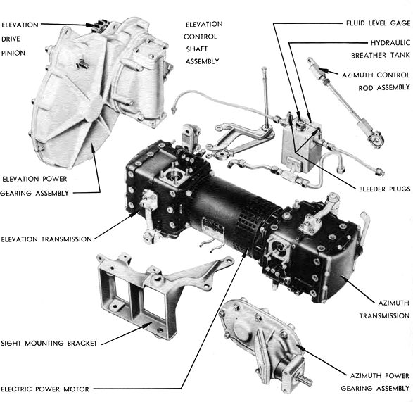
Manual illustration of the motor assembly to the Sperry ball turret.
We have every component shown here except for the azimuth control rod. Our elevation control rod is broken and requires repair.
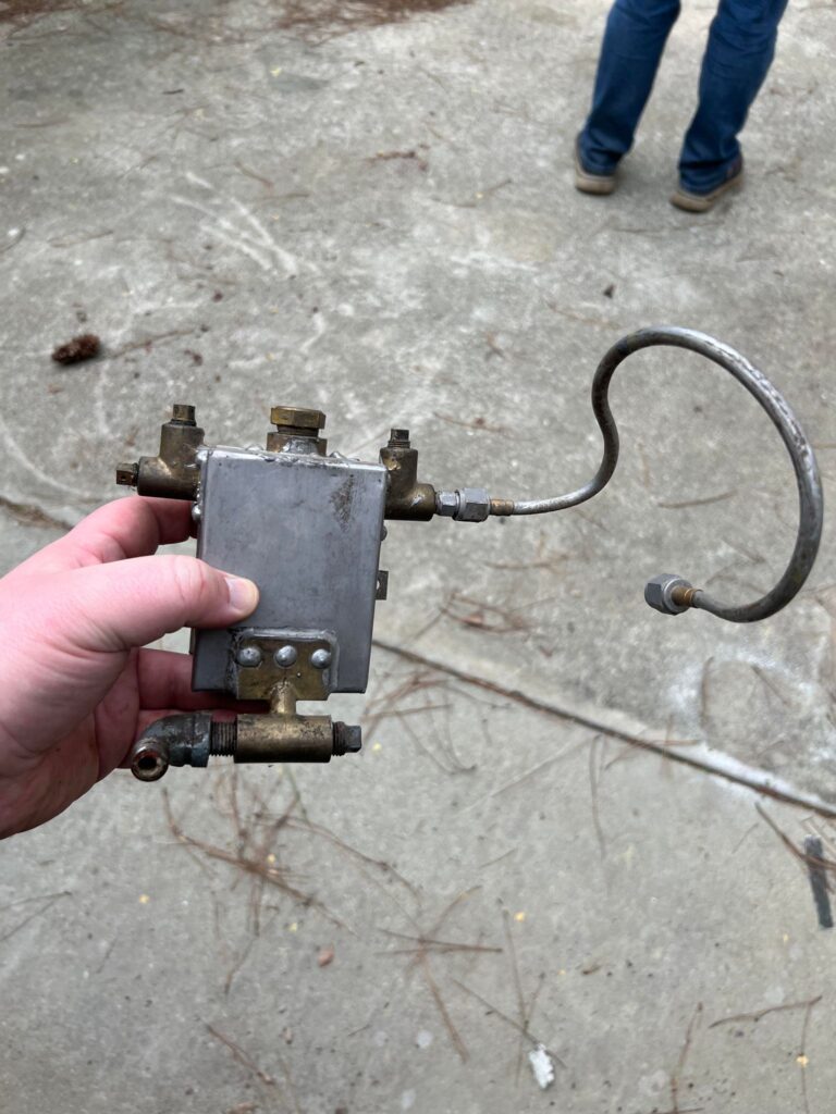
The newly acquired hydraulic reservoir for the Type A-2 ball turret.
The craftsmanship behind this tank’s construction is surprisingly rough.
Photo taken 2024-3-22.
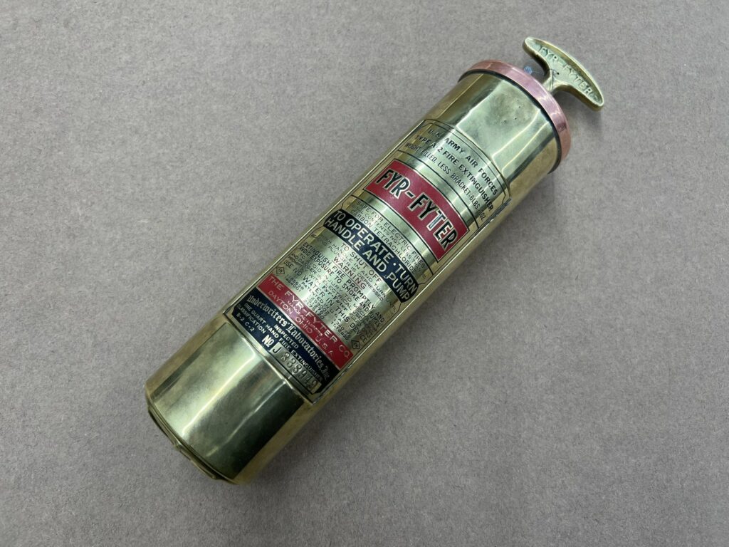
The newly arrived Type A-2 carbon tet extinguisher is fully restored.
The only imperfection is a small dent in the top, caused by the buckle which holds the unit in its bracket. A lovely detail.
Photo taken 2024-4-8.
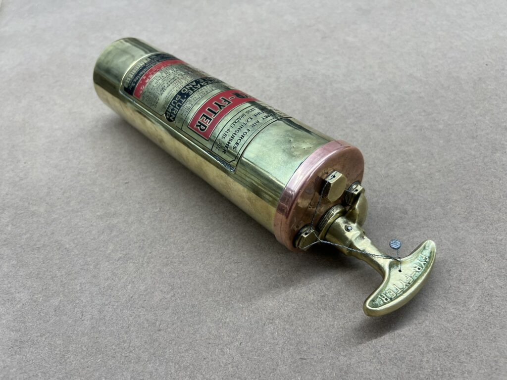
The extinguisher’s lock wire has also been replaced.
Photo taken 2024-4-8.
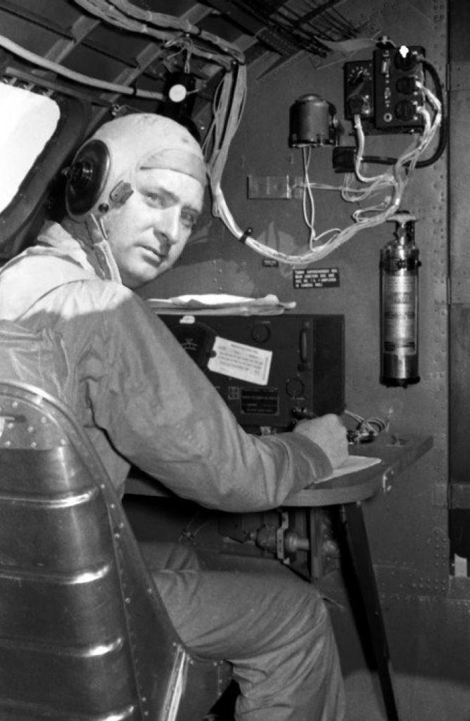
A radio operator aboard a fairly late B-17G peeks back toward the photographer.
A Type A-2 carbon tet extinguisher can be seen mounted on the Station 5 bulkhead to his right. F and G model B-17s carried a pair of carbon tet extinguishers on board, though the location of these units varied considerably.
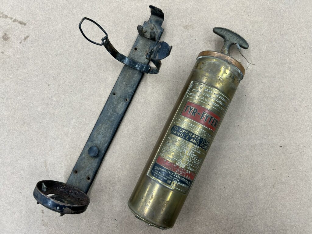
The recently restored Type A-2 carbon tet extinguisher as it appeared when it first arrived.
Unlike older models with “Army Air Corps” markings, “Army Air Forces” A-2s tend to have copper cap pieces rather than brass.
Photo taken 4 April 2024.
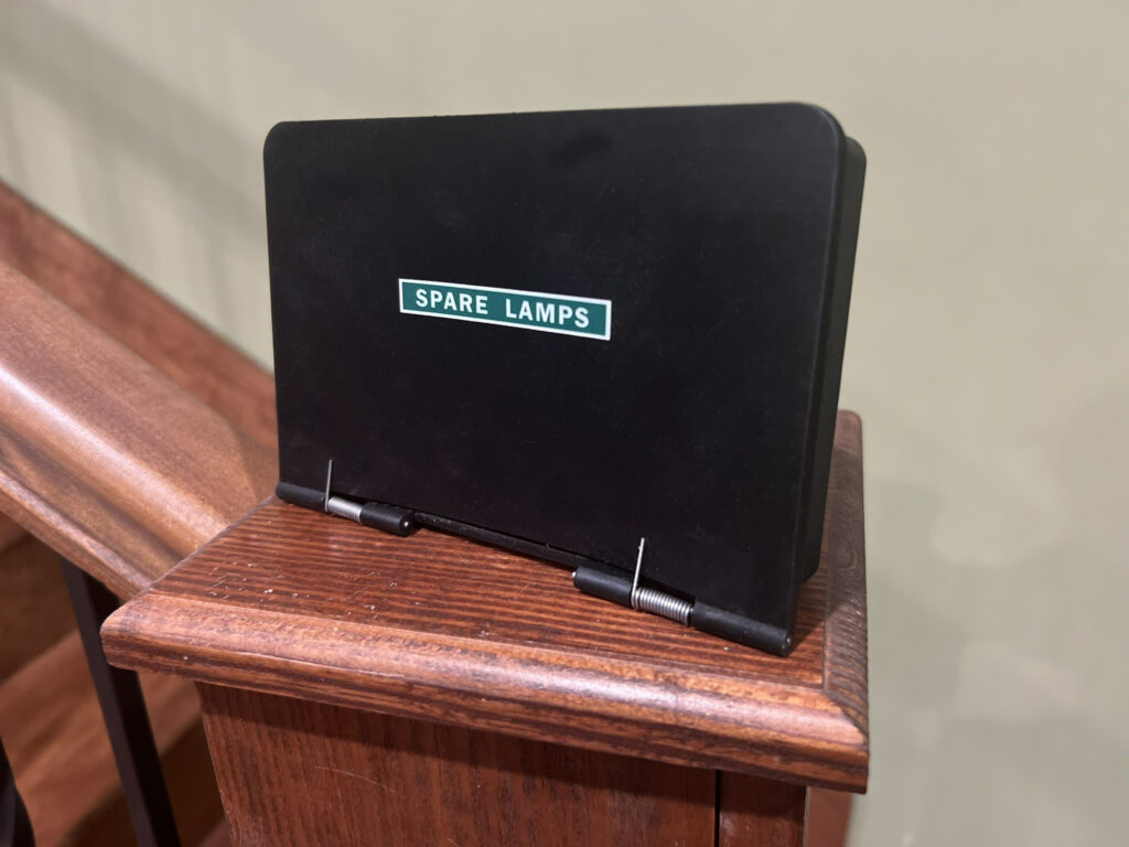
One of the three newly-completed Spare Lamp Boxes.
Photo taken 3 April 2024.
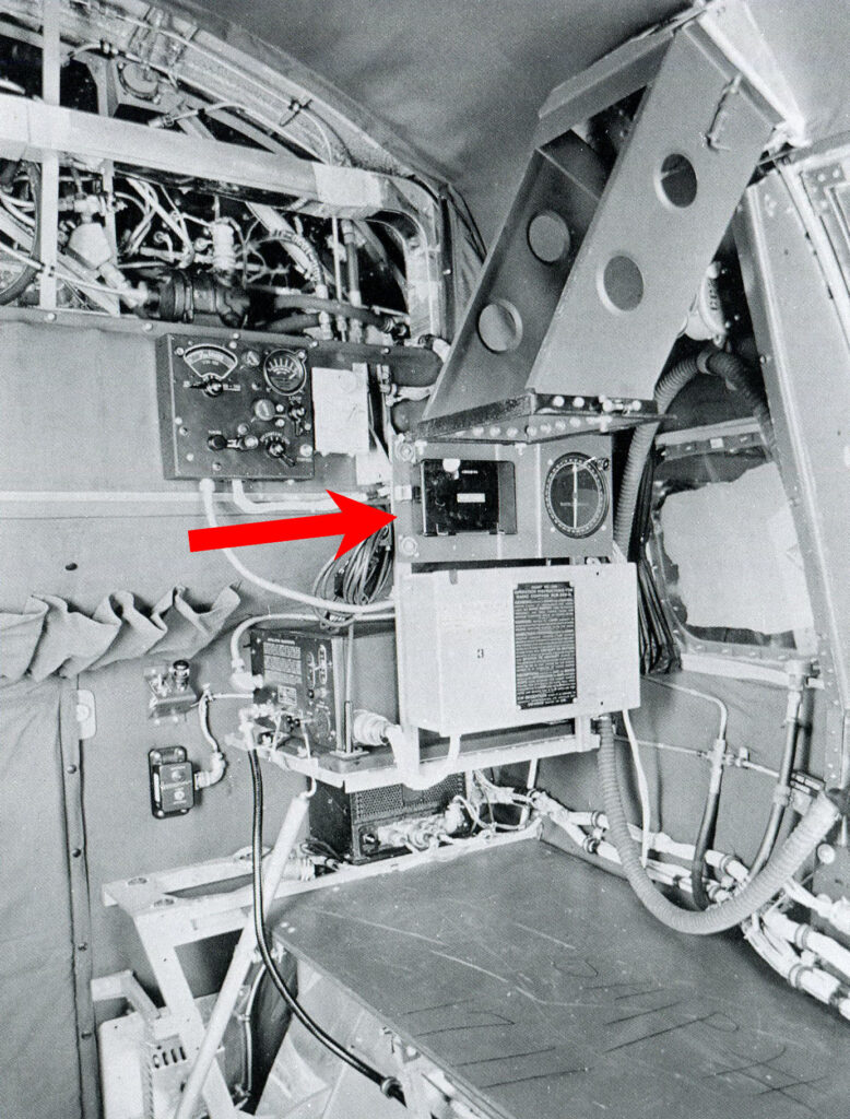
The Spare Lamps Box is highlighted beside the navigator’s position aboard a Boeing B-17F.
Note the large bracket assembly above the navigator’s table – this is one of the only photos showing the mount for the navigator’s astrograph aboard a B-17.
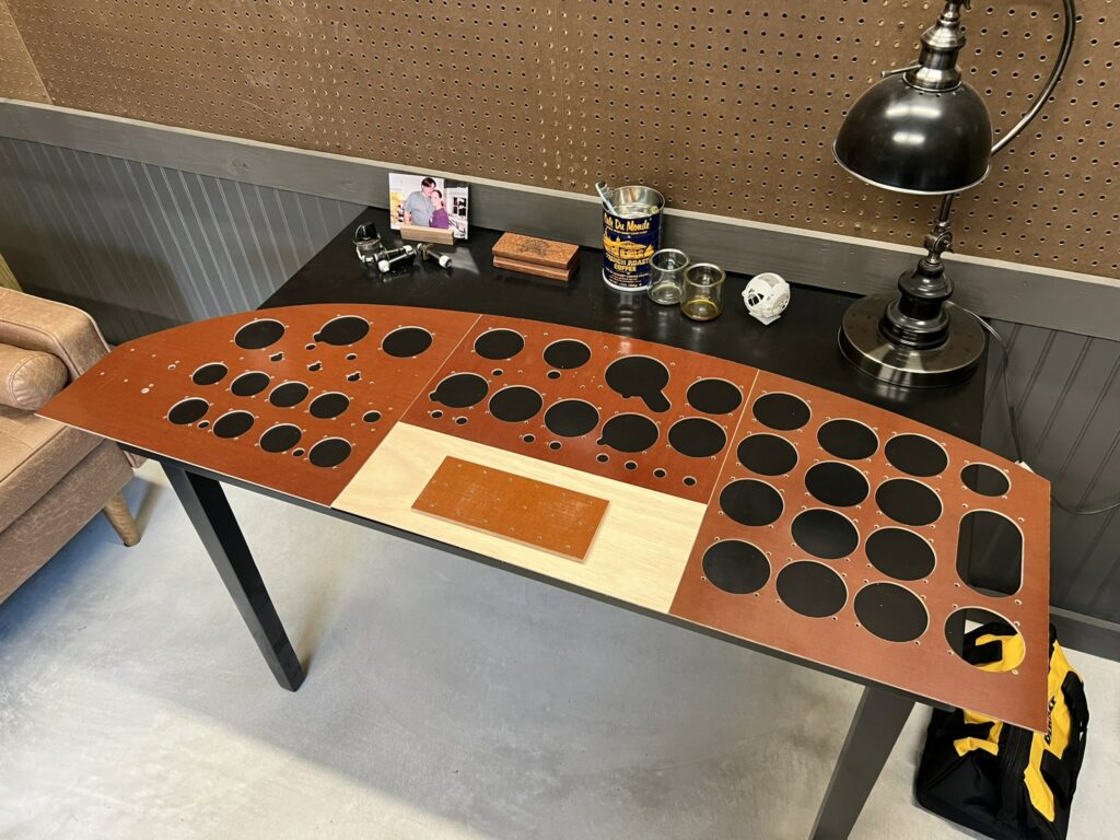
The phenolic faceplates for the instrument panel aboard Lucky Thirteen are finally cut.
Photo taken 19 March 2024.
Made a pilgrimage –
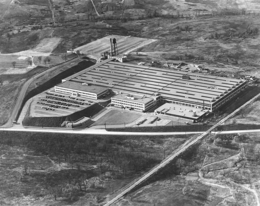
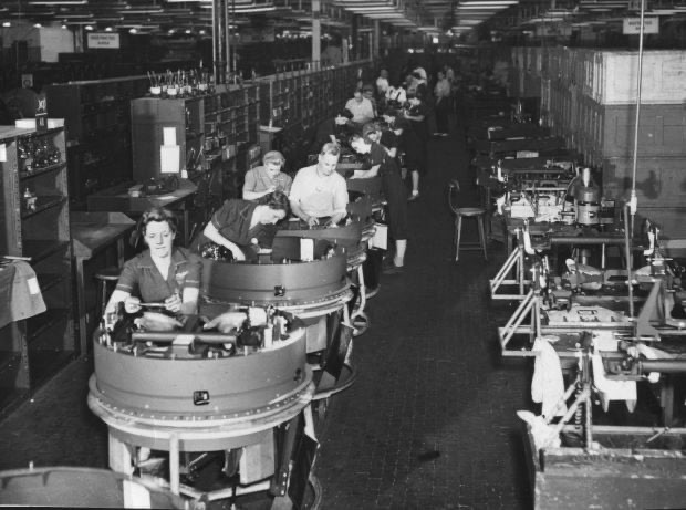
Visited the original Emerson Electric plant, where the Type A-1 Upper Turret on Lucky Thirteen was manufactured in 1943.
Located in Ferguson, Missouri (a St Louis suburb), Emerson was originally a desk fan company, but grew to become the single largest manufacturer of aircraft gun turrets. In fact, the first Secretary of the Air Force, Stuart Symmington, was Emerson’s wartime CEO.
Most of the original facility was torn down in 1995, and the plant was closed when I visited, but nevertheless we stopped and took a couple pictures.

I thought everyone might enjoy seeing these pics from Ray. The tail wheel assembly for Boeing B-17G Liberty Belle is finished and will soon be delivered to the Liberty Foundation in Douglas, Georgia.
