
It is always a joy for us when bringing forth something that has not been seen since the war. This is another one of those pieces – we now have the oxygen line for Lucky Thirteen‘s Type A-2 Ball Turret.
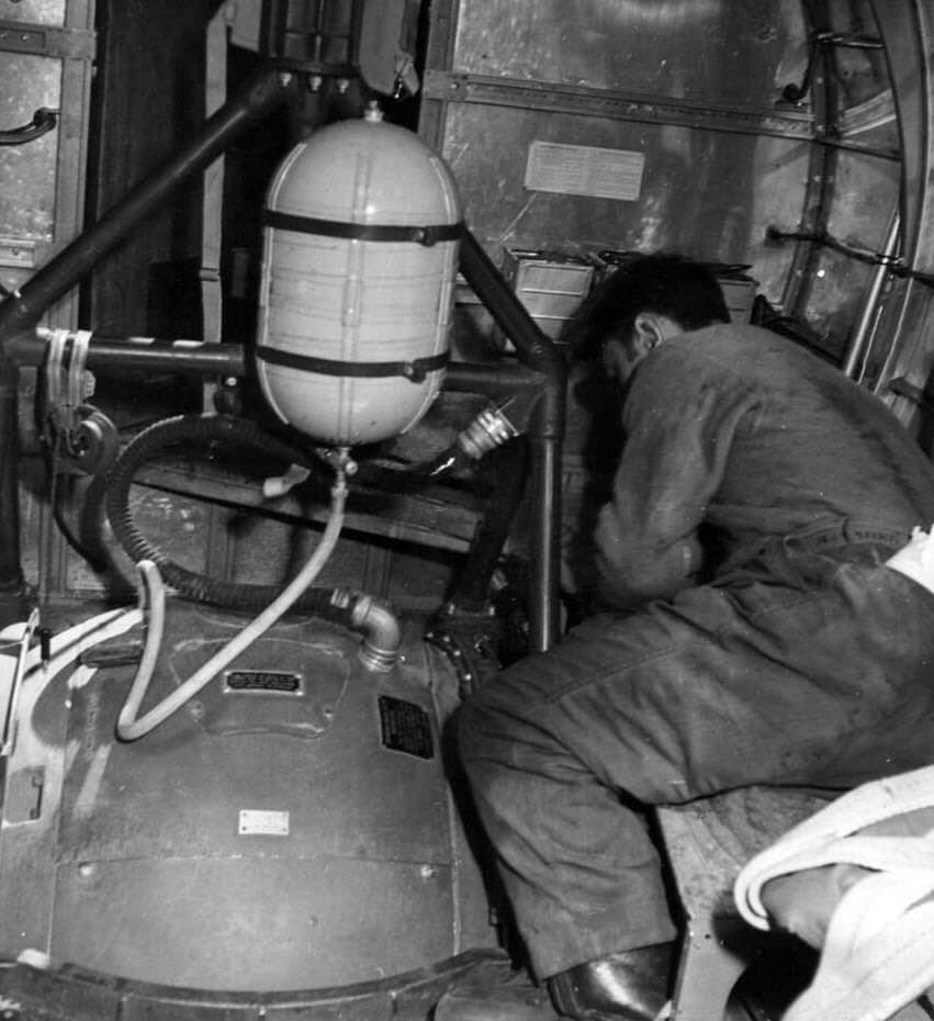
As mentioned in our previous update, museums and restorations regularly hang oxygen tanks on their ball turrets despite it being inaccurate for their aircraft. In late-1943, ball turrets with oxygen swivel joints were introduced, negating the need for an external tank. The Type F-1 Oxygen Tank, which the Sperry turrets were designed to use, held roughly half the capacity of the standard G-1 tank. As such, turret gunners had to keep an eye on their oxygen pressure. When the tank ran low, it was recharged using one of the lines used for recharging walkaround bottles. For the ball turret, this line is just beside the left waist gunner, near the reel antenna.
The fittings required some interesting research, as our references here predated the Army-Navy system so common in the warbird community. Special thanks to our friend Steve Salinas at Planes of Fame for his help researching these pieces. The oxygen line was custom made and donated by Custom Hose & Supplies of Cedar Rapids, Iowa. They did a beautiful job matching the manual spec. Thanks guys!


The newly completed ball turret oxygen feed.
The silver piece on the left is the nipple for recharging the oxygen supply. On the right is a plug for ground personnel to empty the tank.
Photos taken 14 June 2025.
A nice comparison photo showing the oxygen fittings on a Type A-2 Ball Turret.
Judging by the radio gun ammo cans near Station 6, this is most likely an early-B-17F.
Note the color of the oxygen line – we have found examples of both natural and black rubber hoses on these turrets.
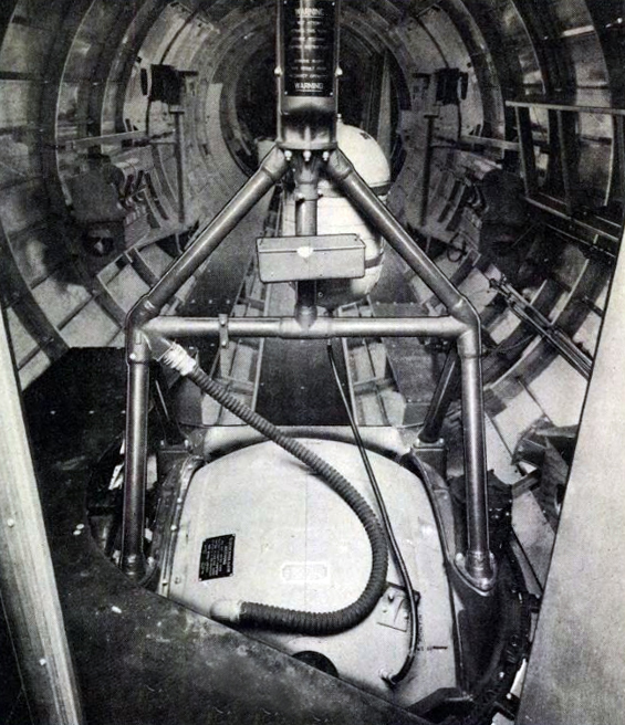
A Type A-2 ball turret aboard an E or early-B-17F, based on the waist configuration.
The ball on Lucky Thirteen was identical to what is shown here.
Next step, the bands which hold on the tank to the hanger assembly!
Speaking of the ball turret, another recent arrival is a partial example of the turret’s entry hatch.
This will be helpful as, if we are to cast a new ball (which seems the only likely way forward), the hardware here will prove invaluable.
This piece was purchased thanks to funds raised by our supporters and is currently with volunteer Bob Hachmann for reference in reverse-engineering our ball turret 3D scans. While it is theoretically possible to cast from these scans right away, we must proceed carefully as the castings will require precise machining once complete.


The newly-arrived partial ball turret hatch, with handle assembly for the missing side.
Photos taken 29 April 2025.
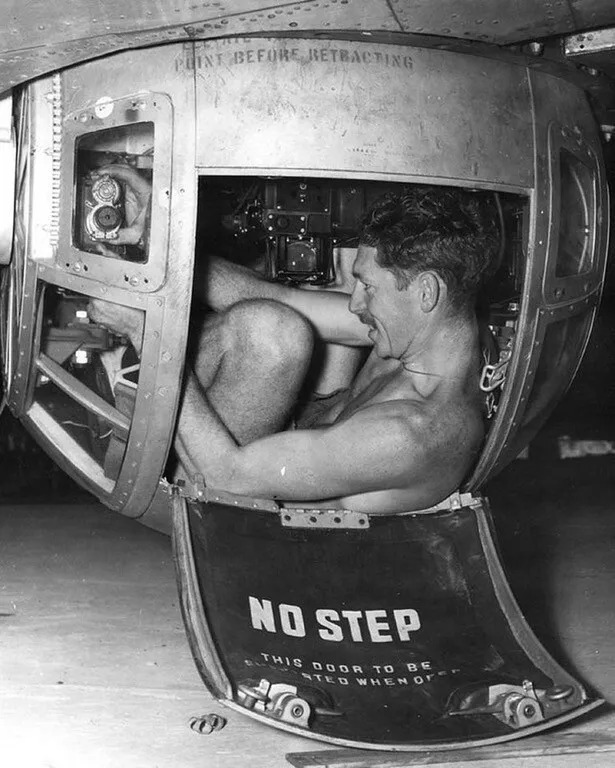
A serviceman of the Royal Australian Air Force adjusts the Type G-11 Solenoid aboard a Type A-13 Ball Turret. The Type A-13 was the ball turret variant installed aboard Consolidated B-24D through Js.
Note the entry hatch below. The entry hatch and the armor plate it is bolted to were both covered in dark green vinyl.
Another recent purchase, made possible by our supporters, was a complete set of fuel caps for Lucky Thirteen‘s wings.
These came to us from Dan Dimon of Tulsa, Oklahoma, who once lived near the boneyards of Kingman, Arizona. These caps are labelled as to quantity, meaning that each one is meant for a specific tank. In general, the standard Boeing B-17 carried a single fuel tank for each engine, with a third feeder tank behind each pair. However, starting with Boeing block F-80, the B-17 also came with a series of outer-wing tanks colloquially known as “Tokyo Tanks.” While each set of Tokyo Tanks was comprised of nine rubber bladders, the manner in which they were plumbed only required two additional fuel caps.
In total, Lucky Thirteen carried 2,780 gallons of fuel when fully loaded, laid out thusly:
Outboard Engines – 425 Gallons Each
Inboard Engines – 213 Gallons Each
Inboard Engine Feeder Tanks – 212 Gallons Each
Tokyo Tanks – 270 Gallons for Each Engine
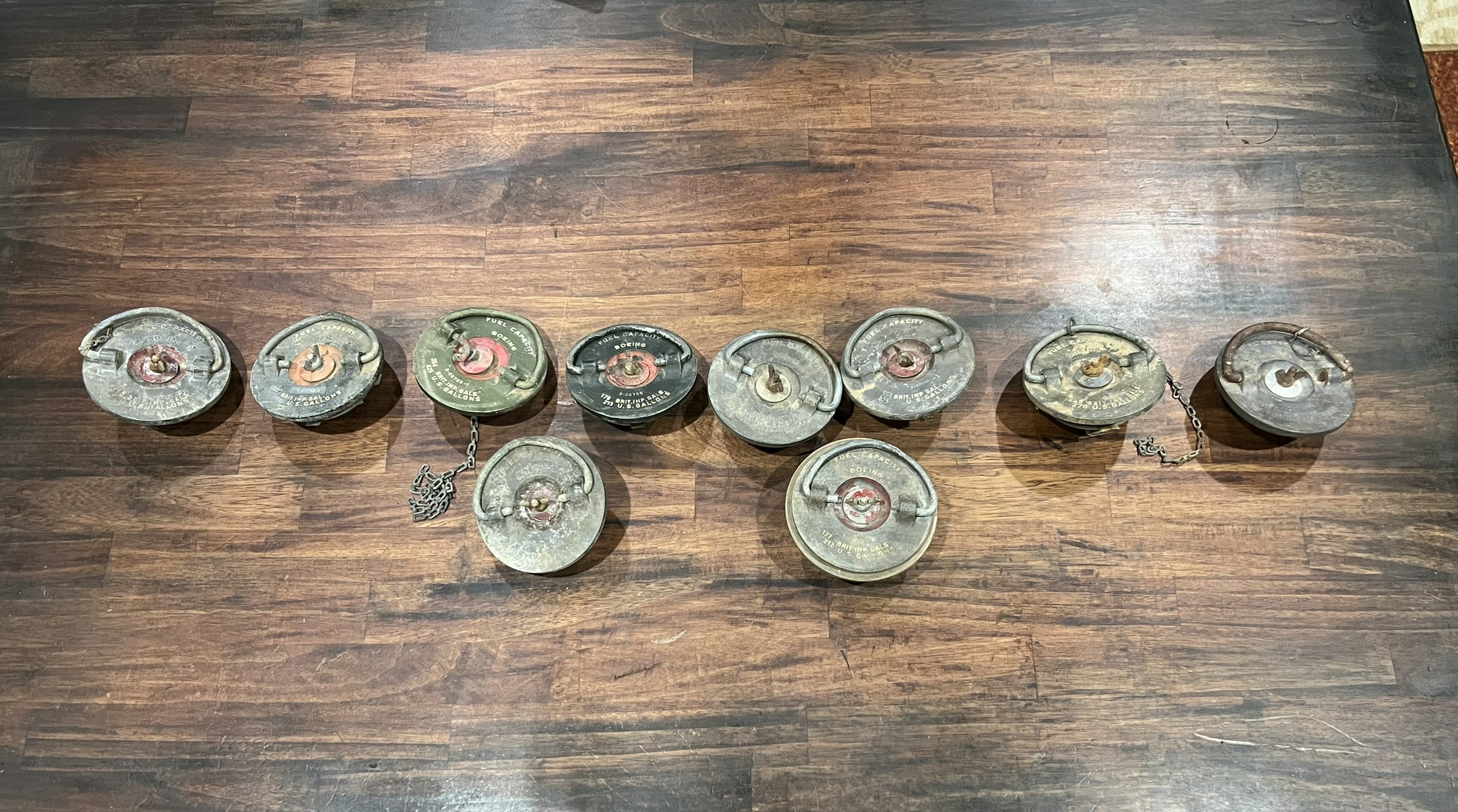
The newly arrived fuel tank camps, aligned roughly as they would be on the real thing.
Photo taken 24 May 2025.
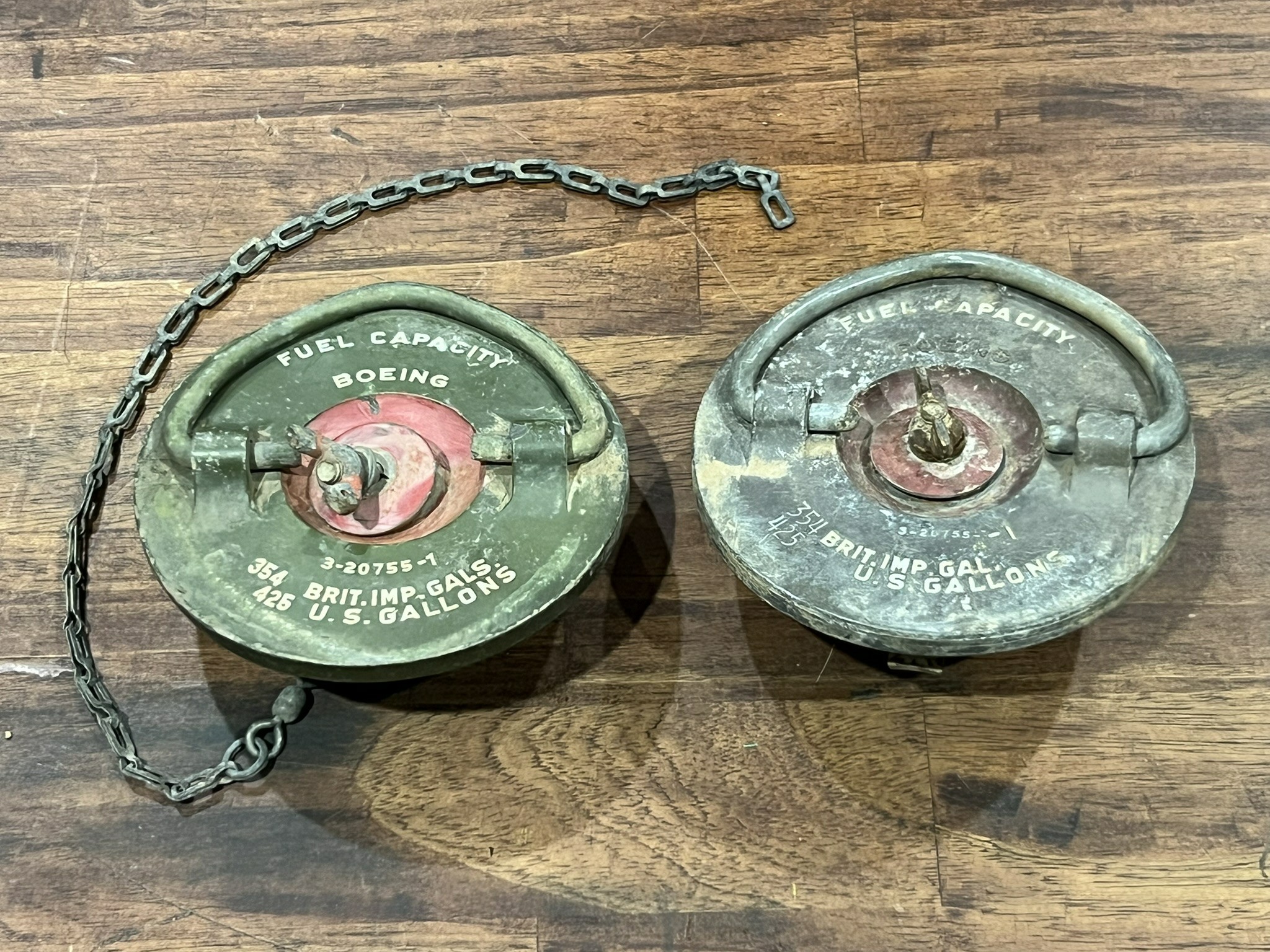
A close-up of the fuel caps for the outboard engine fuel tanks.
Note how the caps are labeled, not only with part numbers, but for the quantity of fuel in the tank in both US and British Imperial Gallons.
Photo taken 24 May 2025.
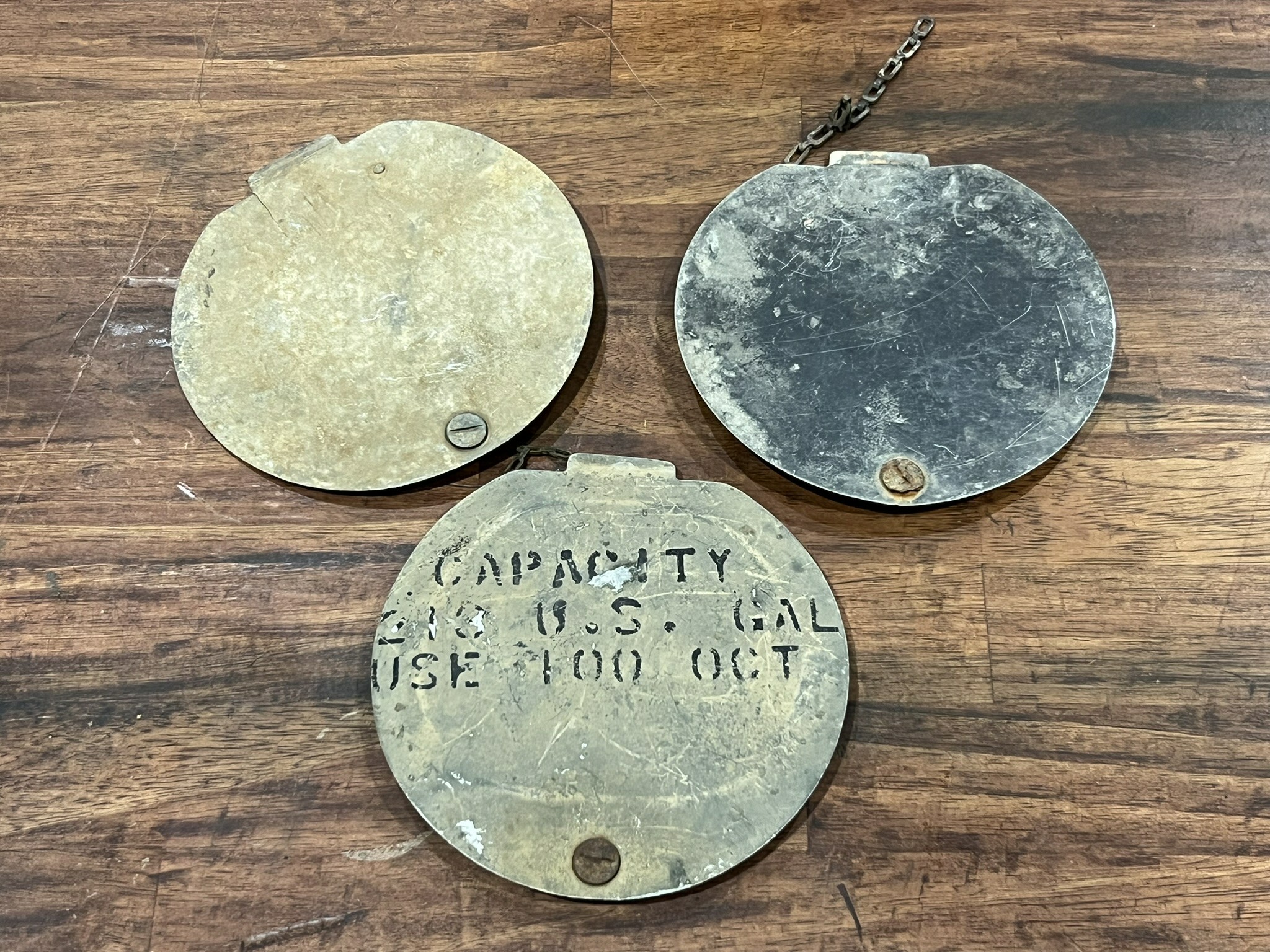
The aircraft’s fuel caps were not normally visible, being hidden underneath lids, held in place with Dzus fasteners.
Three surviving examples of these lids were included with our fuel caps.
Photo taken 24 May 2025.
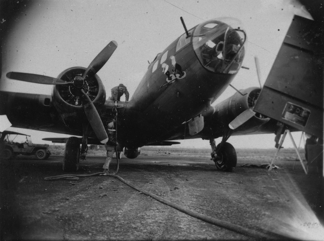
Ground personnel refuel one of the two tanks behind Engine No. 3 on Our Gang (42-5069, 91BG).
Our Gang was lost on the 17 August 1943 strike on Schweinfurt, Germany.
While work continues on the aft fuselages of Lucky Thirteen and the Lake Dyke B-17G, work is also resuming on Lucky Thirteen‘s bomb bay.
To review, the bomb bay is structurally the backbone of the B-17. The wing carry-thru spars constitute the lower halves of Stations 4 and 5 – i.e., the rear bulkhead of the cockpit and the forward bulkhead of the radio room – with the bomb bay catwalk and the outer compression struts of the two wings forming a giant, bed-frame type box. This “box” is what supports the weight of the entire aircraft.
So, while it may not be as readily recognizable as a nose or cockpit windscreen, it is from an engineering perspective, the place to start on any B-17.
Ray has decided to shift gears somewhat, temporarily removing the carry-thrus from underneath the stations and starting work on the skins which connect the roof of the bay (which is already in place) to the outer compression struts of the frame assembly below. This will entail work on the channel assemblies which reinforce the aircraft’s bomb racks, extending them down as well. Like the aft fuselage, when completed, visitors will be able to literally step inside Lucky Thirteen‘s bomb bay.
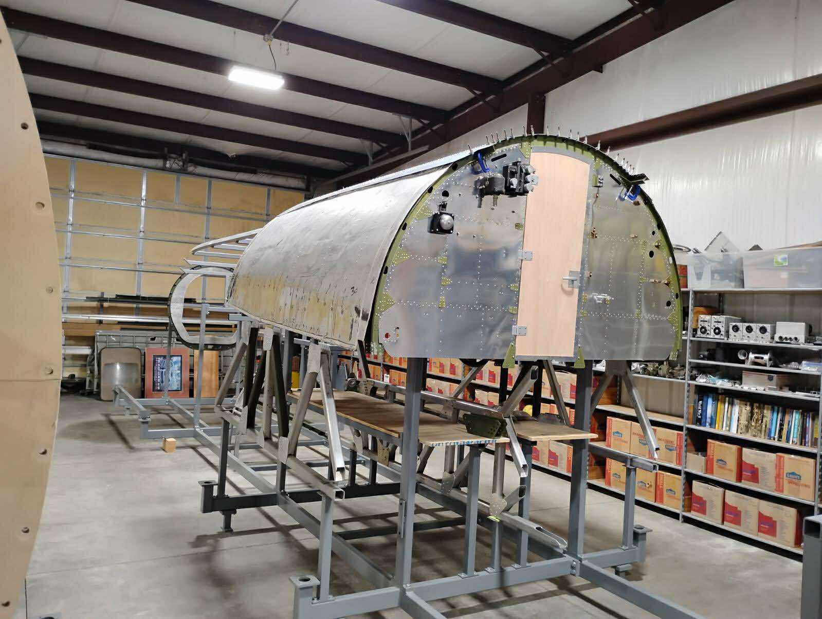
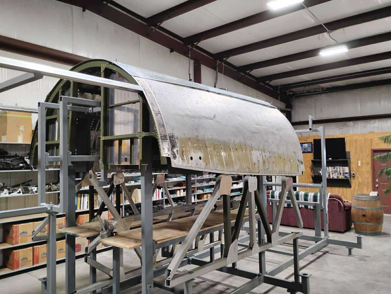
The outer compression struts are returned to the jig and original skins laid in place for alignment. This view is from Station 5 looking forward.
If the door looks different, that is because it is – the original door was damaged when we changed buildings. Thankfully, we had a spare. It just needs to have its clearcoat applied.
Station 3, the bulkhead that is the back of the nose compartment, is not present here. It has been removed from the jig to have its zinc chromate and ALCLAD stamps applied.
The SCR-274 radio shelves are generally removed from Station 5 while working in the shop.
Photo taken 6 June 2025.
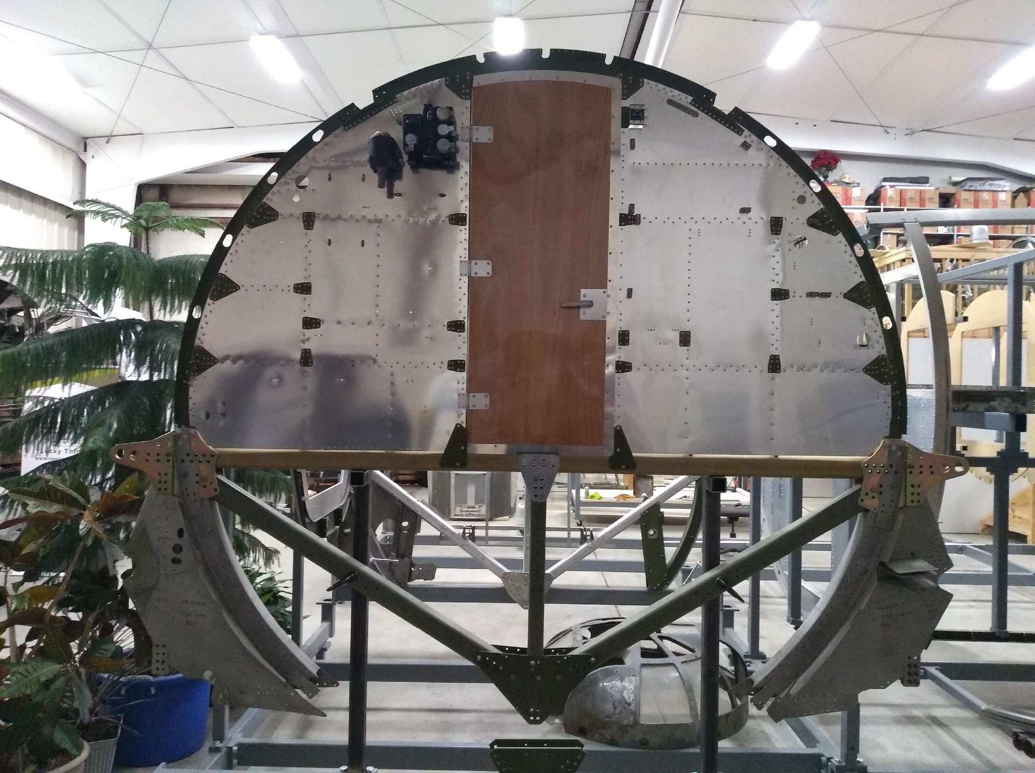
The outer compression struts are returned to the jig and original skins laid in place for alignment. This view is from Station 4 looking forward.
The forward fuselage jig comprises Stations 1 through 6. Station 2 was not a bulkhead and cannot be mounted independently. The original Station 6 pattern will be mounted to the jig soon.
Fun fact: the Station 4 and 5 bulkheads do not mount perfectly straight. They actually tilt back toward the tail, leaning from the base at 3°. They are the only Stations on the B-17 which do this.
Photo taken 6 June 2025.
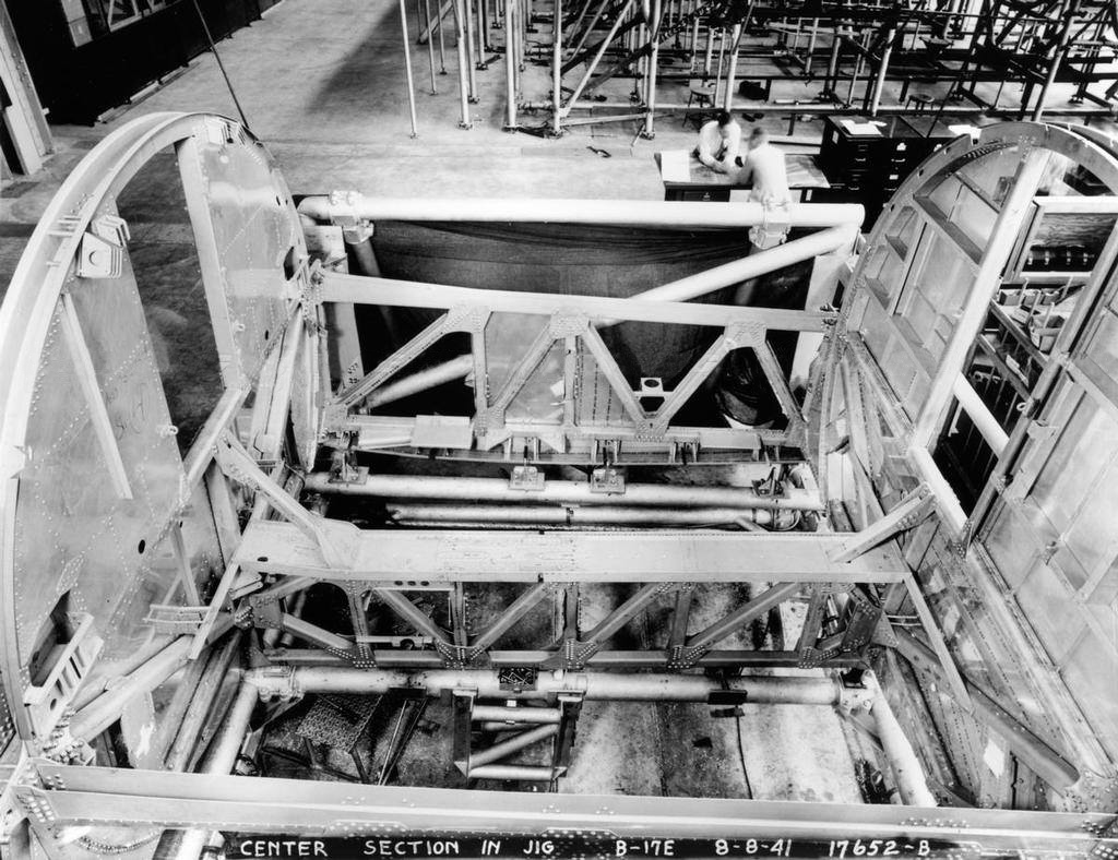
Boeing factory photo of a B-17E bomb bay section, the outer compression struts and bomb bay catwalk affixed to the carry-thrus under Stations 4 (left) and 5 (right).
Photo taken 8 August 1941.
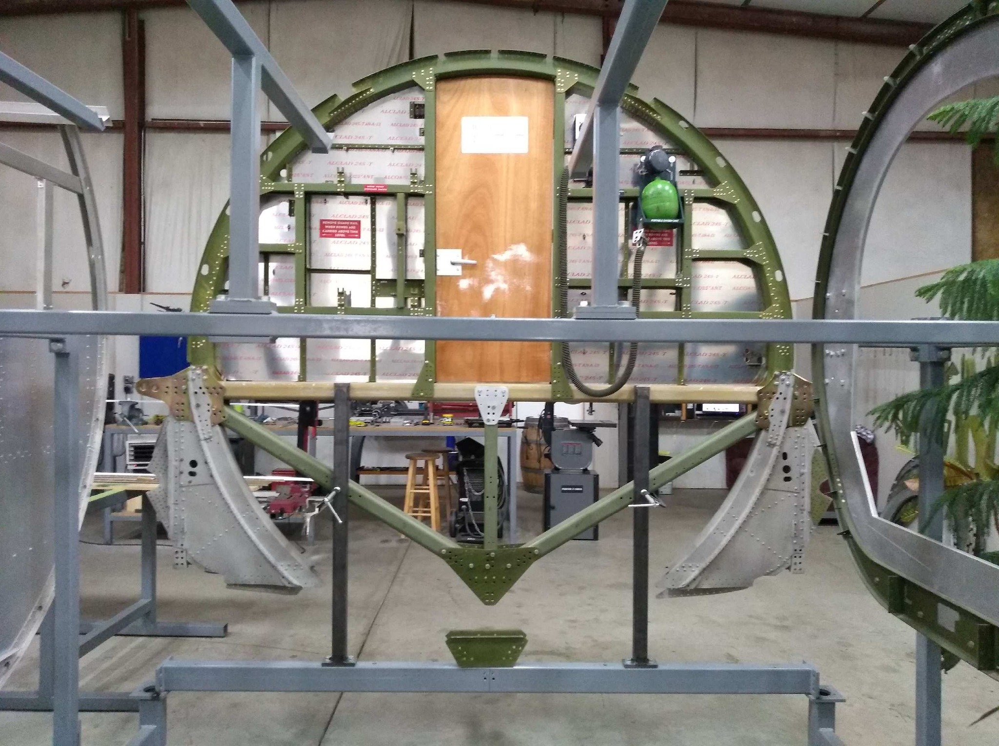
The carry-thrus temporarily mounted to Station 5 for fitting.
The carry-thrus for Station 4 are currently in a similar state, with one side finished and the other original to show a before-and-after for visitors.
Photo taken 21 February 2024.
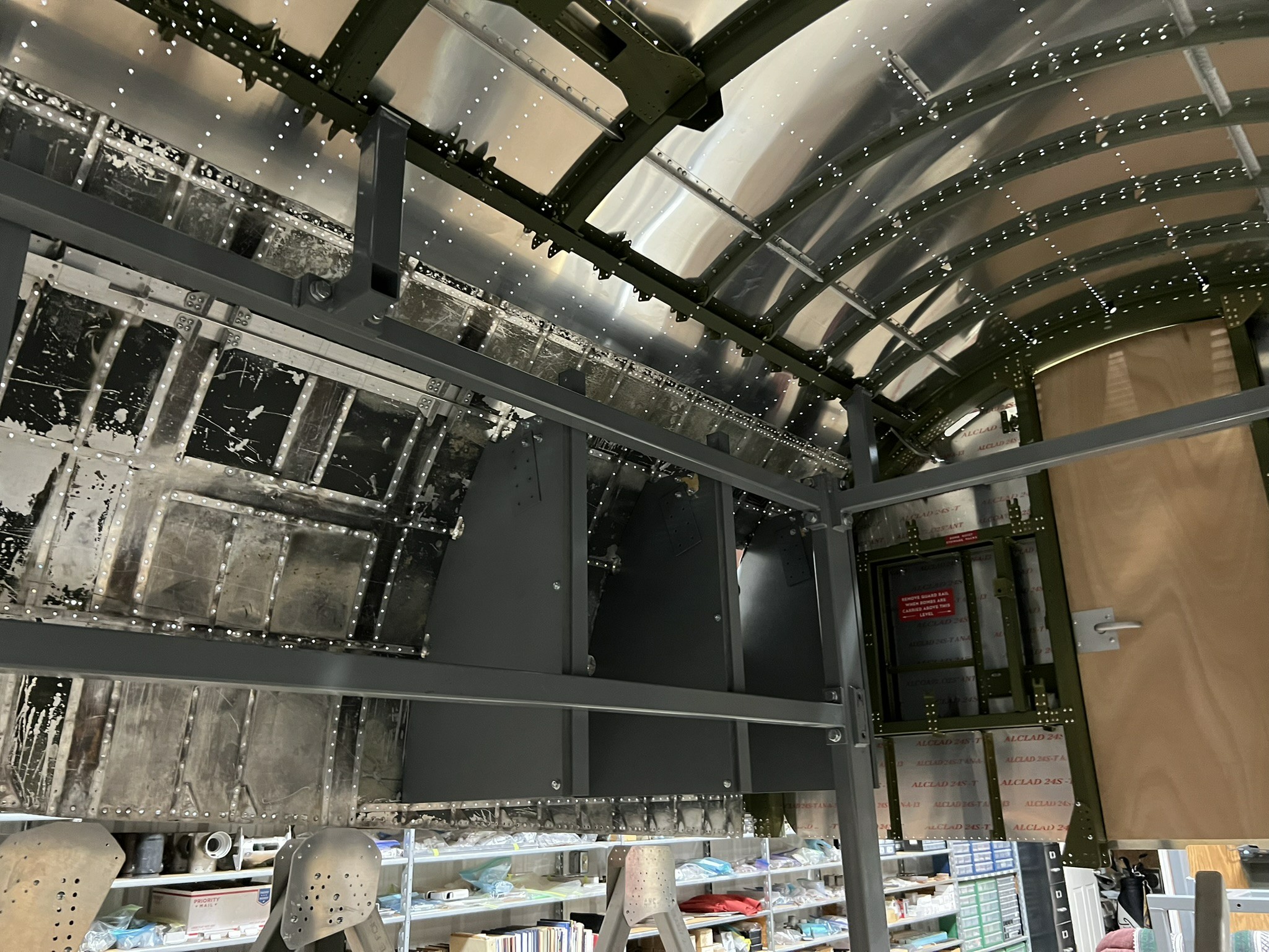
Standing inside the bomb bay, looking at the new skins and the original skins now temporarily attached to one another. The ceiling of the bomb bay was not exposed to the outside air, as it was hidden by the upper “turtle deck.” The turtle deck above the bomb bay held the aircraft’s two emergency life rafts.
Photo taken 6 June 2025.
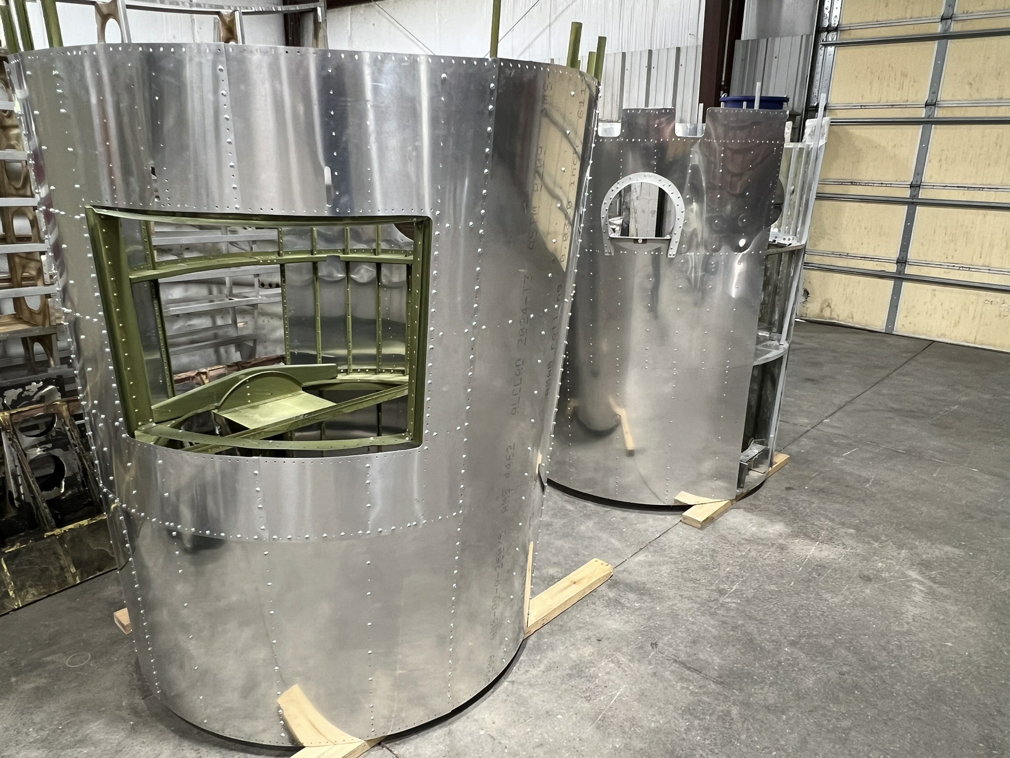
Stations 10 and 11 of the Lake Dyke B-17G (left) and Lucky Thirteen (right), awaiting their turn to be reattached to their respective aft fuselages.
Photo taken 9 May 2025.
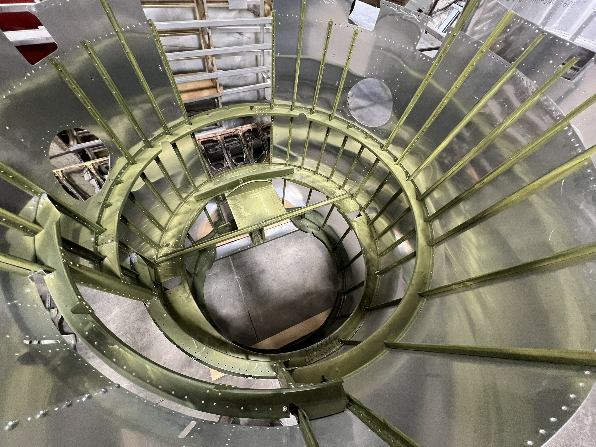
Looking inside Stations 10 through 11 in the Lake Dyke B-17G fuselage section.
True to Douglas practice, the ribs and stringers have been dipped in zinc chromate. The ALCLAD stamps have not yet been applied to the bare skins.
Photo taken 9 May 2025.
Another recent arrival is the instrument panel for the bombardier’s panel assembly. This piece comes to us from the team at B-17E Desert Rat (41-2595).
The panel assembly to the B-17 bombardier’s left side was divided into sections, comprising the bomb intervalometer, bomb rack indicator panel, primary control panel, and instrument panel. The instrument panel contained repeater gauges for airspeed and altitude, a clock, and on some aircraft, a thermometer. These instruments were to be shared by the bombardier and navigator.
A rather thick piece of aluminum, the team at the Rat were kind enough to press this piece for us. Next step will be to drill a few additional holes and polish the metal thoroughly in preparation for its blackening.
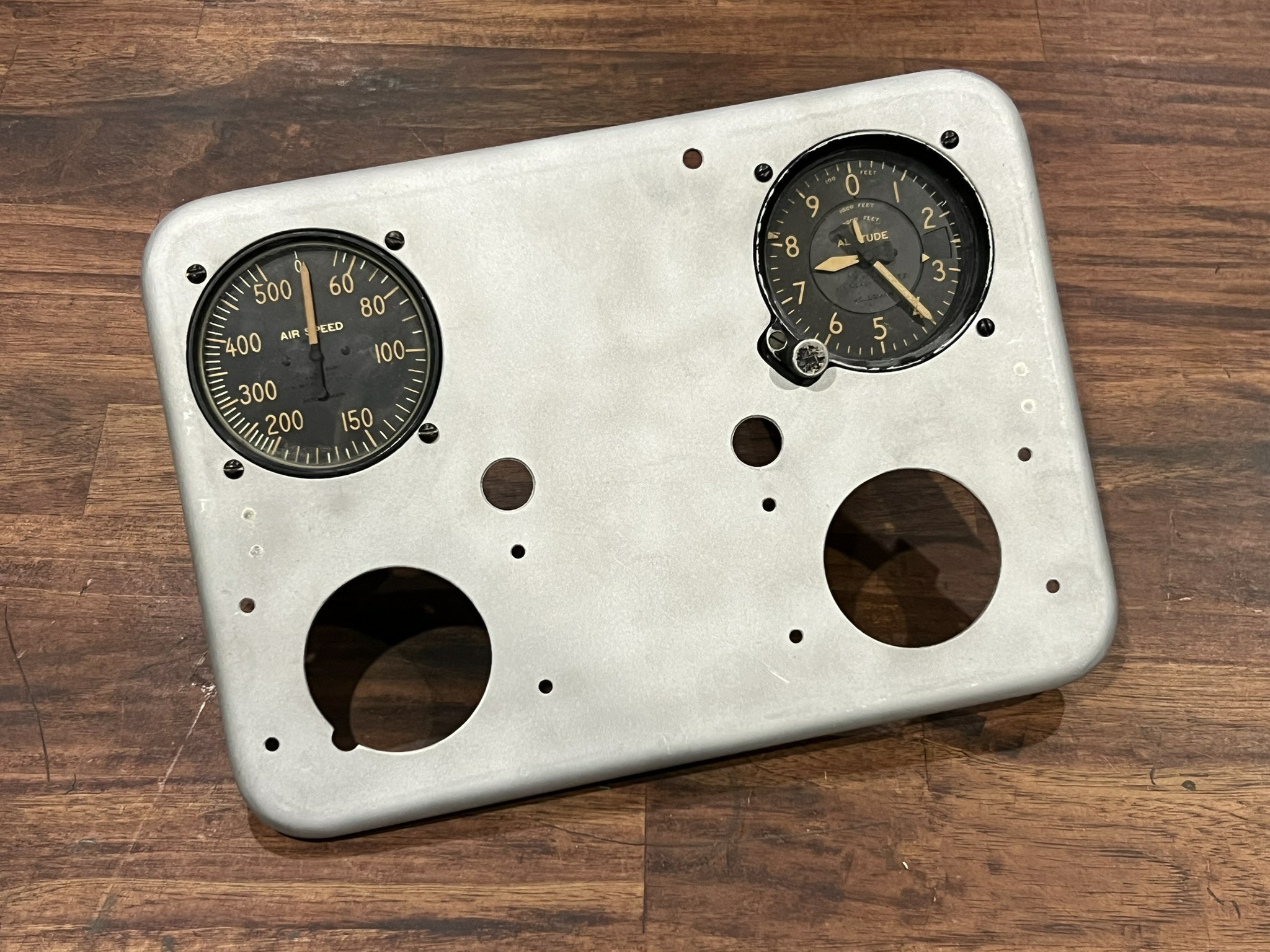
The newly arrived bombardier’s instrument panel section.
Photo taken 20 May 2025.
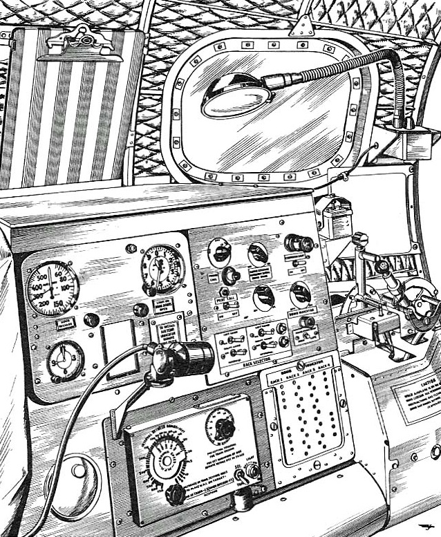 Manual illustration of the bombardier’s panel assembly aboard a B-17F.
Starting from the top left, moving clockwise, the panels are: the instrument panel, control panel, bomb rack indicator panel, bomb intervalometer, and ashtray. Based on the layout of the control panel, this is an aircraft slightly older than Lucky Thirteen.
The light assembly on the little arm is a UV light for making the markings glow in the dark.

The control panel assembly for Lucky Thirteen‘s bombardier panel.
The round object protruding from the upper right is an extension lamp, whose wire spools out when pulled from the panel.
Photo taken 31 July 2023.
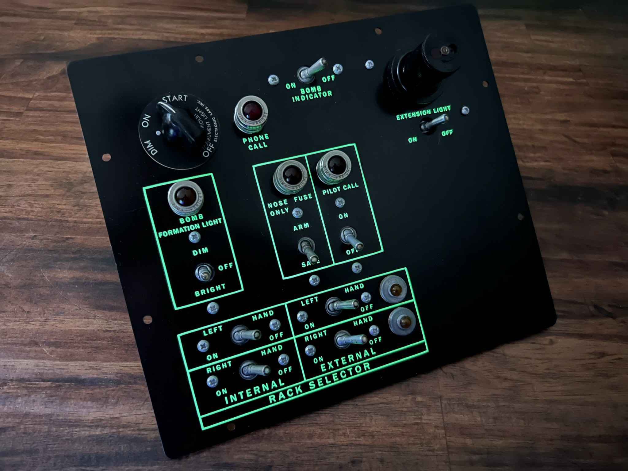
True to wartime practice, the markings on Lucky Thirteen‘s bombardier control panel are UV reactive.
The knob on the upper left is what controls the brightness of the UV light.
Photo taken 31 July 2023.
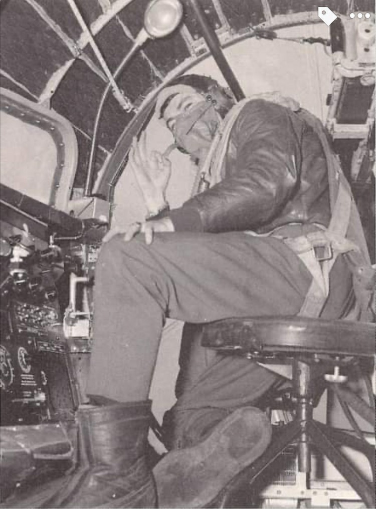
1Lt. Samuel M. Slaton of the 91BG. Note the bombardier’s panel to his left.
While the controls for his panel are different than those of Lucky Thirteen, virtually everything else aboard the nose compartment in this photo is identical.
Note the insulation here. The outer blankets have been removed from the walls due to the installation of the modified nose gun. Due to its taper, the nose was the only compartment in the B-17F whose insulation had a wavy-diamond stitch.
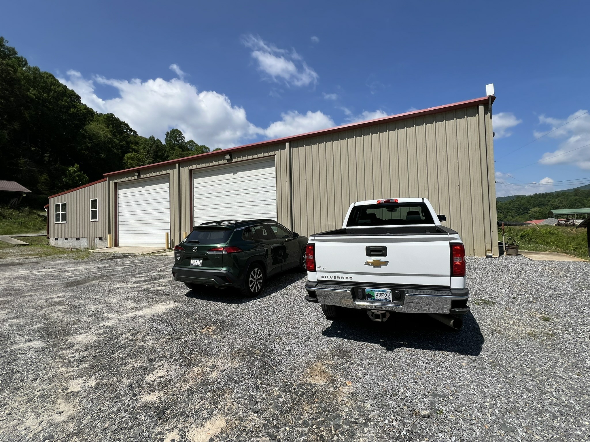
Last is a picture that I know many have been waiting for:
A shot of our new location!
The Hangar Thirteen Foundation is a 501c3 nonprofit charity and donations toward this project are tax deductible. If you can spare a little to help this project, you can guarantee that you will see the results on Facebook and here on our website.
You can contribute through the Donate page or, to avoid a PayPal fee, you can send something via the mail to:
Gerad Allen Blume
Hangar Thirteen Foundation
442 Old Chalk Bed Road
Batesburg, SC 29006
Volunteers are also always welcome. In fact, you need not be an Asheville resident – you can work from home! Persons skilled with metal fabrication, machining, CAD modeling, metal casting, 3D scanning, and laser/waterjet cutting, are particularly helpful. Just reach out to us to get started.
Keep the show on the road!