
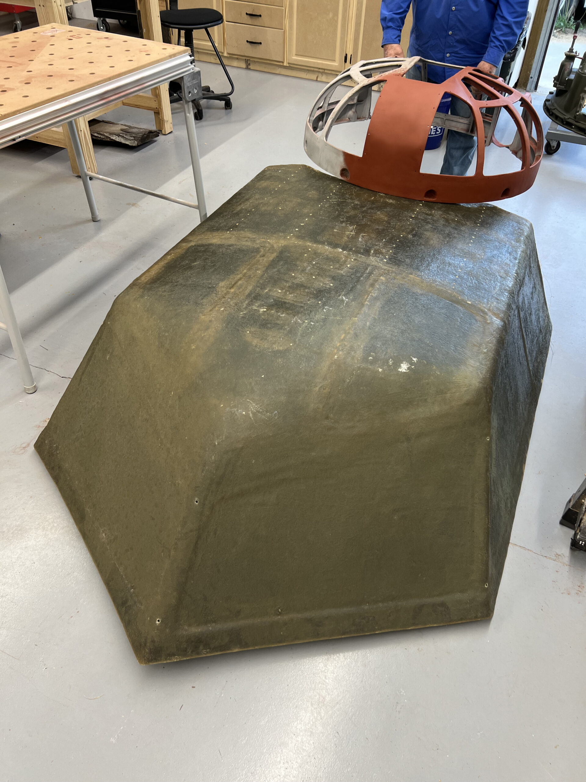
Lucky Thirteen‘s top turret dome is held in place against the mold for the cockpit canopy.
This mold will be used to press the curves here into the aircraft aluminum.
Photo taken 7 April 2026.
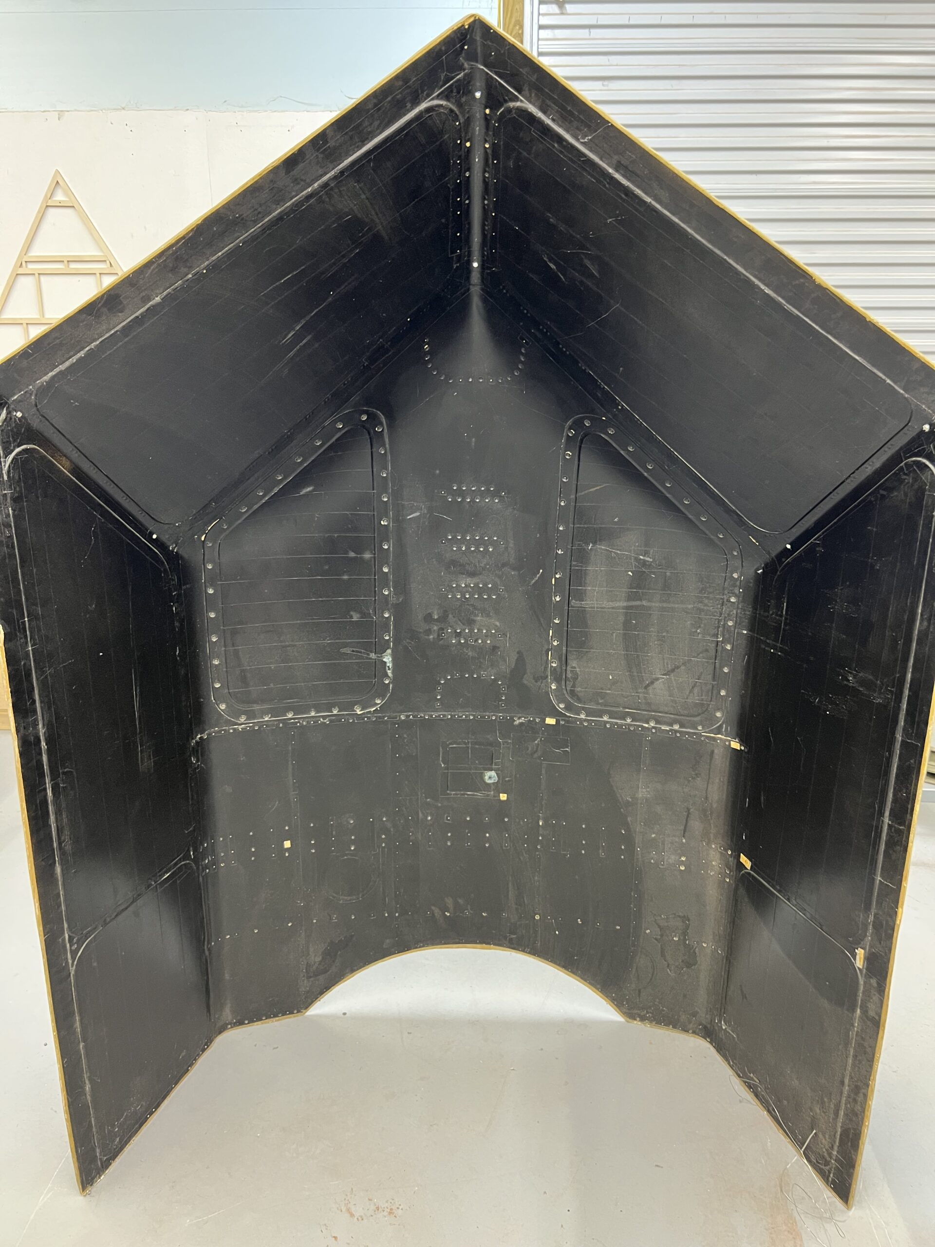
The inside of the cockpit canopy mold. The layout of the forward, side, and upper window can be seen here, as well as the location for the flare gun bracket.
The B-17G’s cockpit canopy was dual layered, while the B-17F was single. In doing so, the B-17F required a series of braces be installed to support the overhead panels. These included the compass panel, SCR-274 Command Radio controls, SCR-269 Radio Compass controls, and the aircraft’s emergency brake. The latter was unique to B-17Fs.
Photo taken 13 April 2026.
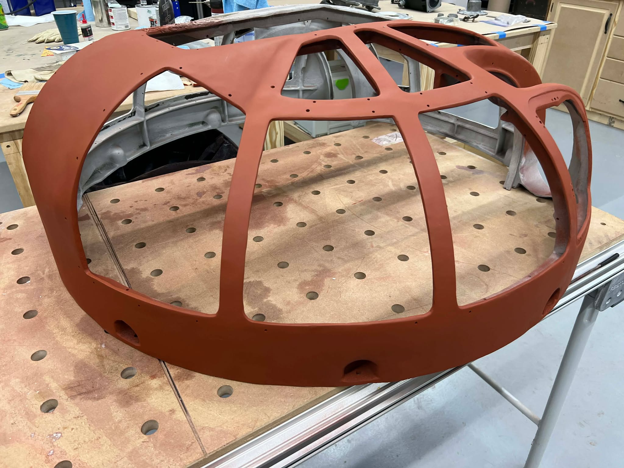
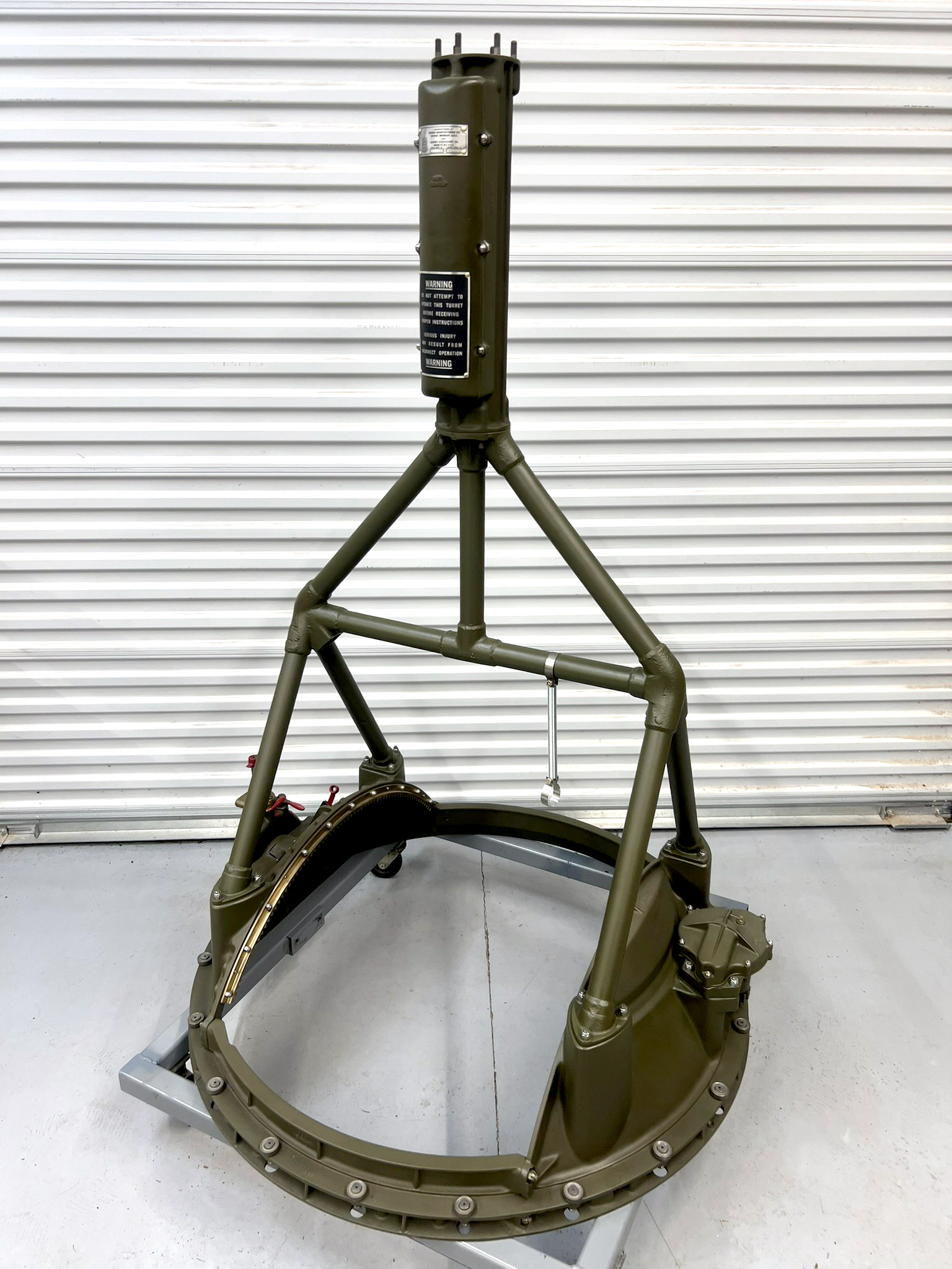
With the A-1 Upper Turret dome repaired, I can being work refinishing this piece.
While it is true that Emerson used yellow chromate as its primer, at the moment I am using the same red as used on the Briggs trunnion assembly. This is because yellow primer is rather expensive and lacks a filling agent. So, I will wait until happy with the finish before spraying the yellow on.
I am slowly working my way around, starting from the back.
Photo take 23 March 2026.
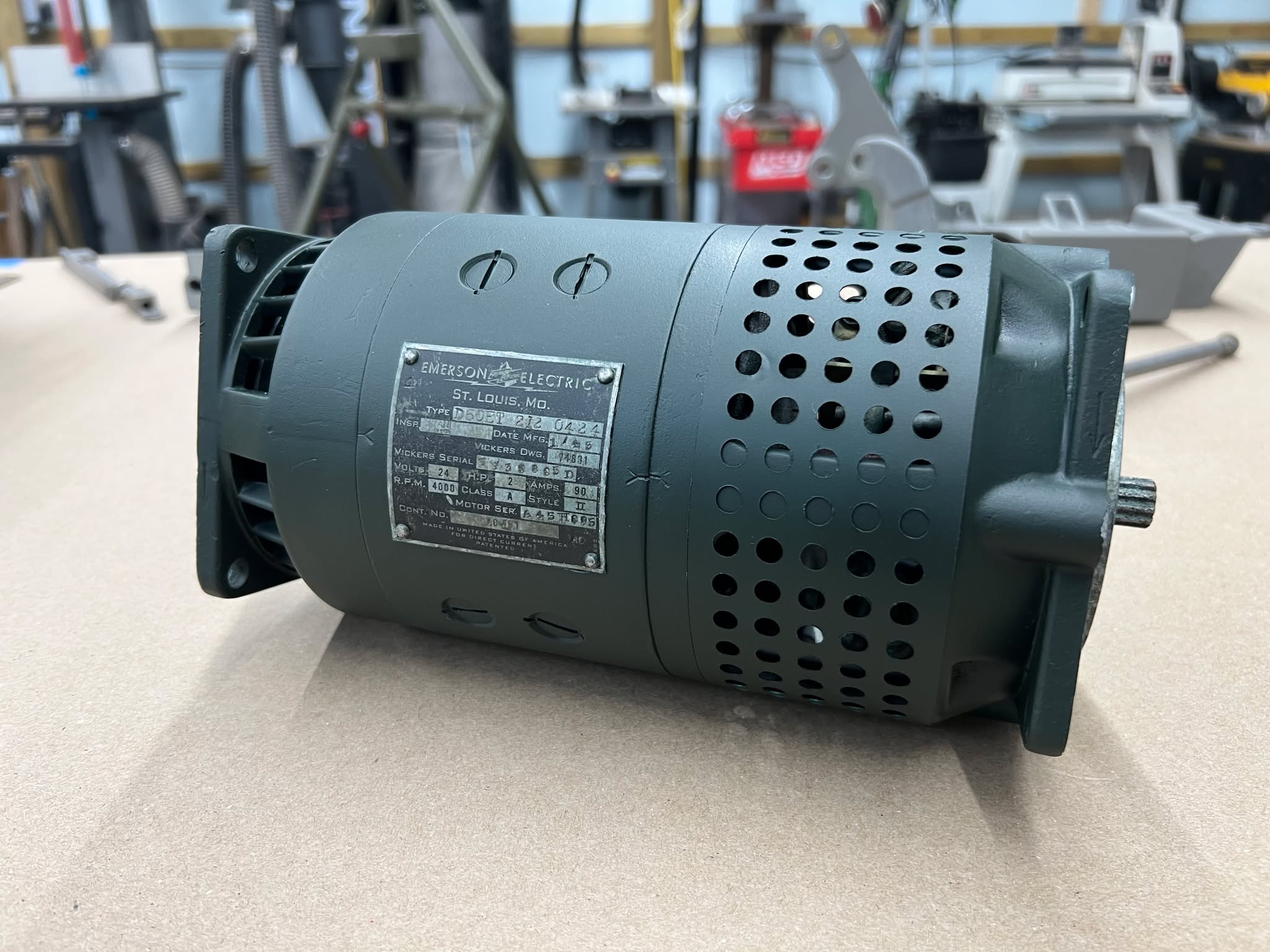
So far, we have yet to receive our turret motors back from Fred the Turret Guy.
In the meantime, Fred offered to swap a previously restored Emerson of his with our own. I just had to refinish it.
Well, here it is, refinished using a paint color-matched to the green used by Emerson Electric. This is the same green used throughout the entirety of the A-1 Upper Turret.
Photo taken 12 May 2026.
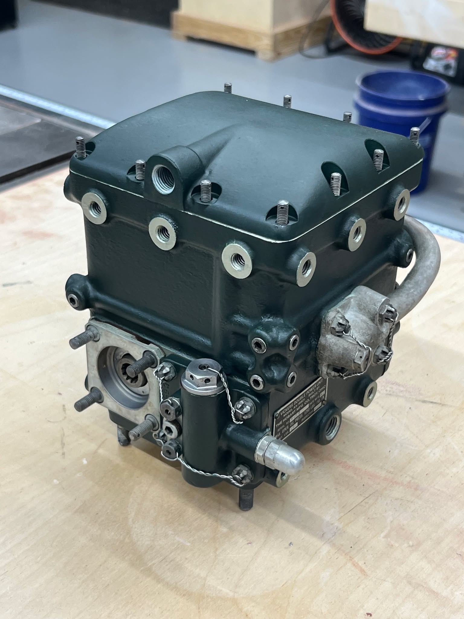
That being the case, I decided to dig out a transmission that we had set aside specifically for the top turret.
A unique characteristic of Sperry turrets, these transmissions were largely produced by their Detroit-based subsidiary, Vickers. When Emerson Electric offered to supplement Sperry turret production in the face of SPECO and Briggs not being able to meet A-1 and A-2 turret (respectively) quotas, the Sperry Double Power Unit became an important bottleneck.
Emerson was willing to make their own Double Power Units – which is fully evident by the electric motor previously noted. Emerson CEO Stuart Symington’s blustering had already flared up tensions with Briggs regarding ball turrets and it did so again with Vickers over transmissions, threatened legal recourse over patent infringement. The Army intervened, contracting Hobart of Troy, Ohio to also build Sperry turret transmissions. Hobart, who manufactured kitchen machinery, was seen as an acceptable compromise as other suggested licensees, like Delco, were peacetime market competitors.
Knowing this history, we really wanted to outfit our Emerson A-1 with an Emerson motor with Hobart transmissions. Unfortunately, we only have one Hobart, so we need one more to make this happen. If you happen to have a Hobart turret transmission and are willing to help the project, please let us know! The important thing is that it be relatively free from corrosion (grime is okay), that the little disc on the side still be able to turn, that turning said disc moves the piece hidden inside, and that the pin on the disc not be broken.
Photo taken 12 May 2026.
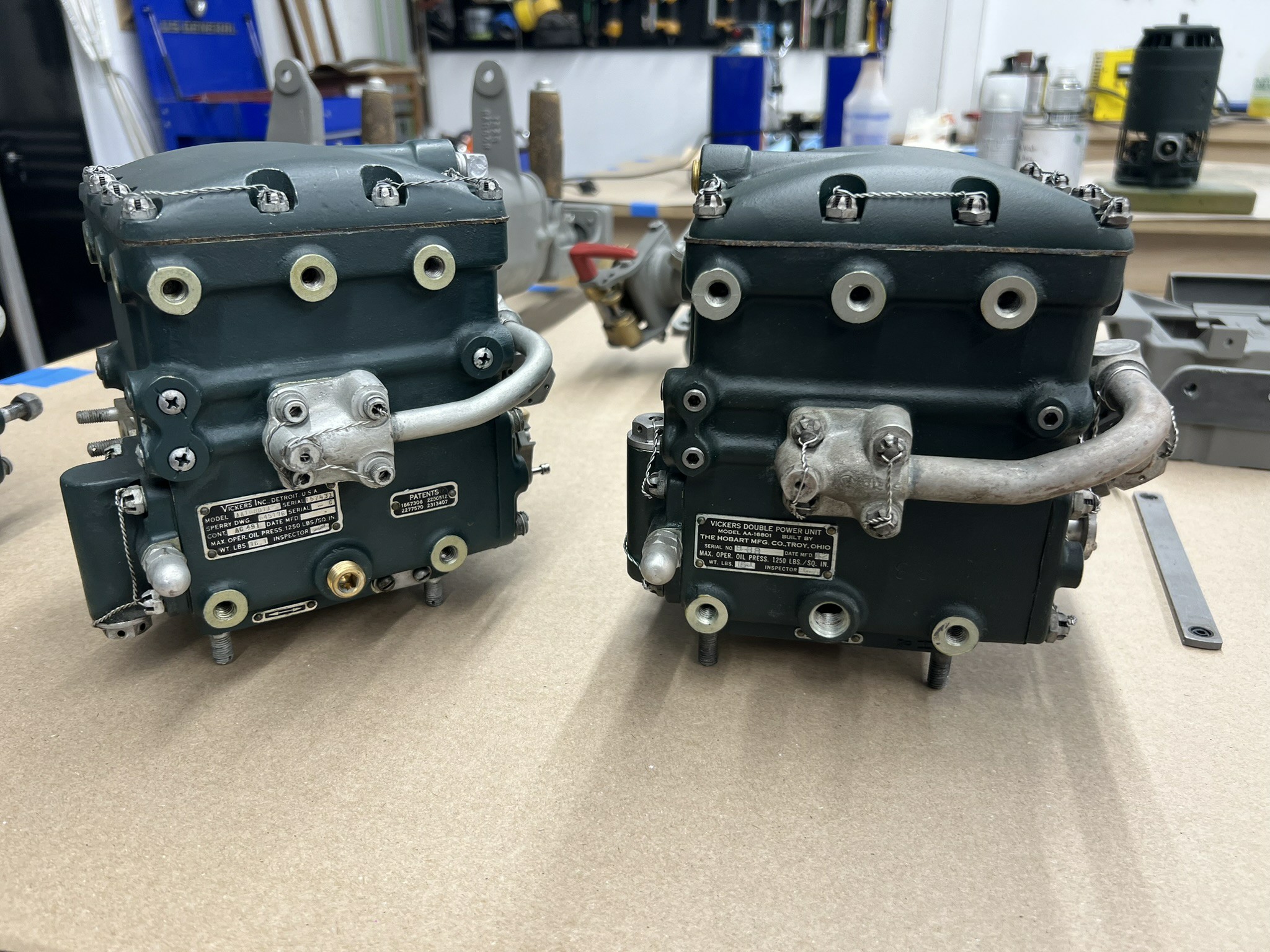
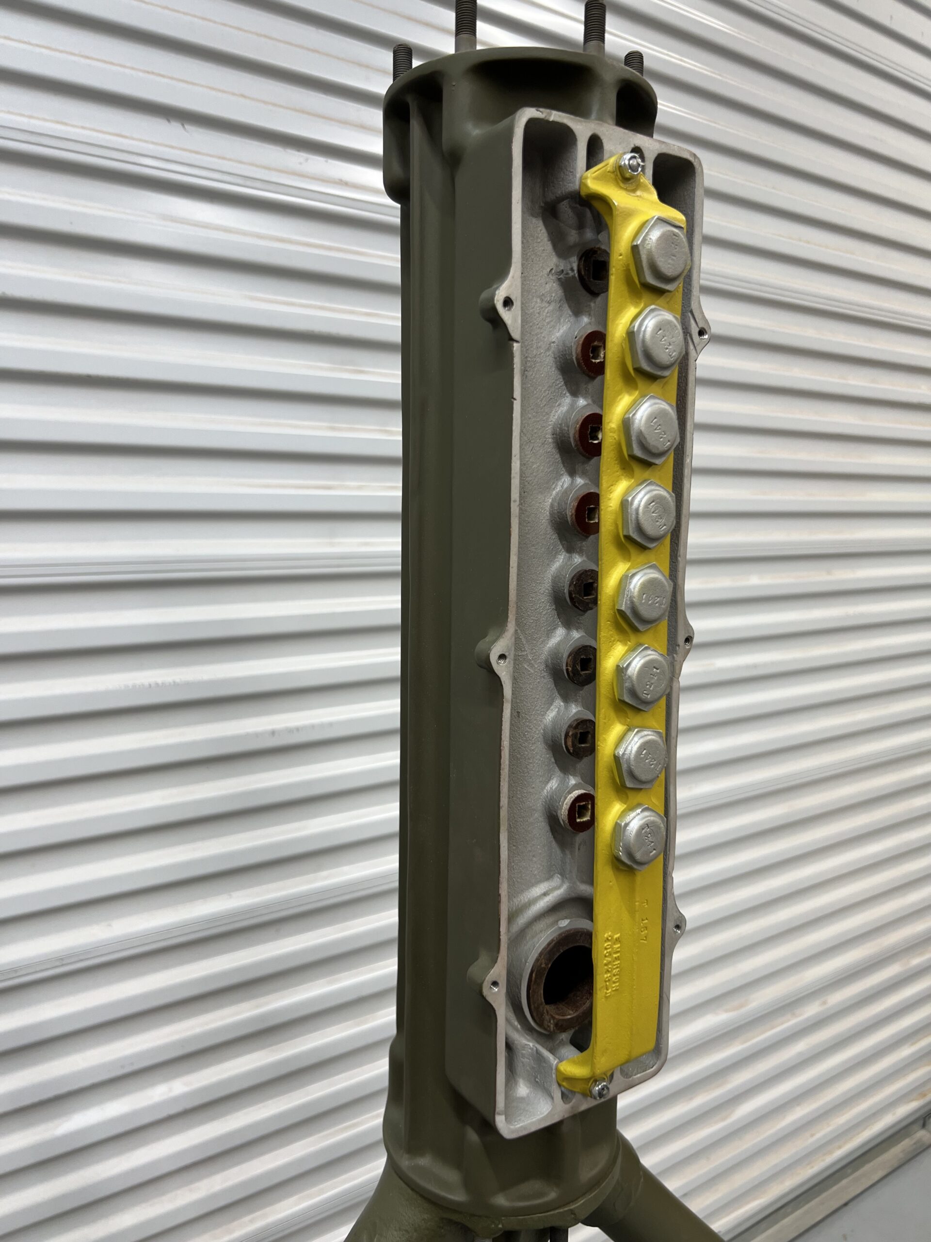
There are some small differences between the Vickers and Hobart-made transmissions, one of which is the use of socket head screws on the corners rather than Phillips.
Of course, one could also just look at the dataplate…
If you happen to have a Hobart turret transmission and are willing to help the project, please let us know!
Photo taken 12 May 2026.
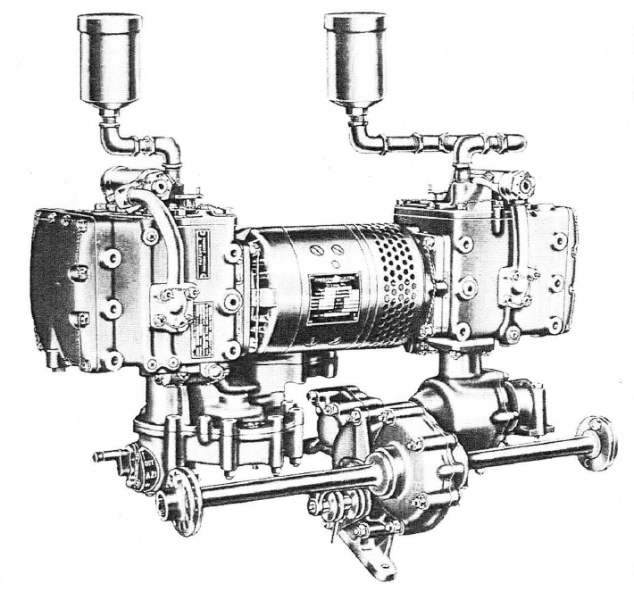
Manual illustration of the A-1 Upper Turret’s power and drive assemblies. The Double Power Unit, with its dog bone shape, can be easily seen here.
Vastly more complex than its ball turret equivalent, the upper turret’s drives consist of a large azimuth gear (the large piece at the bottom, seemingly on its side) and a pair of elevation gears. The elevation gears are not illustrated, but were located on either side of the large pole held by the vertical drive in the center.
Unlike the ball, the A-1’s gears changed a great deal between variants, making the task of acquiring these pieces far more difficult and expensive.
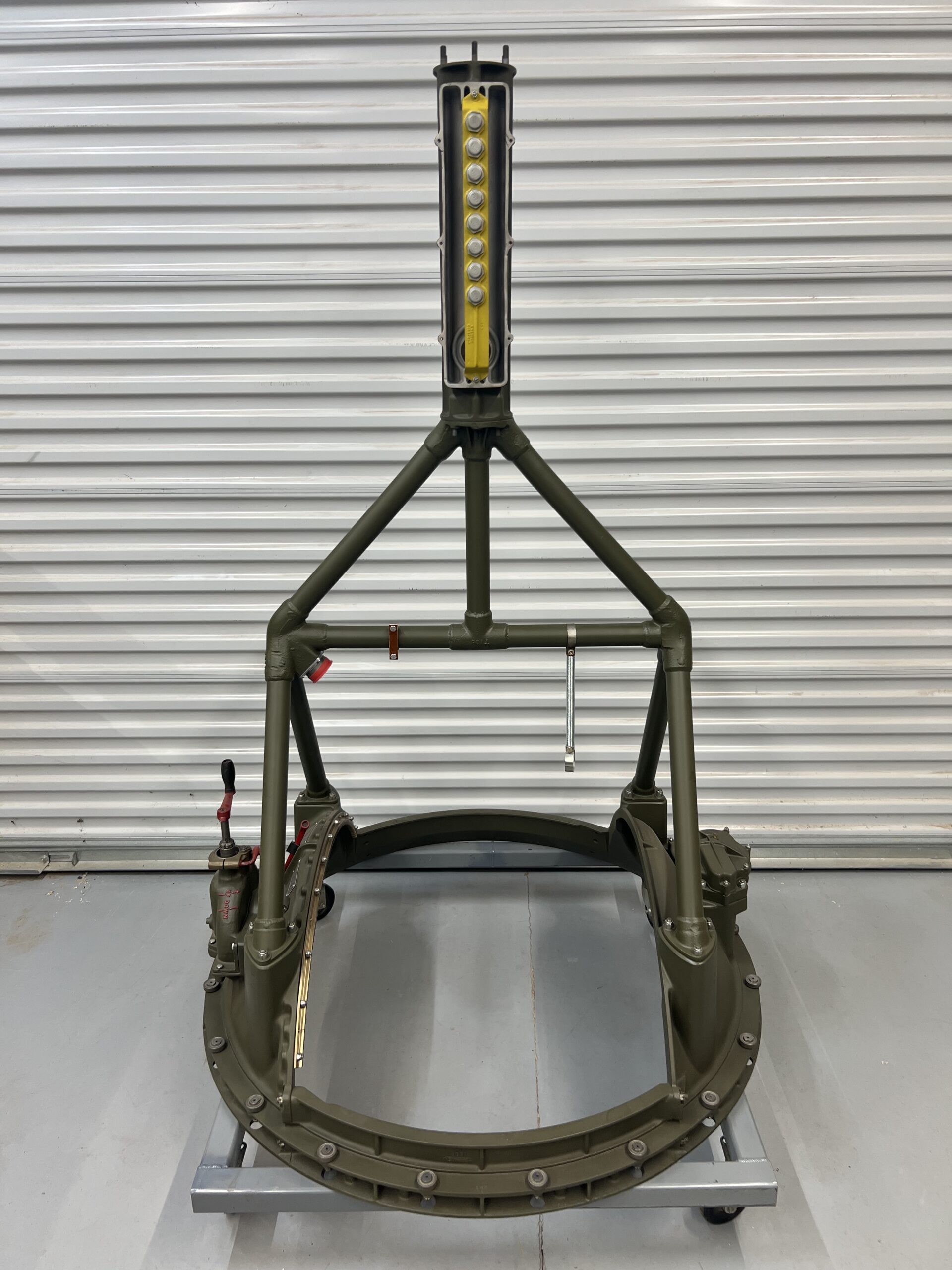
The restored trunnion and hanger assembly for Lucky Thirteen‘s A-2 Ball Turret, with the cover removed from the brush housing so that we can begin wiring.
Note the addition of the turret’s Power Socket (with a red dust cover attached), Gunsight Spare Parts Box Bracket, and Conduit Support Spring.
Photo taken 6 April 2026.
The brush assembly with the cover in place.
Photo taken 26 February 2026.
Our brush assembly comes from the UK, originating from a midair collision which occurred over RAF Great Ashfield on 26 September 1943 – just 20 days after Lucky Thirteen was shot down.
Power for the turret entered through a cast guard which was ripped away in the crash. This guard was connected to a phenolic cylinder wrapped in copper bands, which remained stationary attached to the turret’s ceiling connector. A series of copper bars were held tight against these copper bands, feeding power down to the main power socket on the upper corner of the hanger frame.
These bars were all either badly bent or broken entirely from the collision. And, while some of the phenolic guards which helped hold them in place were good, several needed to be replaced.
On the A-2, these bars connected, from the top down: main power, microphone 1 and 2, headset 1 and 2, spare 1 and 2, and ground.
Photo taken 13 April 2026.
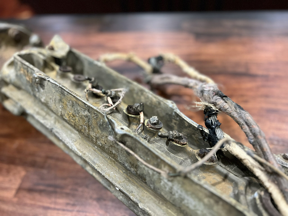
The brush housing as it appeared upon arrival.
Dorsal Queen (42-30264) and Raunchy Wolf (42-3290) of the 385BG were in a holding pattern over the field, having returned from a strike, when Raunchy Wolf collided with Dorsal Queen. The official report speculates that a frosted windshield obscured the pilots’ vision. Raunchy Wolf lost her left wing and Dorsal Queen her tail, both spiraling out of control. The only survivor was SSGT John J. Adams, tail gunner on Dorsal Queen.
We are not aware as to which of the two bombers this piece came from.
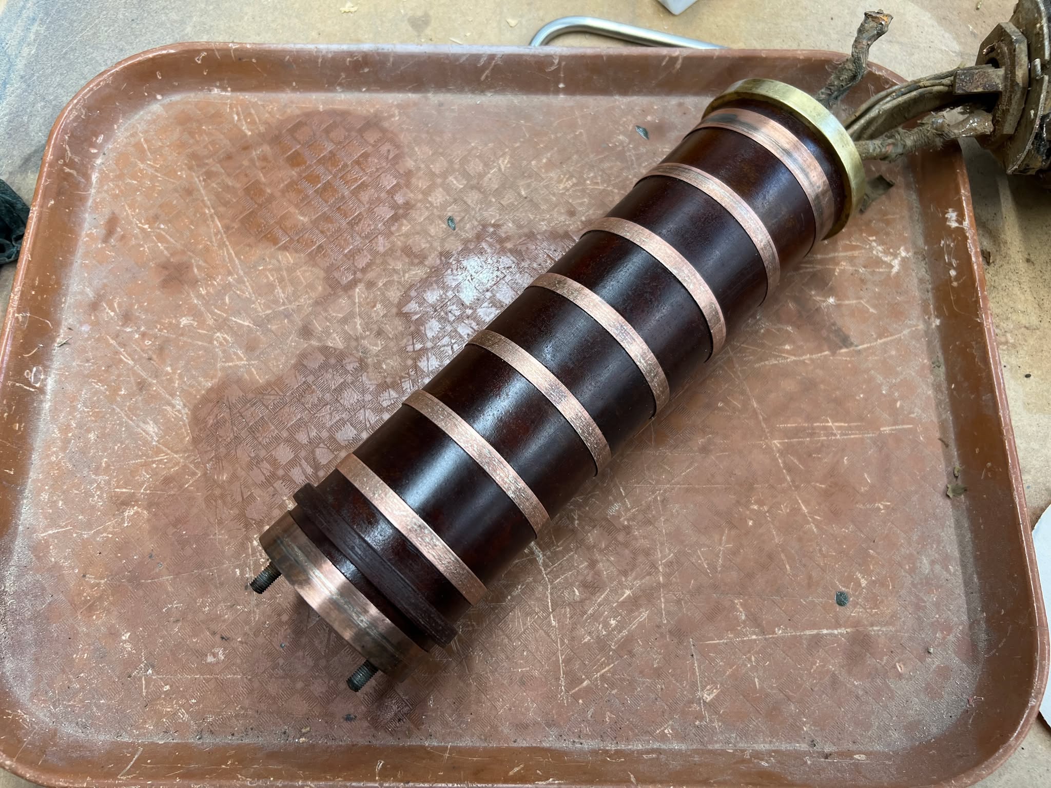
The brush cylinder is removed from its housing for cleaning.
Photo taken 11 November 2025.
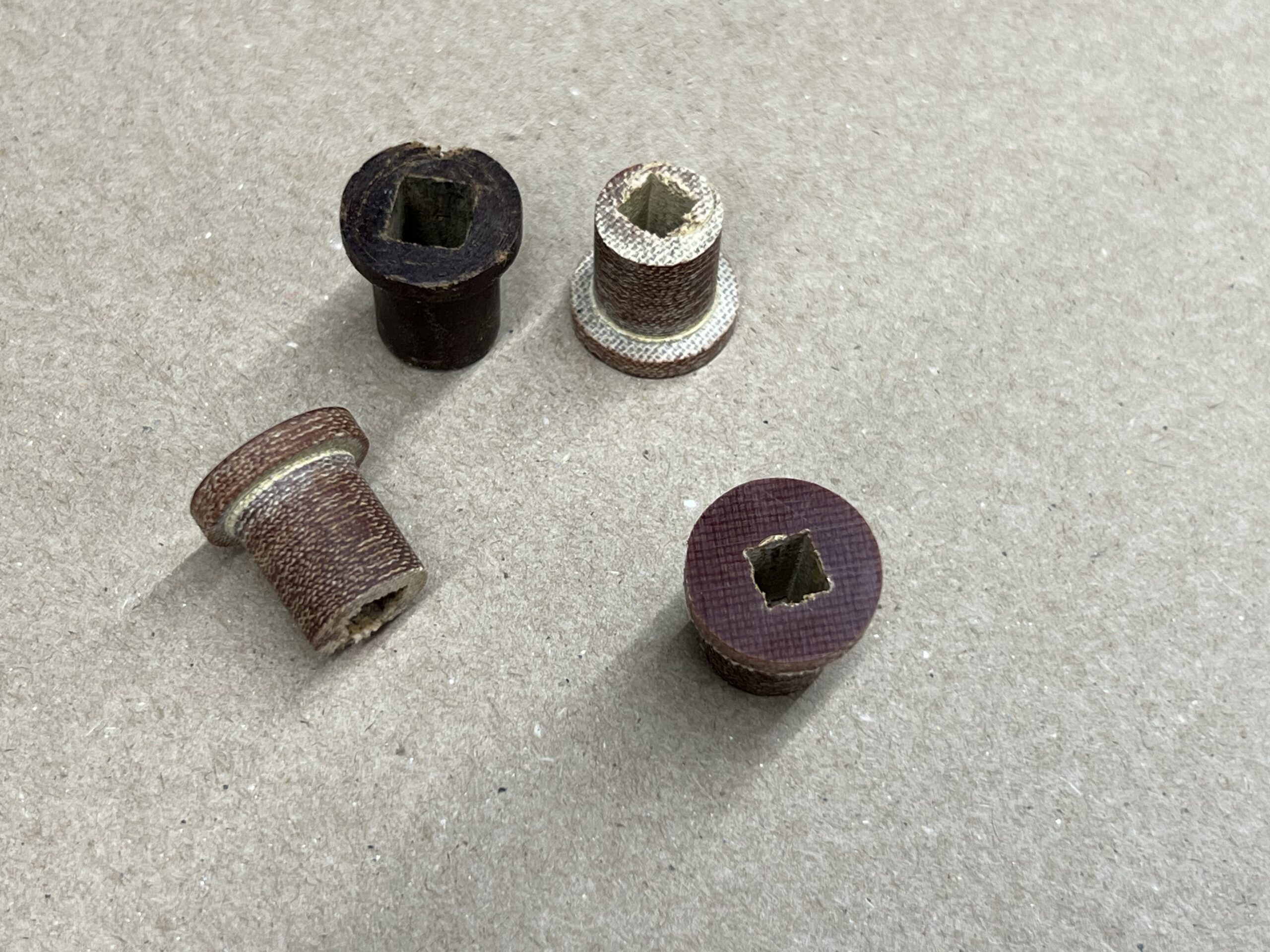
Replacements for the broken brush bar guides are carved out of phenolic.
The darker one at top is an original. The ground and main power bars were slightly larger than the others. The dark plug you see here is the turret’s main power bar guide.
Photo taken 3 April 2026.
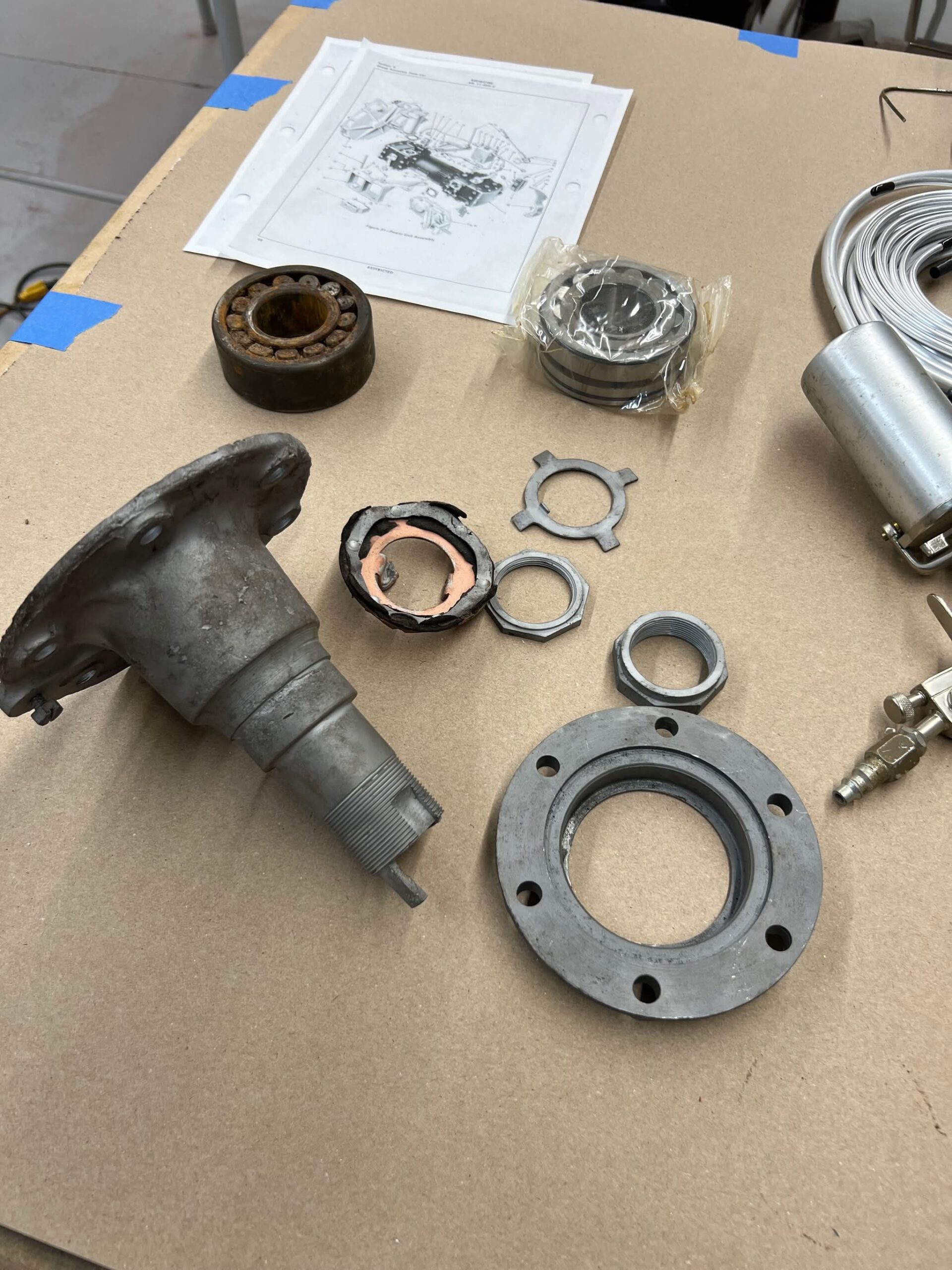
The turret’s ceiling connector is disassembled.
The main bearing, on which the entire turret rotates, is at the top. Its replacement is still wrapped in cellophane.
The copper piece is what the turret’s two ground wires connect to. A small piece of aluminum trim holds a piece of leather up against it. This copper piece is broken and will need to be replaced.
The bearing is pressed onto the ceiling mount, then fitted into the brush housing. Two prongs on the ceiling mount (one of which is broken) hold the brush cylinder stationary. The piece on the right caps off the cylinder, with a Garlock Klozure protecting the bearing. We are working to replace the V seal now.
Photo taken 11 April 2026.
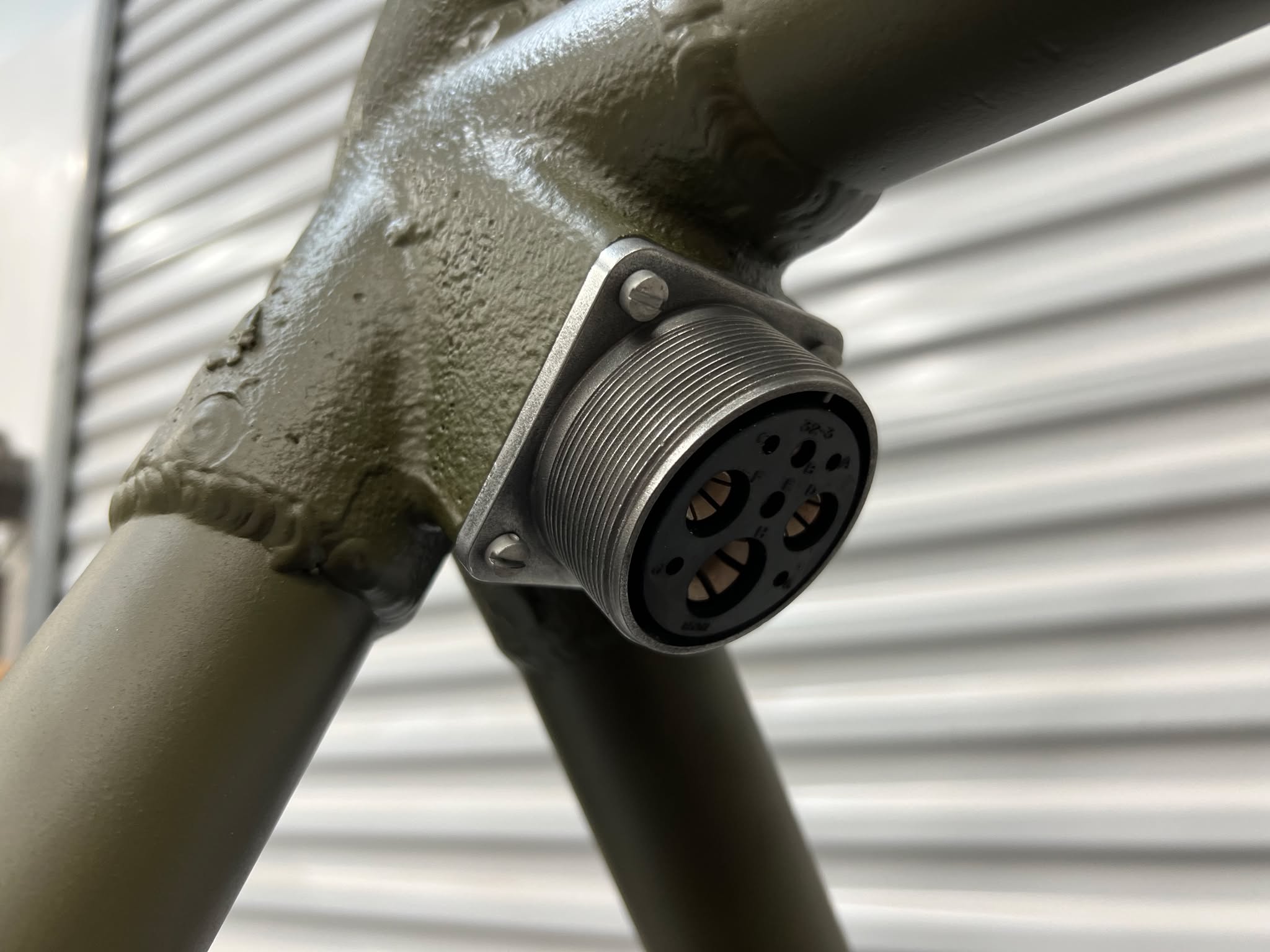
Military electrical connectors changed little since the wartime Army-Navy standard. A simple swap in prefix and the old designations usually still apply. Granted, there are always issues: modern connectors are often powder coated bright colors, and rather than affix the inserts with lock rings, modern versions are sealed in place to prevent repair. Still, the greatest annoyance is when it comes to nonstandard connector inserts.
The Sperry ball turret’s power connectors were of the 32-3 variety, which is to say each connector had one size 0, two size 4, two size 12, and four size 16 contacts. Today, only the 3102 socket shown here can be purchased with this arrangement. This means that the connectors for both the external and internal conduit lines will have to be sourced from original wreckage. Between pieces recovered from “K-King” (44-6139, 351BG) and Fred the Turret Guy’s collection, we may yet be able to pull this feat off.
This particular connector is affixed to the ball turret’s hanger assembly. The wires run up inside, terminating on a series of copper rods inside the upper housing. Said connector was ordered in December 2024 and, being made in China (as virtually all electrical connectors are anymore) did not arrive until the end of May.
We are glad it is finally here.
Photo taken 1 April 2026.
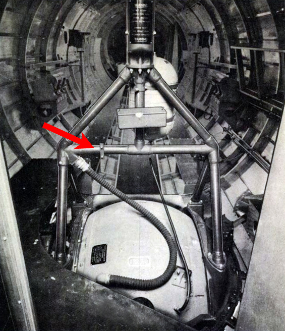
When we first acquired the A-2 ball turret’s trunnion and hanger assembly, a single strap remained clamped to the frame. This was almost certainly the upper strap for the conduit support spring. So, with the hanger now restored, we went ahead and replaced the missing spring and lower strap.
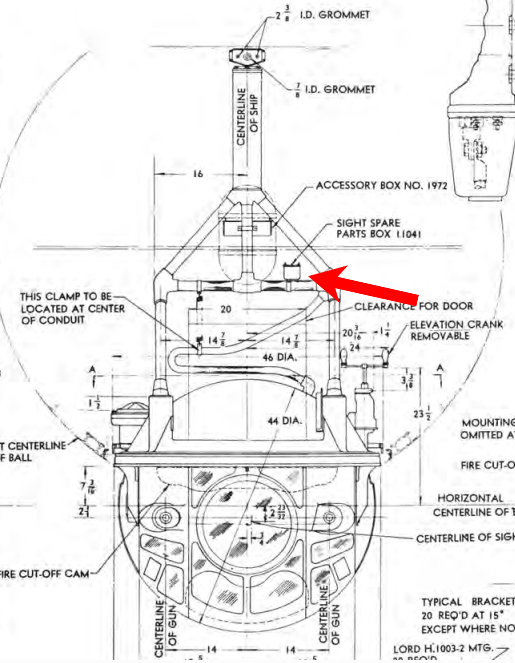
This left two more bits to attach to the hanger assembly: the Accessory Box and the Oxygen Tank Support Straps. In the midst of reviewing these pieces, volunteer Howard Lawson found something interesting. The Parts Manual listing for the Accessory Box listed a strap that was not actually meant for the box. Reviewing the manual’s dimensional drawing, he found what it was for: the turret had a provision for a second accessory box, this time for the gunsight.
Going over old photos, we found occasional examples of turrets with this strap installed – but none with the box itself.
We believe that the Gunsight Spare Parts Box was something issued alongside the turret’s Type K-4 Gunsight. The turret’s Accessory Box does not contain any equipment specific to the gunsight, and we have found examples of other gunsights that came with kits containing spare bulbs and glass plates. Considering that the nearby Spare Lamps Box by the radio compartment (provided by Boeing) would also have spare bulbs, this may explain why we cannot find any examples of this box.
If anyone has an original, or a photo of this box, please do let us know – we’d love to see!
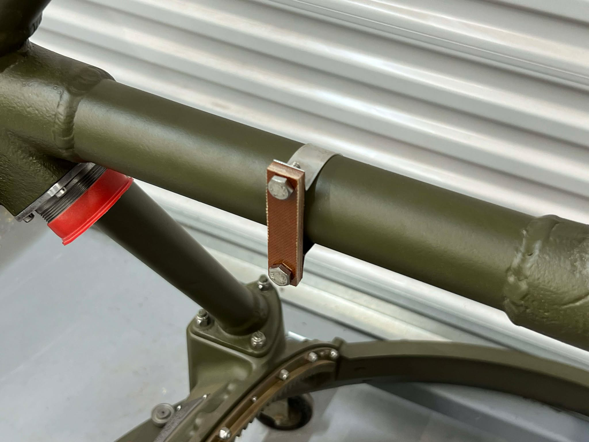
In the interest of completeness, we recreated the strap and its block to match the various wartime photos we found.
Photo taken 4 April 2026.
February we put out an appeal on Facebook for help acquiring the B-17F’s strike camera mount – and boy did people come through!
Now it is here.
To recap:
The Boeing B-17 carried its strike camera in a pit beneath the radio compartment floor. On a given operation, each bomb group would assign a handful of aircraft strike cameras. The models and positions varied. Lucky Thirteen, for example, carried a strike camera on all but one of her seven combat missions: three times a Kodak K-24, twice a Fairchild K-17, and once a Graflex K-21. Because she carried a K-17 on her final mission, this one was our ultimate restoration goal.
While not the war’s most popular camera, the Fairchild K-17 was the dominant type for high altitude operations. Some 1,300 were produced during the war, costing 2,324 USD each (that’s 38,763 adjusted for inflation). The K-17 was augmented by a Type A-5 film magazine shooting on 9.5″ wide film, and could be equipped with either a 6, 12, and 24″ lens. Depending on the lens, the K-17 could weigh up to 75 pounds. Our K-17 was donated to the project by Max Pearsall, who is currently serving in the US Air Force, back in October 2021. Thanks Max!
As with radio equipment, camera mounts are often harder to find than the cameras themselves. It is the very fact that these pieces are so innocuous that led them to being overlooked at war’s end, when ‘important’ pieces were removed at the scrapyards. The fact that we now have the correct mount for the K-17 means that we have every piece of the strike camera setup on Lucky Thirteen.
In fact, we can now announce that the Parts Drive for the aircraft’s Camera Equipment is officially closed.
There are still some minor tasks ahead, of course. The camera is missing a pair of its electrical plugs, which will have to be replaced. Similarly, we still need to track down the cables to connect the tail position’s gun camera.
Little details add up. And when we made our appeal, we received an unexpected donation of another camera component: the mounting bracket for the camera pit intervalometer. This piece comes to us from the RAF Grafton Underwood Memories Facebook page, meaning it is an actual combat veteran, almost certainly from the 384BG – the unit with which Lucky Thirteen served. This piece is a treasure for us. Thank you so much!
The intervalometer worked akin to a kitchen timer, setting the interval between photos taken by the camera. This particular bracket was kept underneath the photographer’s seat (usually the radio operator doubled as the photographer). Riveted to the bracket was a steel wedge, which interlocked with a pair of steel wedges on the back of the intervalometer, similar to a carpenter’s French cleat. A second steel wedge was also installed in the nose compartment, along with a second camera electrical panel, allowing for the bombardier to control the camera if necessary. The steel wedge had rotted away from our bracket, requiring replacement.
I will admit to not being terribly knowledgeable about cameras, and if there are any camera experts local to the Carolinas interested in volunteering, by all means let us know. We know for a fact that it is still possible to obtain film for these cameras. So, it would be fantastic to actually see it working.
But as it stands, we are ecstatic over these new arrivals. While there are still some minor tasks ahead before calling them complete, the fact that all the major components are here is incredible. We are already planning to build a display to showcase these pieces together.
To all of you who made this possible, thank you!
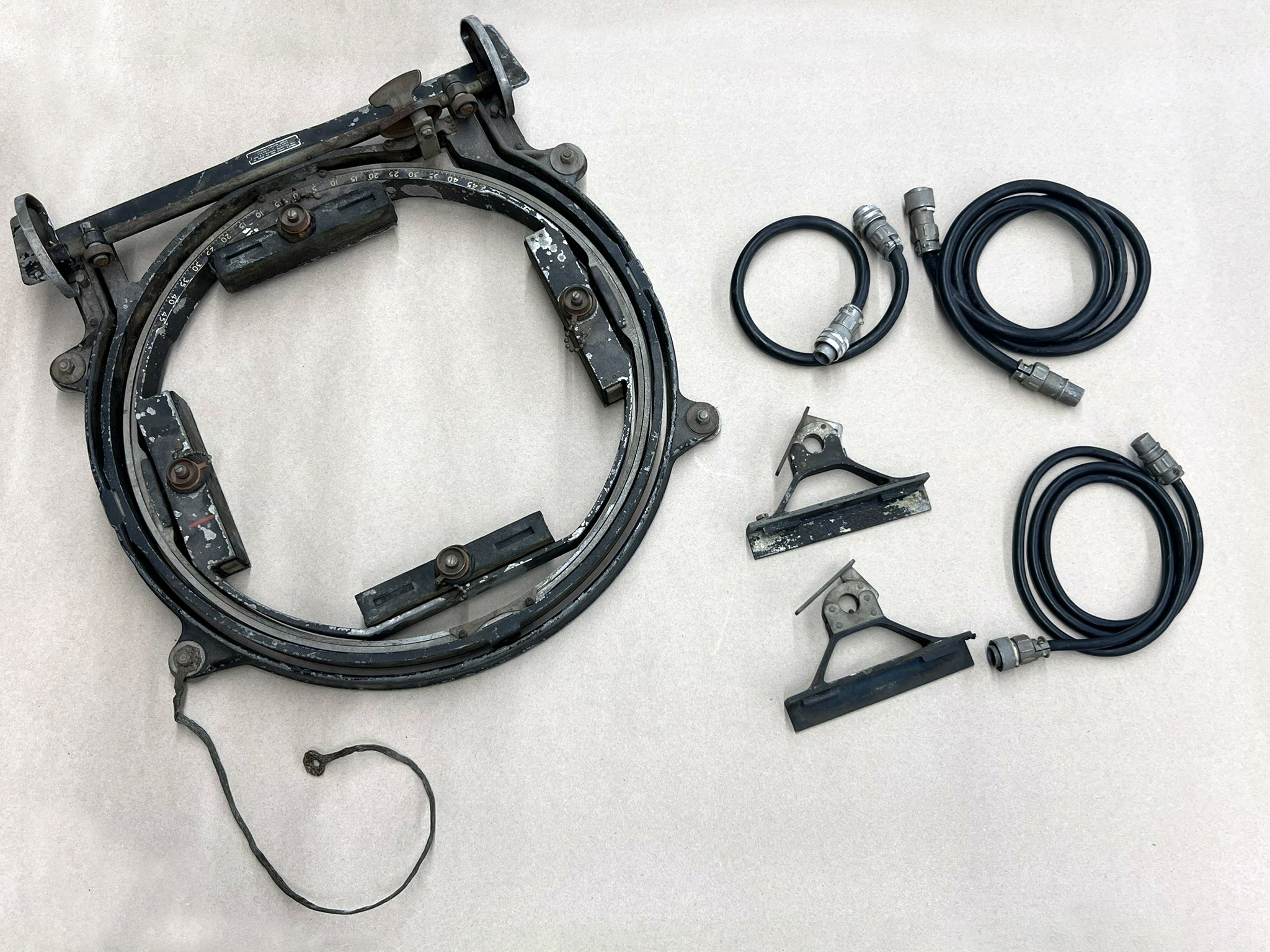
The newly arrived A-11 Camera Mount along with the appropriate cables for operating the Fairchild K-17 Strike Camera.
Photo taken 2 March 2026.
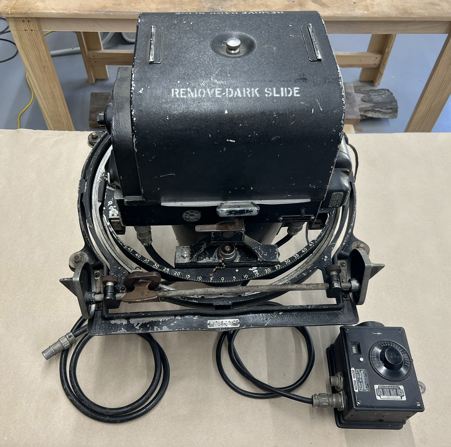
The Fairchild K-17 Strike Camera is attached to the newly arrived A-11 Camera Mount.
Photo taken 4 March 2026.
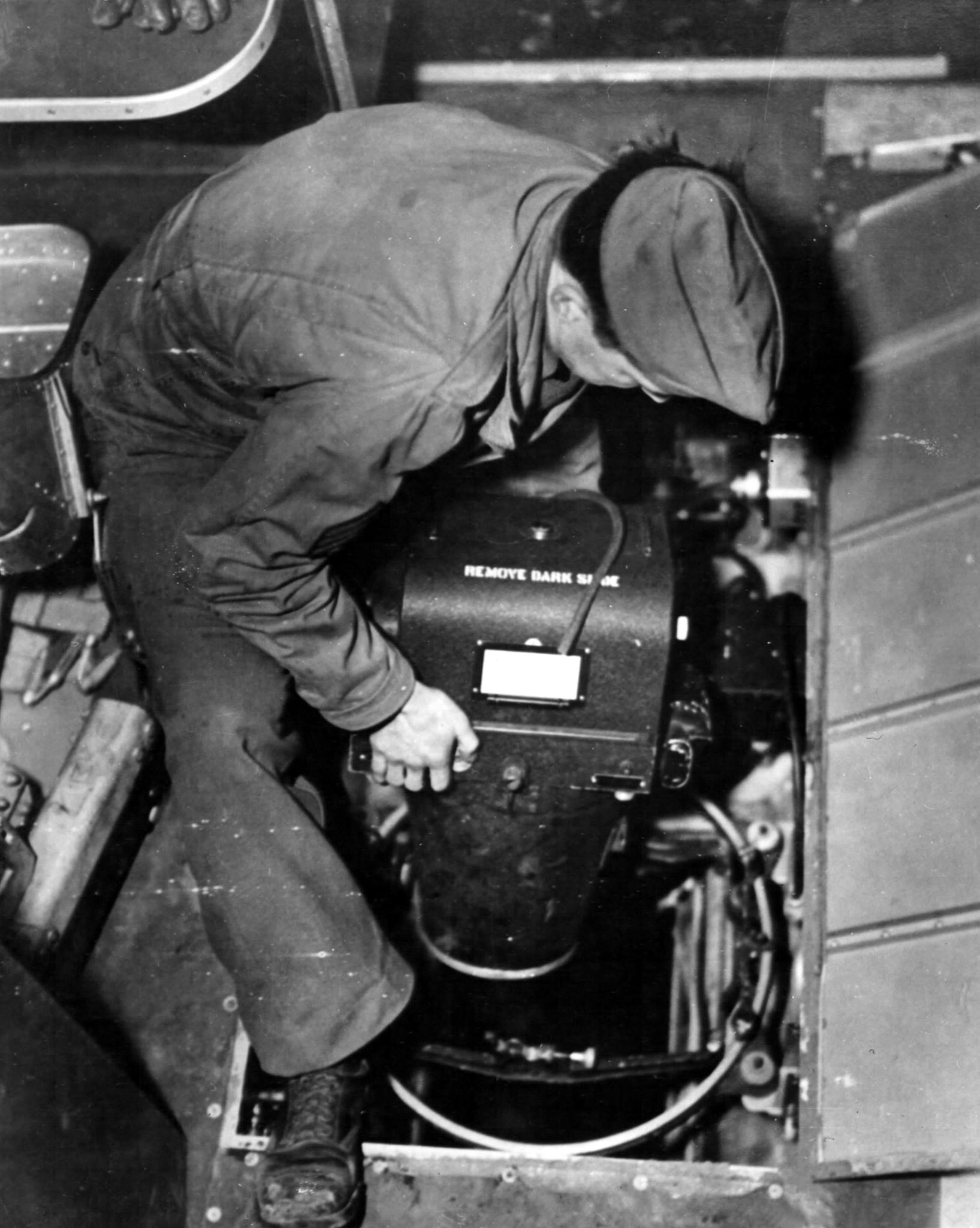
Wartime photo of a Fairchild K-17 Strike Camera and its A-11 Mount being installed aboard a Boeing B-17.
Based on the radio operator’s seat and table, this is either an E or early-F.
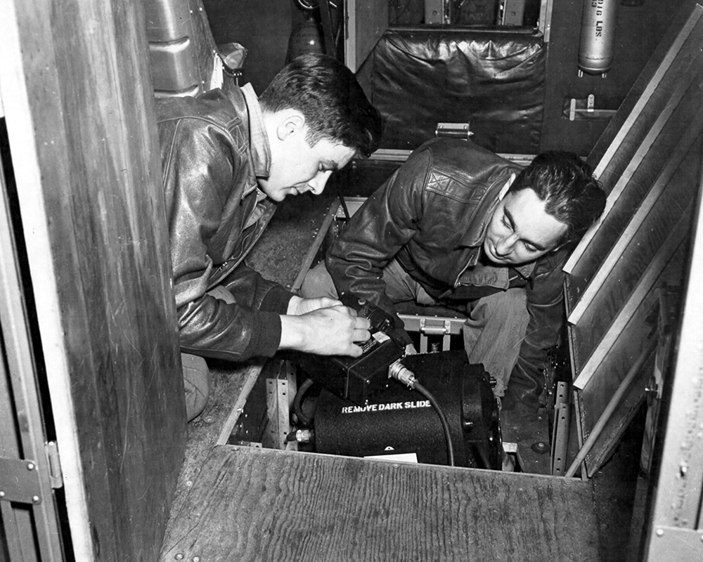
SSGTs Bill M. Lyon and John A. Feairheller install a strike camera aboard Our Gang (42-5069, 91BG).
Our Gang was lost over Schweinfurt on 17 August 1943.
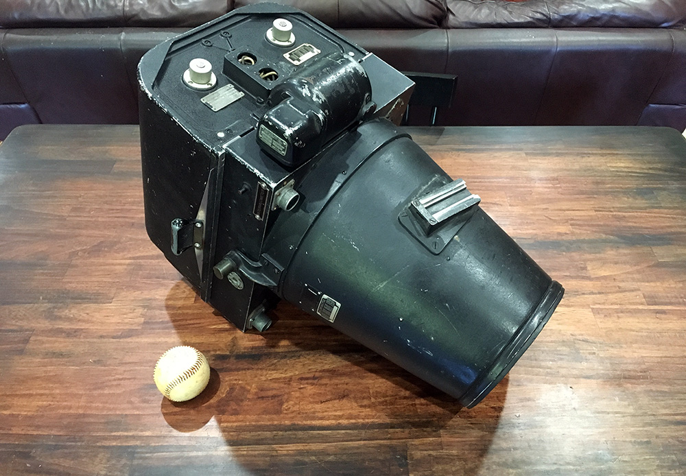
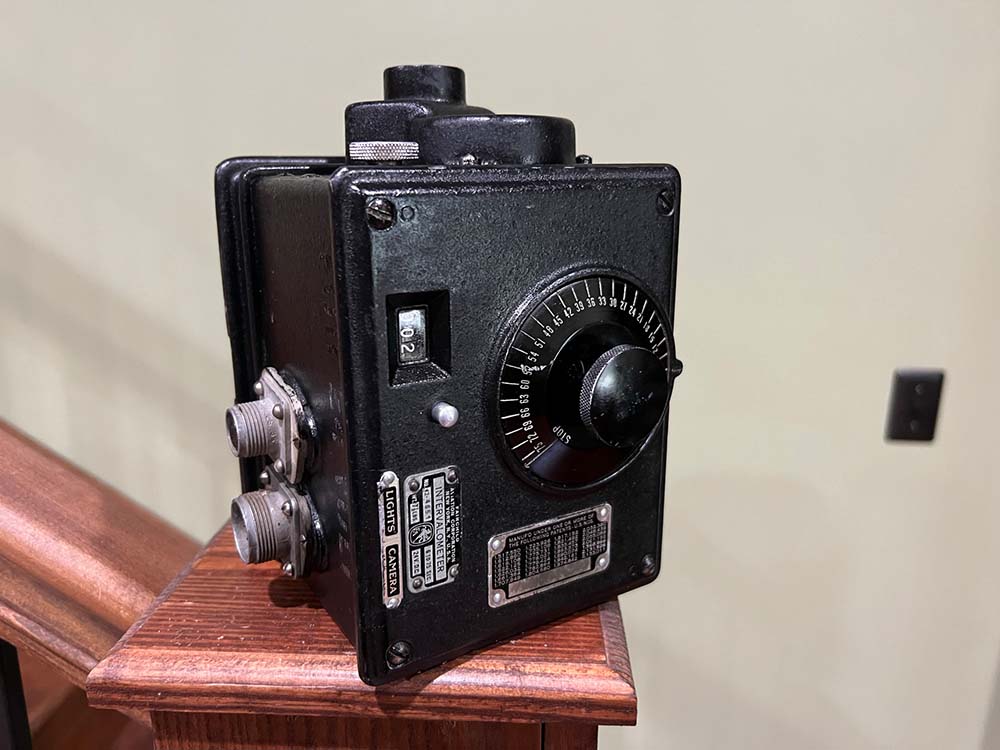
The Fairchild K-17 Strike Camera with a baseball for scale.
The missing electrical connectors are visible here.
Photo taken 18 October 2021.
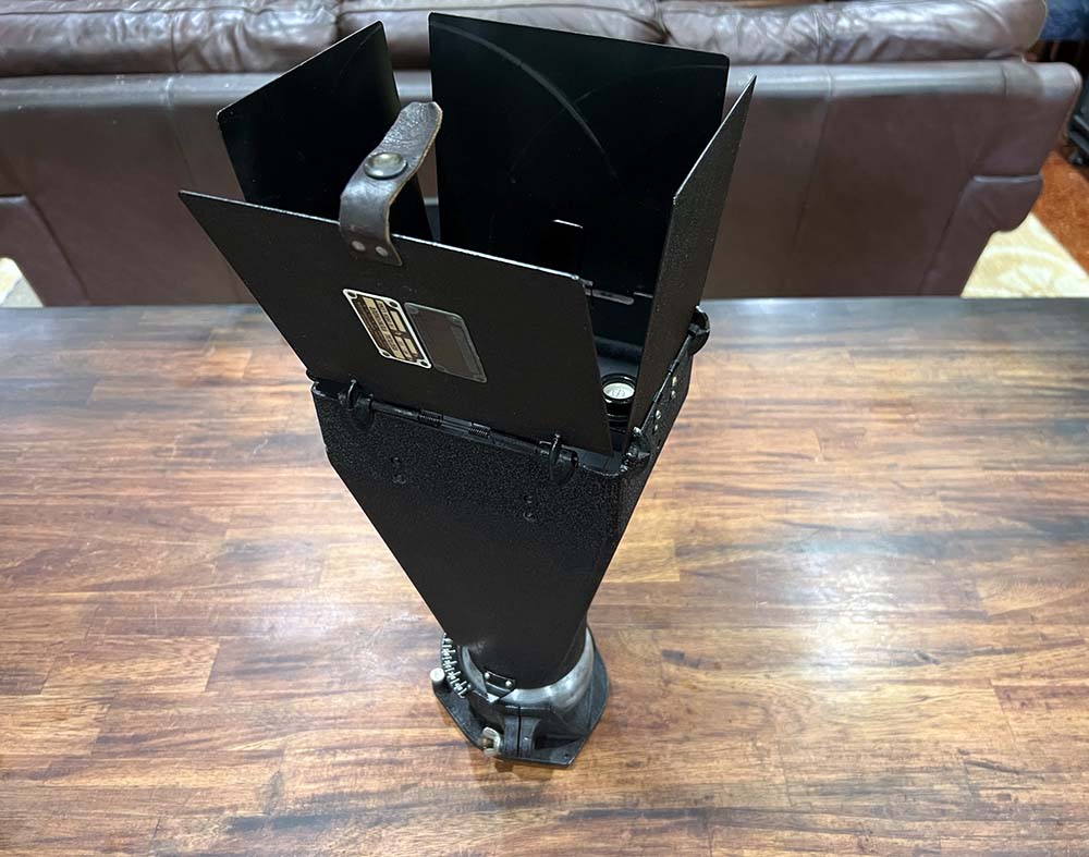
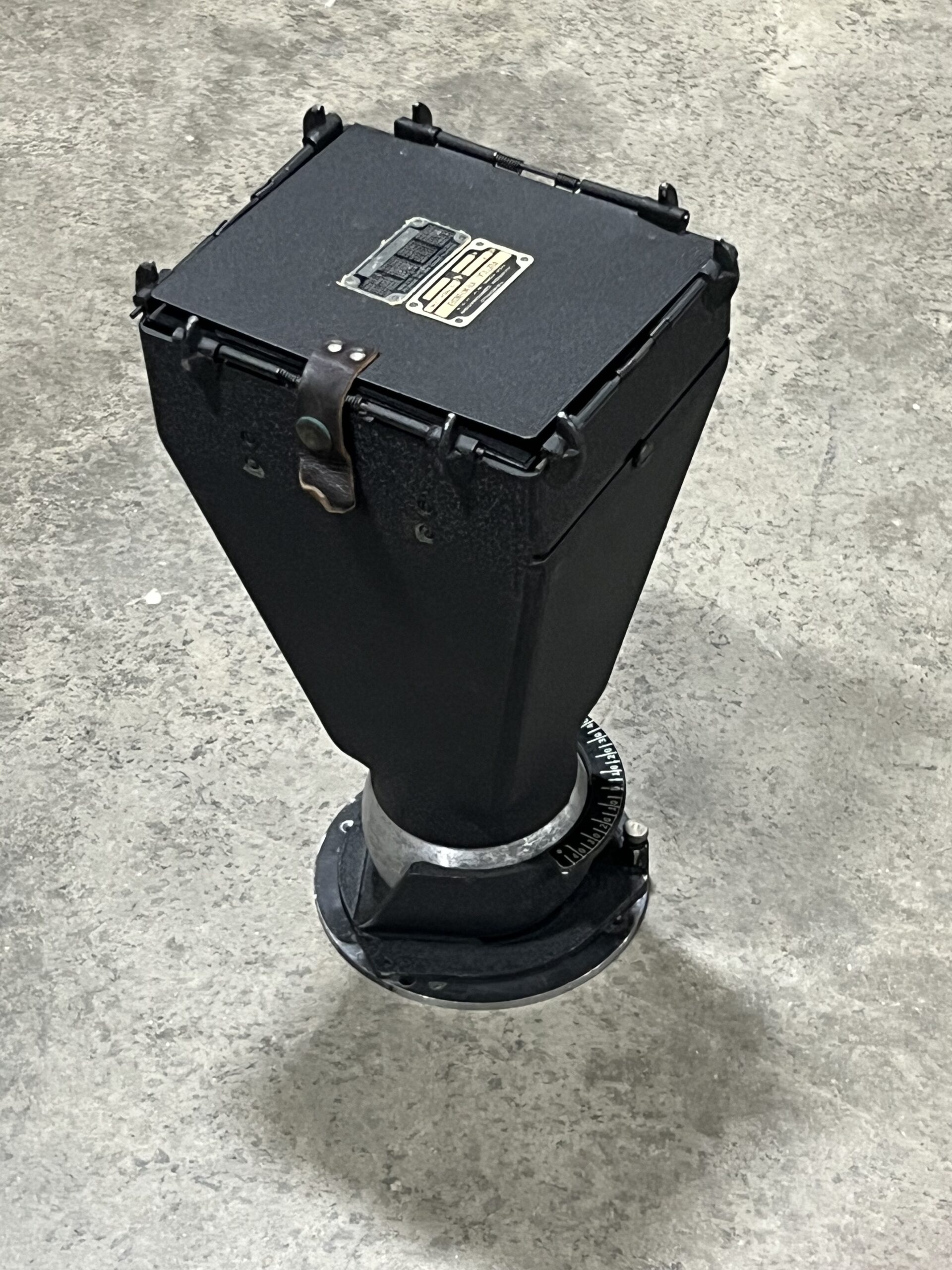
The aircraft’s A-2 Vertical View Finder, which could be used to aim the camera when not used by the bombardier.
Photo taken 11 September 2022.
The B-2 Intervalometer for Lucky Thirteen.
While there were multiple intervalometer variants, this is the type most appropriate for the summer of 1943.
Photo taken 31 August 2022.
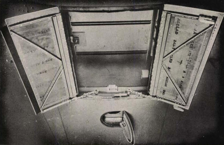
Manual image of the Boeing B-17’s strike camera hatches.
The larger hatch is for the camera and the smaller one for the vertical view finder.
Note the ALCLAD stamps on the bare aluminum.
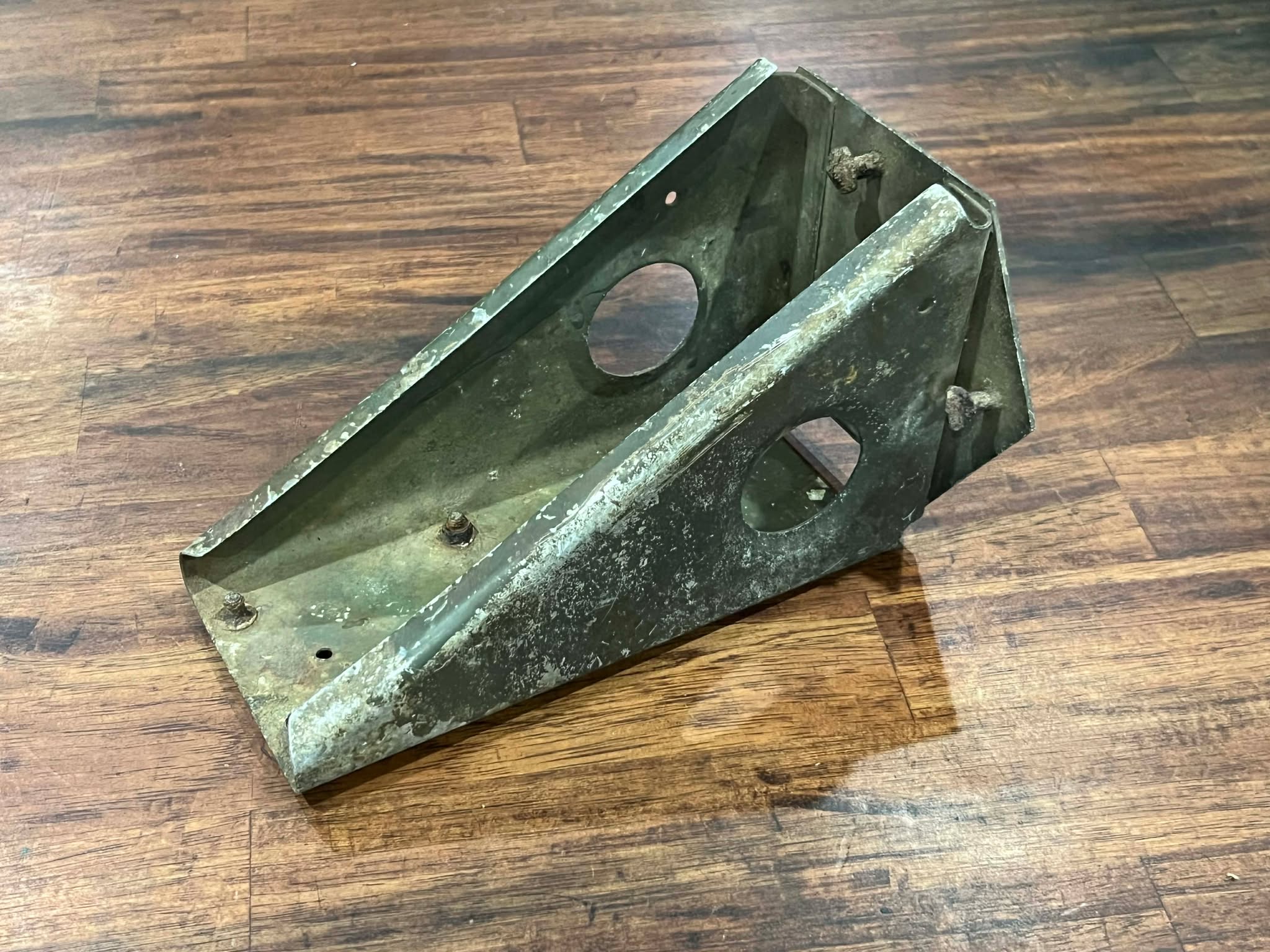
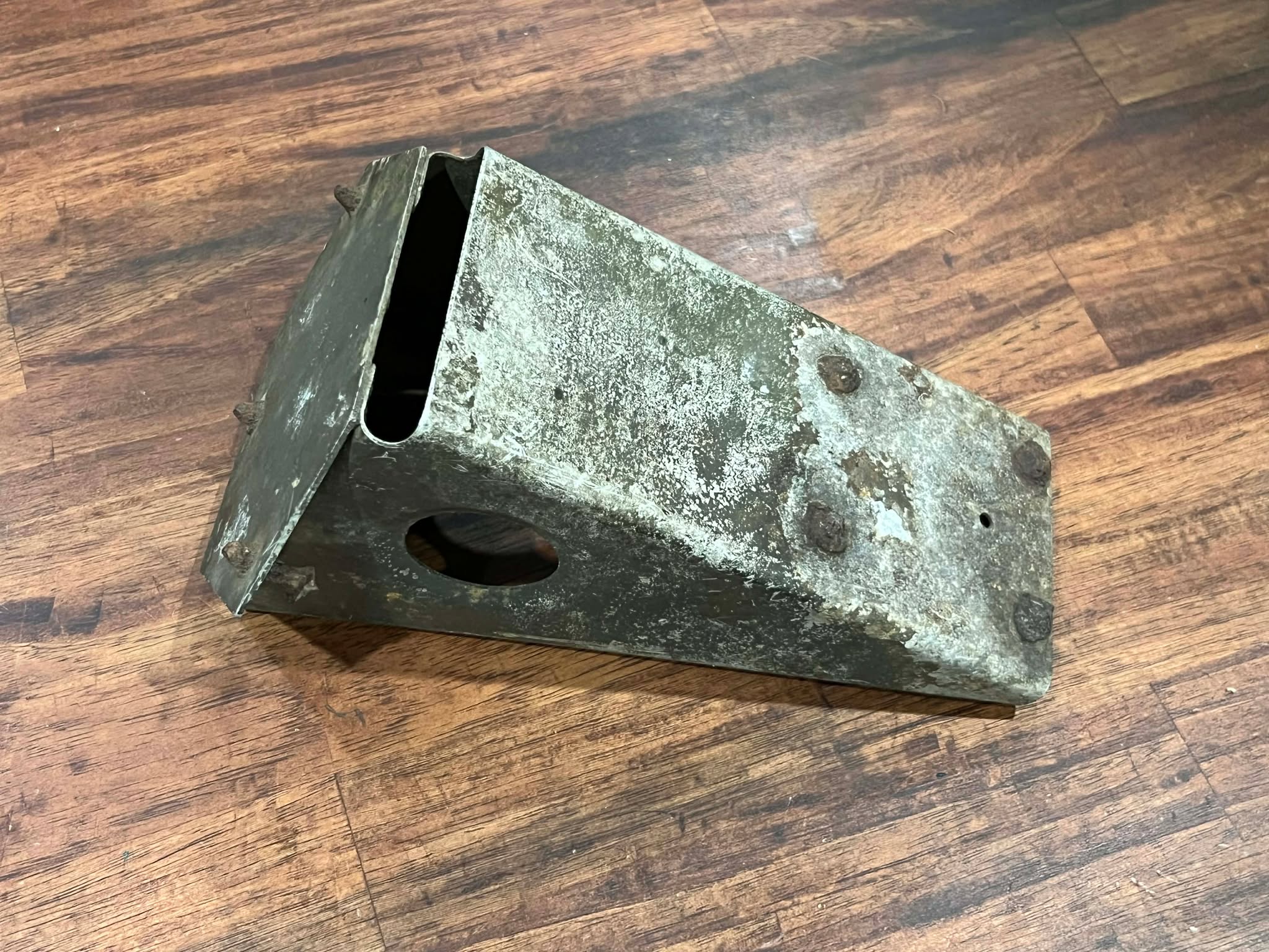
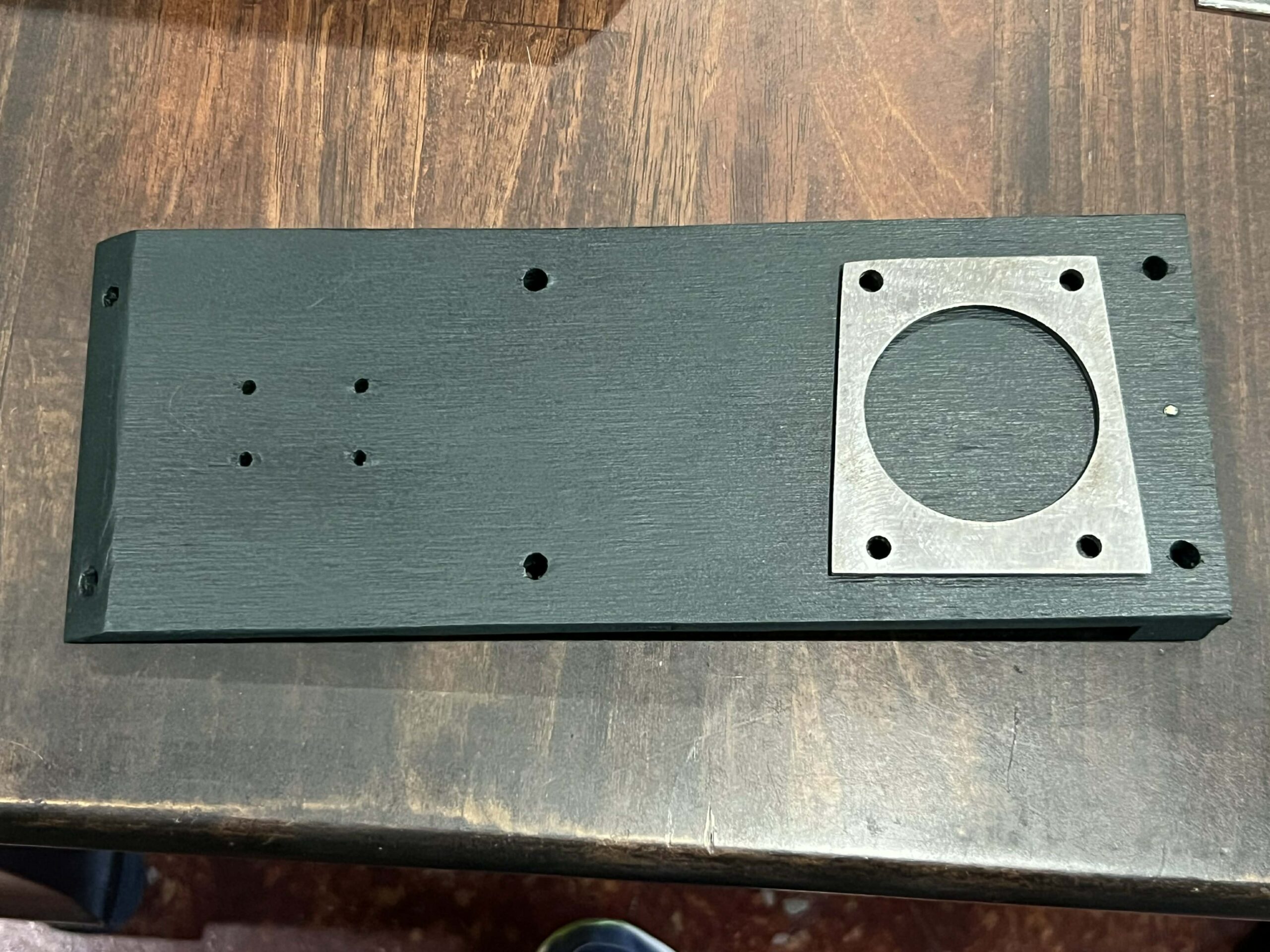
The newly arrived camera pit intervalometer mount.
Photo taken 28 February 2026.
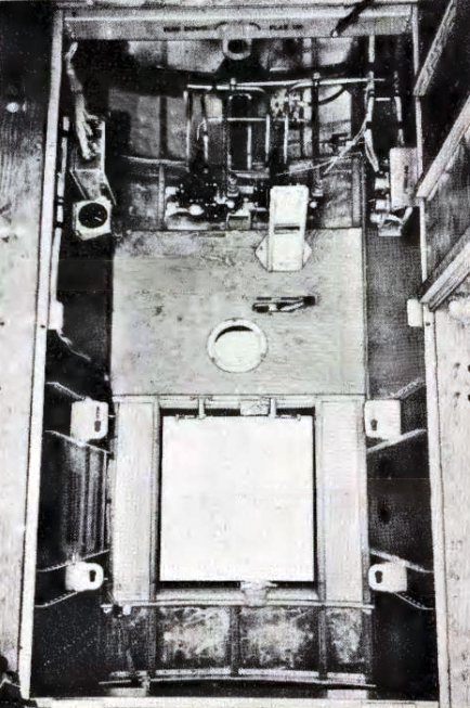
Manual image of the camera pit beneath the radio compartment floor. The seat has been removed in this picture.
The intervalometer bracket can be seen near the center, top in its stowed position. A matter of personal preference, the intervalometer could also be simply bolted to the wall.
The four tabs at the bottom are for attaching the camera mount. The circular hole is the mount for the vertical view finder.
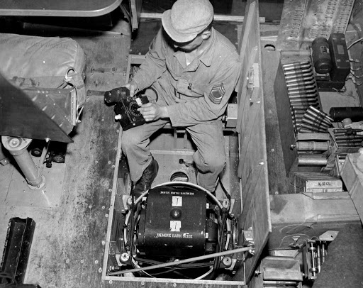
MSGT Harry B. Good of the 303BG installs a K-17 Strike Camera aboard an early-B-17F.
Several interesting pieces can be seen here, including the back of the cockpit fuse box (why it is here, who knows), several types of ammo cans, and under the radio operator’s seat, a partially obscured A-2 Walkaround Bottle (unique to aircraft with constant flow oxygen systems).
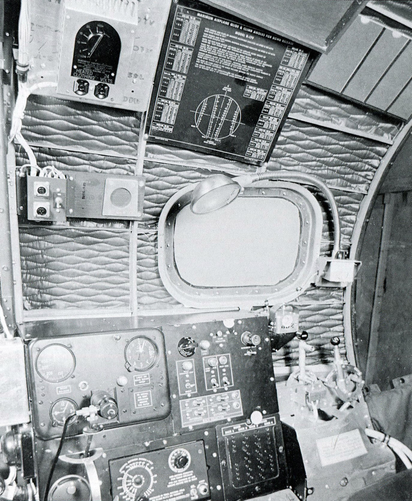
The nose of 42-30323, a late B-17F that never left the US. This is nearly identical to the setup aboard Lucky Thirteen.
The bombardier’s camera panel is the left, center. The triangular piece with a hole is the bracket for the intervalometer – should the bombardier be operating the camera.
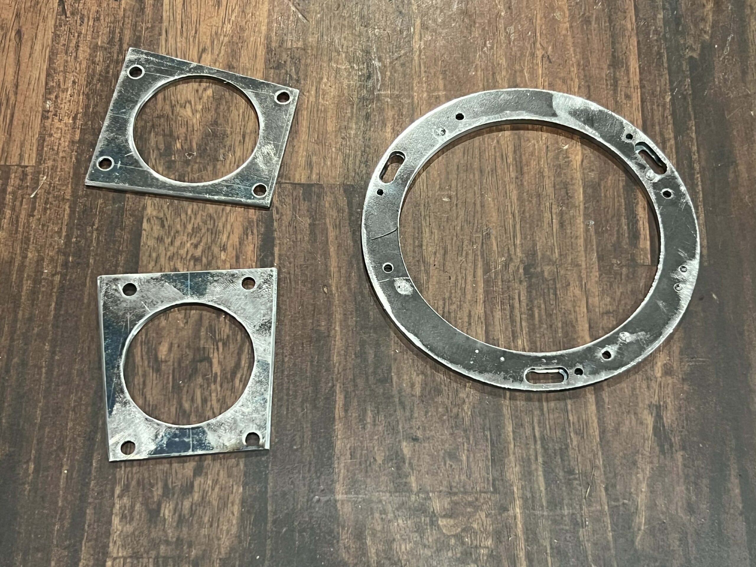
Needing the intervalometer mounting bracket, we put out a call for anyone willing to machine them. Brent VanDervort of Charlotte, North Carolina stepped forward and did an amazing job.
The circular bracket on the right was a last minute addition, which Brent was kind enough to add to his To-Do list. This is the bracket which the camera’s A-2 Vertical Viewfinder clips to when mounted to the floor.
Being steel, these pieces will eventually be cleaned and cadmium plated to match wartime spec.
Photo taken 6 March 2026.
Work already underway to recreate the missing camera electrical panels. This is for the bombardier’s panel. It photographs darker than it really is.
Photo taken 4 March 2026.
The A-2 Vertical Viewfinder is clipped to Brent’s newly-fabricated mounting bracket.
Perfect fit.
Photo taken 18 April 2026.
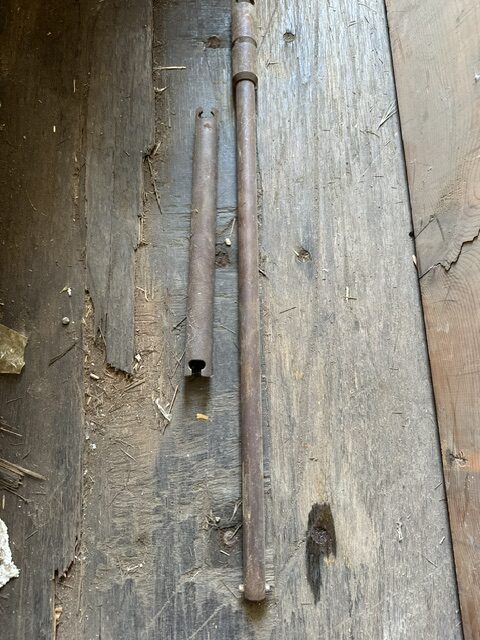
A pair of B-17 hand crank extensions from an undisclosed location. We will need to recreate these for Lucky Thirteen, assuming originals cannot be sourced.
The Hangar Thirteen Foundation needs additional volunteers, in particular peoples with machinist and metal fabrication skills. This is the sort of project one might can expect, if willing to participate.
One unique aspect of our work is that we actively encourage long-distance volunteering, meaning that you need not be local to Asheville to work on Lucky Thirteen. As long as you keep your eye on the ball, you are more than welcome to work from home.
And if you are local, you are welcome to work in the main shop, too. One way or another, just let us know…
The Hangar Thirteen Foundation is a 501c3 nonprofit charity dedicated to bringing back a B-17F representative of the bloody counter-air campaign of June 1943 through March 1944. Donations to this project are tax deductible. If you can spare a little to help this project, you can guarantee that you will see the results on Facebook and here on our website.
You can contribute through the Donate page or, to avoid a PayPal fee, you can send something via the mail to:
Gerad Allen Blume
Hangar Thirteen Foundation
442 Old Chalk Bed Road
Batesburg, SC 29006
Volunteers are also always welcome. In fact, you need not be an Asheville resident – you can work from home! Persons skilled with metal fabrication, machining, CAD modeling, metal casting, 3D scanning, and laser/waterjet cutting, are particularly helpful. Just reach out to us to get started.
Keep the show on the road!