
Regular updates were put on hold for the month of June to focus on our annual fundraiser. People can Donate at any time but every now and then it helps to hold a sort of revival.
And in this update, you can see pieces which we acquired thanks to the support of those who contributed!
The big news over this summer is that we now have blueprints for the Sperry ball turret.
Here’s the story:
After some extensive research and digging, the National Air and Space Museum, Smithsonian Institution was able to confirm with us that some drawings still exist. These were filed under Briggs, as Briggs was the original manufacturer for the turret, Sperry having only designed the ball.
Now, there are some limitations. Many drawings are missing and the Smithsonian still will not offer duplicate rolls, nor have they any digitization services. So, physical copies must be ordered and only a certain number can be ordered at a time.
That said, with our own research thus far, we have managed to extensively document the evolution of the turret. And, with our work restoring the A-2 for Lucky Thirteen, the only significant challenge before us on the ball is the shell itself. So, those are the drawings we ordered.
Since it seems unlikely that anyone with an original ball will work with us, unless something changes, we will have to cast our own. Having 3D scanned an original A-2 already, these drawings will finally fill the last information gaps to make that happen.
Unless an original becomes available…

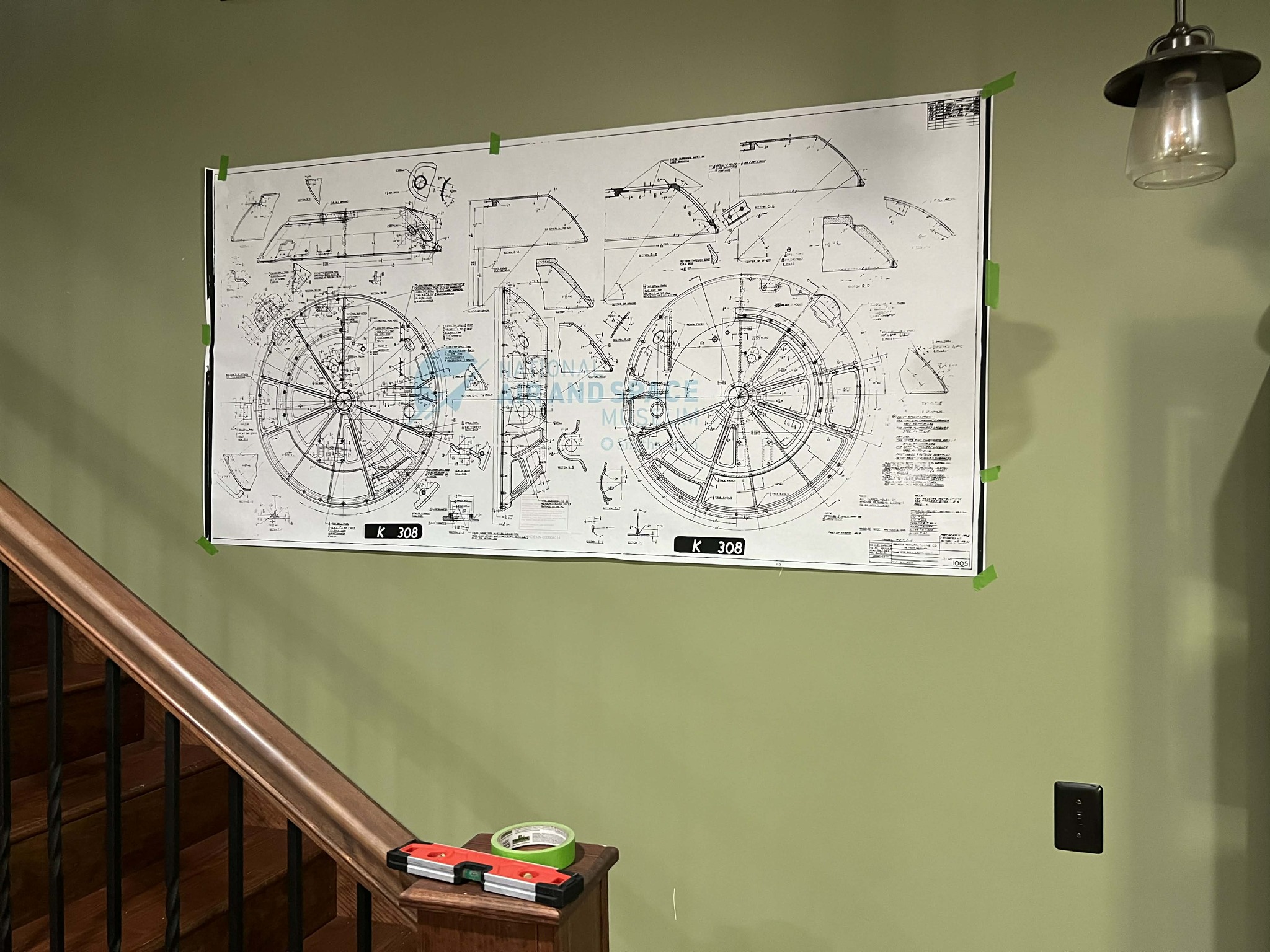
The blueprint for one of the turret’s end bell castings.
Photo taken 24 April 2026.
This is a piece we have been after for a long time – the Ball Turret Accessory Box.
All four variants of the Sperry ball turret featured an accessory box, though only the A-2 used this particular clip-on variant.
While this example is missing its lid, we are fortunate that it still has its wooden insert. Better still, it is a Briggs-made variant. (Since our ball is a Briggs, we are trying our best to have a matching-parts turret.)
The piece now restored and installed, the only bits missing are the lid and the pieces which go inside. And while it may be silly, it would be nice to try and fill out the contents of the box too.
So, anyone up for a treasure hunt?
Fred the Turret Guy was kind enough to fill out the spare fuses for the Trouble Light, Suit Heater, Gunsight, and Gunfire/Cut-off circuits. So, that leaves:
– 2x 301-30P-24-28V Mazda Bulbs
– 2x Briggs 877/Emerson 205394 Slip Ring Retainers
– 2x Briggs 871/Emerson 205407 Brush Bars (5/16)
– 2x Briggs 869/Emerson 205410 Brush Bars (1/4)
– Briggs 1903/Emerson 206268 Door Check Wire Clip
And most importantly –
– 2x 125V/120A Cartridge Fuses (Littelfuse 1402, Army Spec 94-32272)
Recent calls for machinist volunteers (alongside our regular calls for fabricators) have gotten no replies. But we do have a friend with another group whose willing to try making new brush bars for the turret, so filling out the spares would involve just making a few extra. The original bars from our housing were all damaged beyond repair in the crash.
The Slip Ring Retainers would involve finding additional examples of the octagonal pieces on the brush housing. Maybe someone has some wreckage?
But it is those 125V/120A fuses that are the real kicker – the turret cannot operate without them. The only matching fuses we have been able to locate of the same size is the ACL-120 (note that it is NOT the ACK-120). The issue is that few vendors carry the ACL-120, and the few who do, are prohibitively expensive. Maybe someone can help with that need?
One way or another, we are psyched to have Accessory Box here. We love little details.
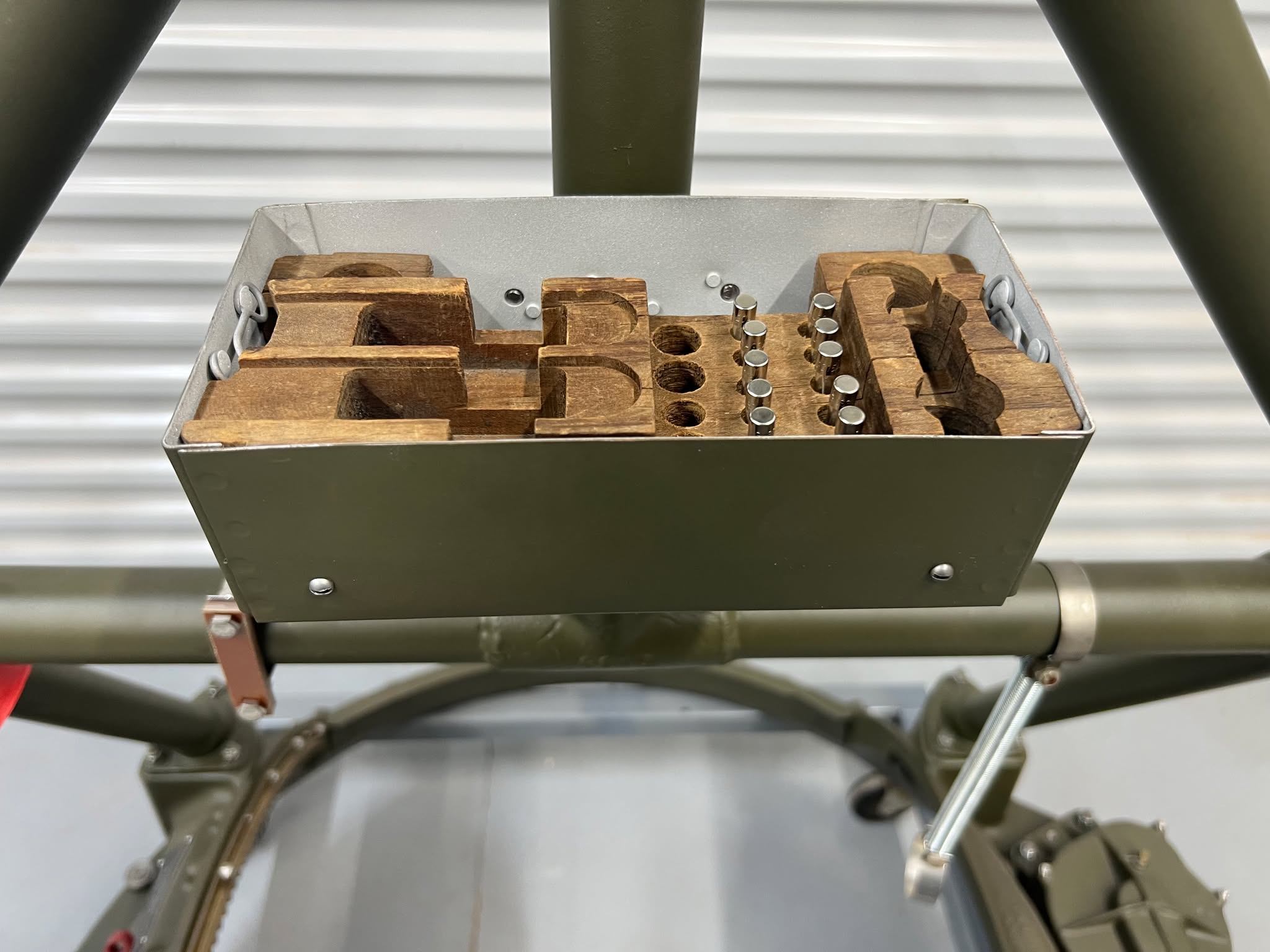
The restored Accessory Box on the turret’s hanger assembly.
Photo taken 4 May 2026.
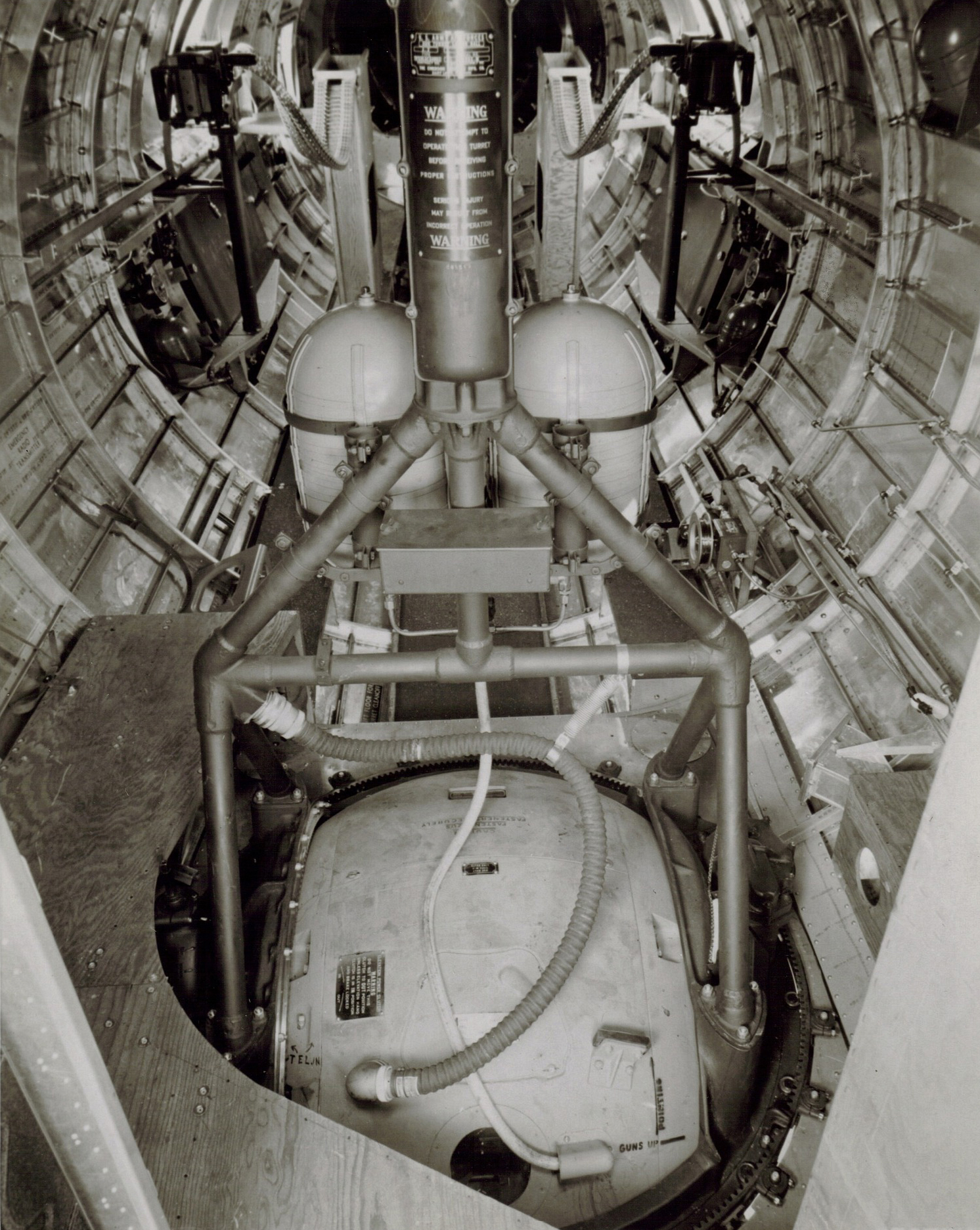
The A-2 turret aboard 42-31233 of the 303BG. Note the Accessory Box in the center. The dual oxygen tanks was common to B-17Fs in late-1943.
42-31233 was shot down on 20 December 1943 over Bremen, Germany, with eight killed and two taken prisoner.
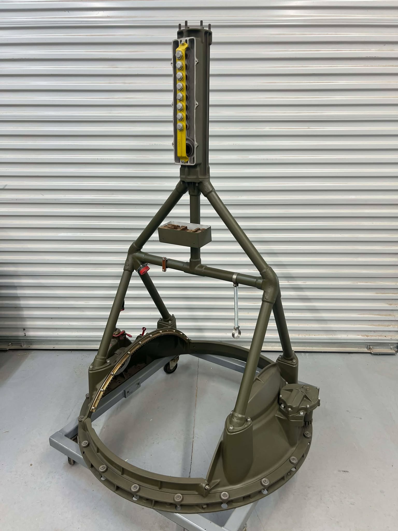
The A-2 Ball Turret hanger for Lucky Thirteen with the Accessory Box installed.
The cover for the brush assembly has been removed for wiring. Note the silver octagons – these are the slip ring retainers.
Photo taken 4 May 2026.
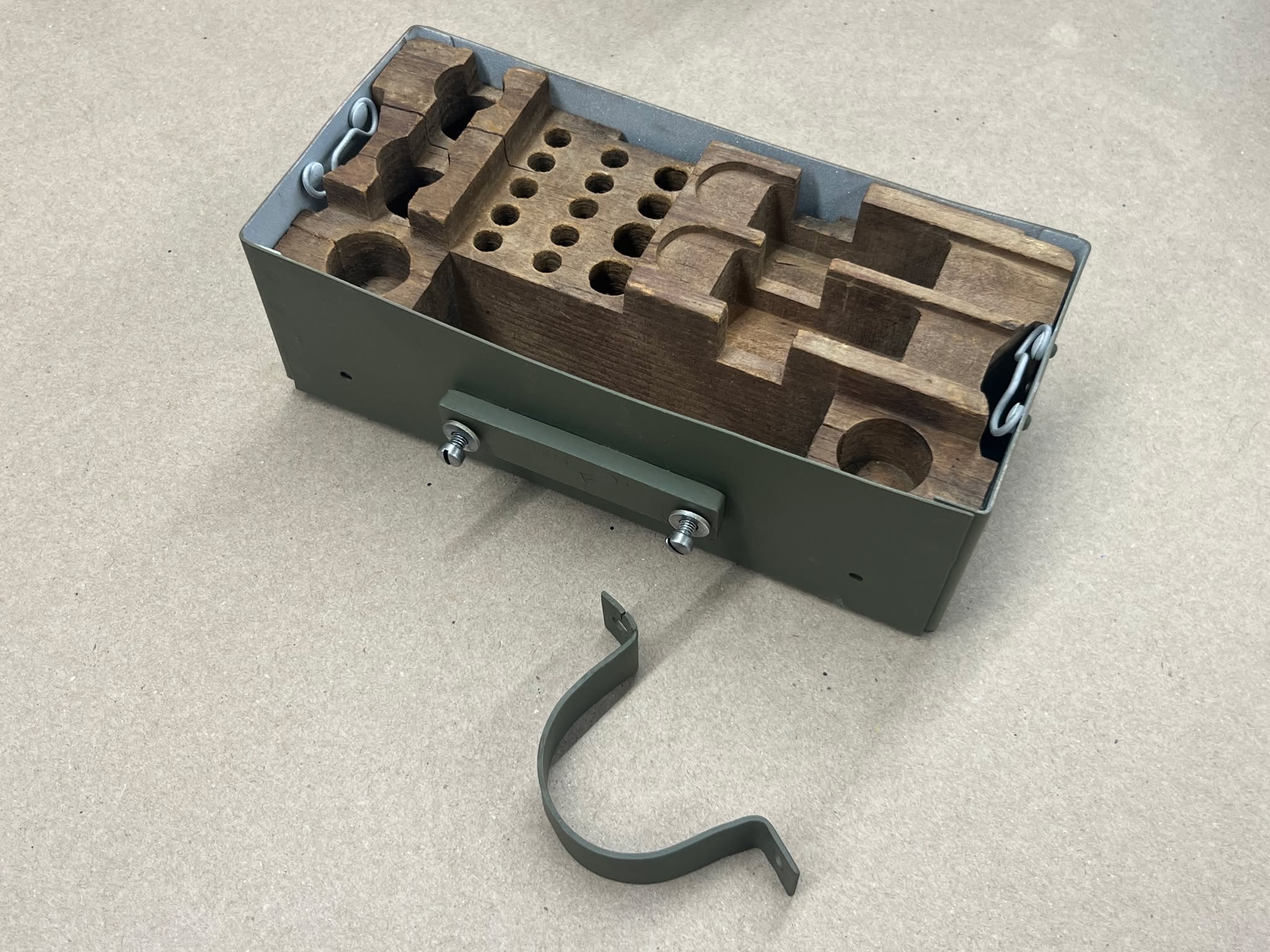
The Spare Parts Box for Lucky Thirteen undergoing restoration.
Photo taken 4 May 2026.
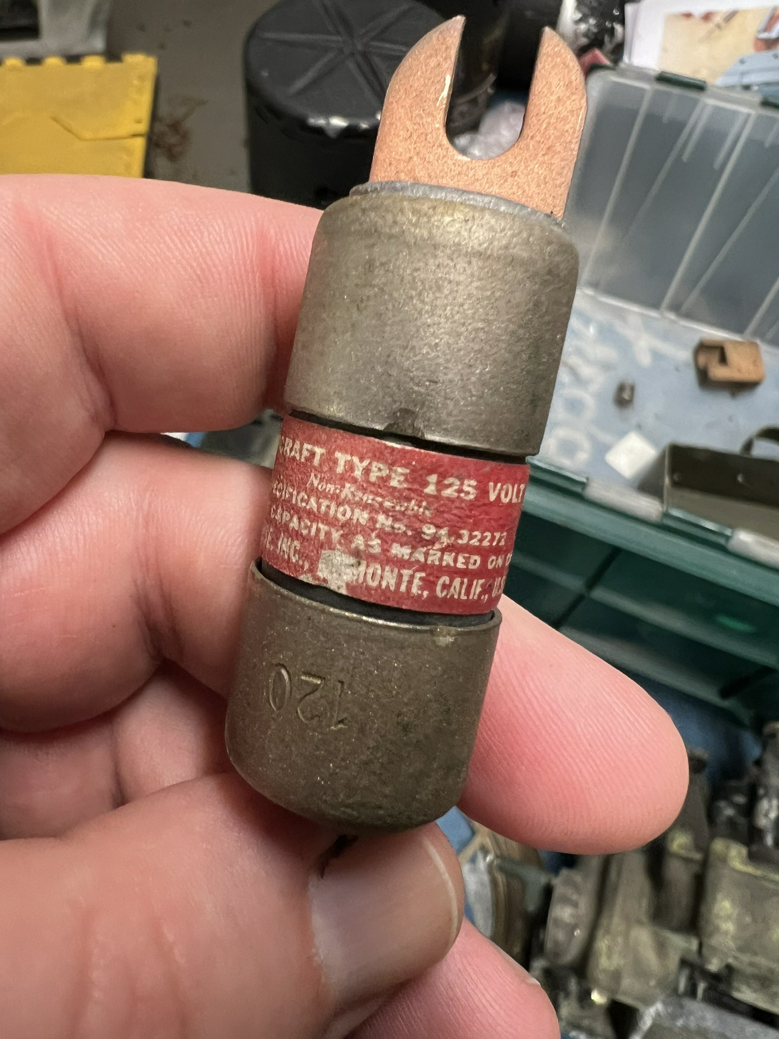
A wartime 125V/120A fuse in Fred’s collection with its original label still in place.
Maybe somebody out there has an example or two of this fuse?
Or perhaps, can help with the ACL-120 modern equivalent?
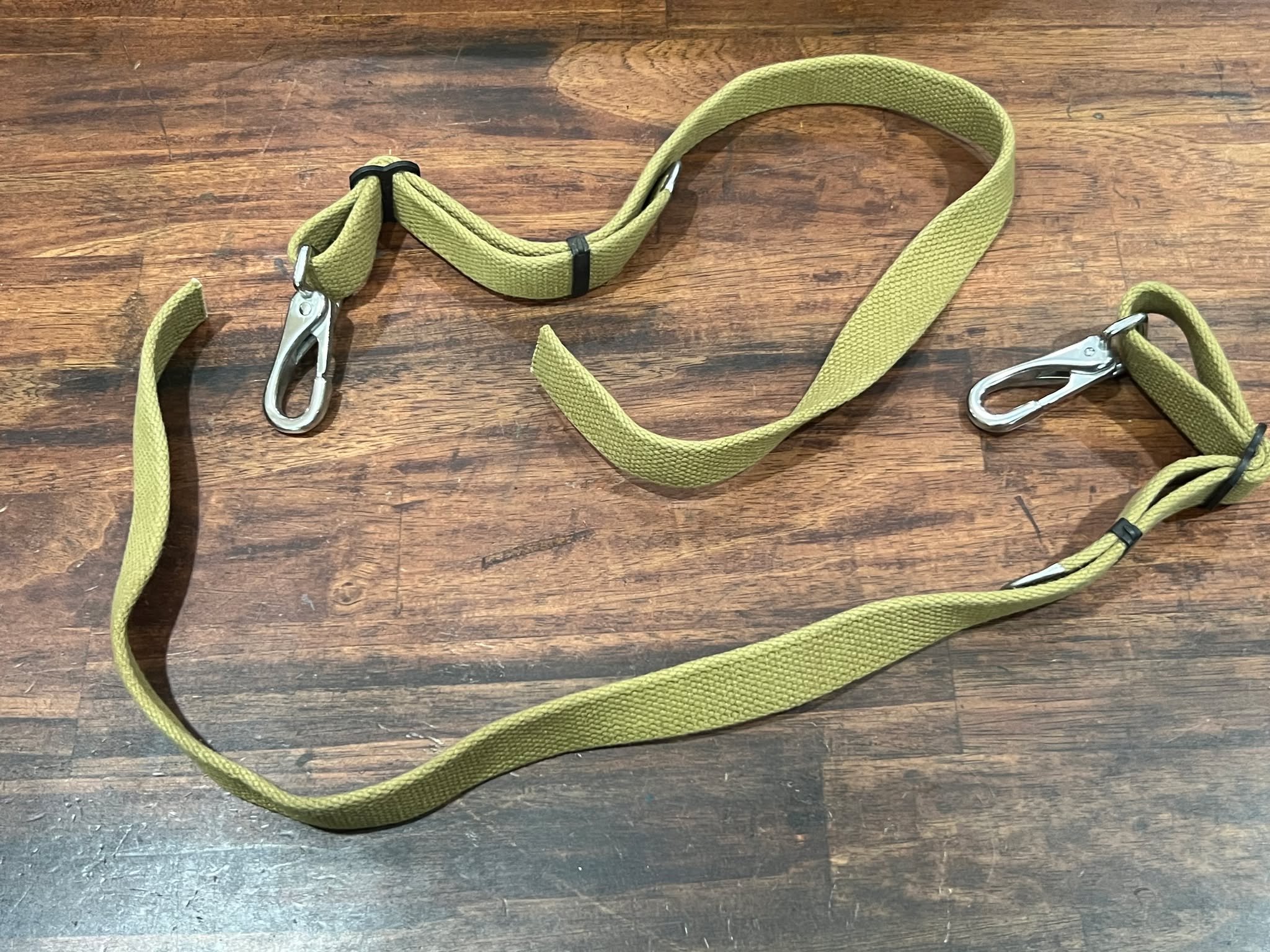
Another recent piece is the armor support strap for the tail stinger. A second was made for our friends with B-17E Desert Rat.
Photo taken 14 May 2026.
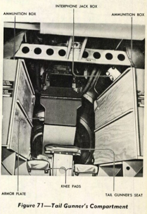
The B-17’s tail gun was the most heavily armored position on the aircraft. Whereas the other positions were protected by plates of 1/4″ steel plate, the tail gunner was protected by plates 5/16″ thick.
The plates in the tail were divided into thirds, with the center plate being on a hinge. Typically, the gunner knelt with his chest up against this plate, reaching around to use his .50 cal machine guns. If he should need access to the guns, however, this center plate could be turned upward out of the way.
That was the purpose of the strap.
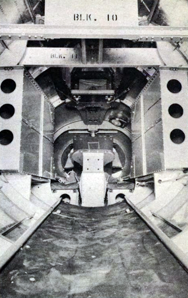
In this manual photo – taken aboard an older B-17 than the previous photo, based on the metal ammo boxes rather than wooden ones – the center armor plate is suspended upward by the support strap.
When not in use, the strap was clipped to the left wall.
If anyone can help with Lucky Thirteen‘s armor plate needs, please let us know!
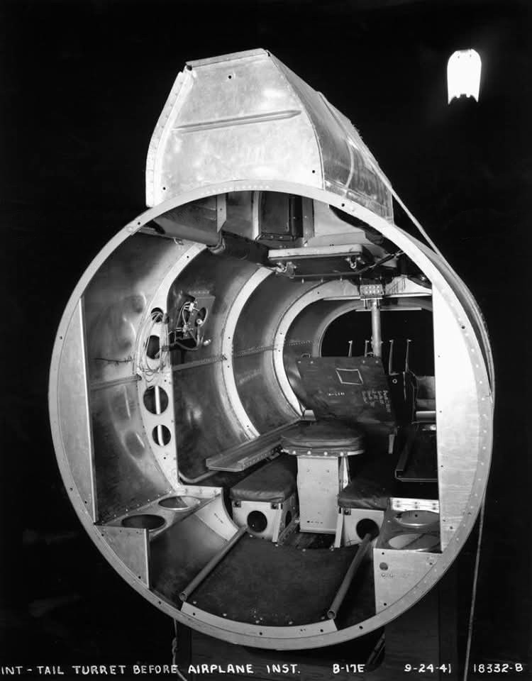
Factory photo of a B-17E stinger position, again with the hinged armor plate held up with its strap.
Note the pad on the hinged armor plate, for the tail gunner to rest his chest on.
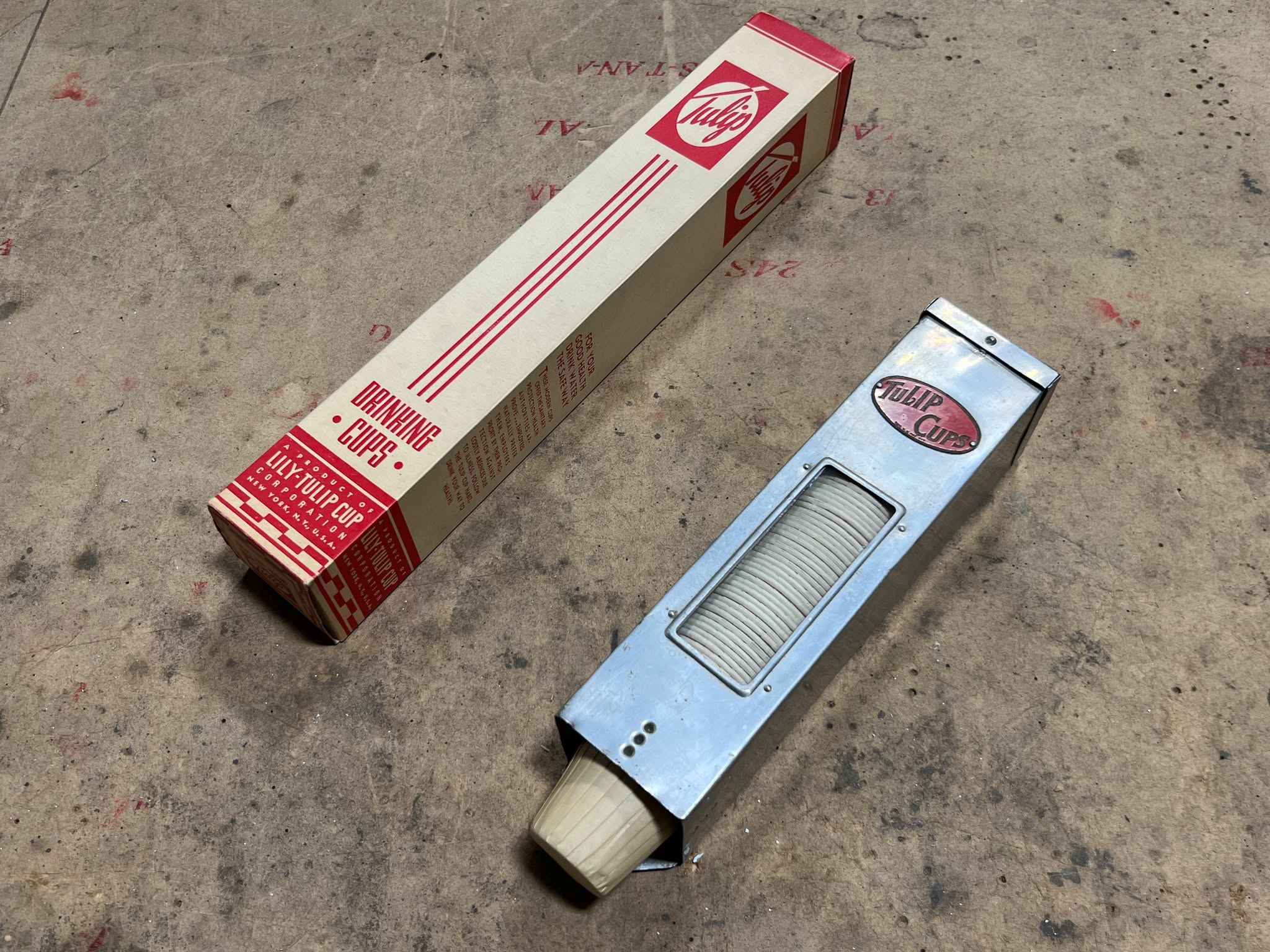
Back in December 2023 we managed to locate a Paper Cup Dispenser for Lucky Thirteen, after some six years of searching.
Now we have a set of original paper cups for it to hold!
Photo taken 16 May 2026.
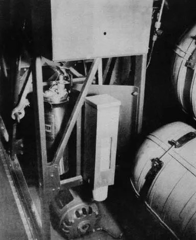
Manual illustration of the paper cup dispenser on the back of the co-pilot’s seat.
Nearby is a Type A-2 carbon tetrachloride fire extinguisher and one of the aircraft’s two power inverters.
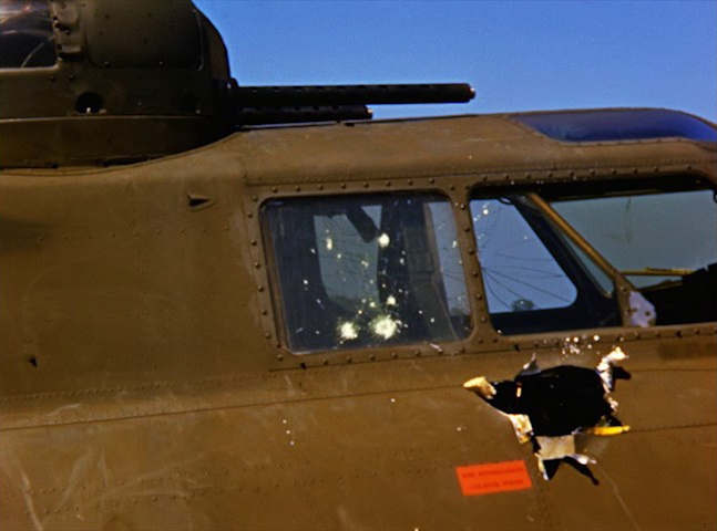
Screencap from William Wyler’s film Memphis Belle (1944) showing Old Bill (42-29673, 305BG).
Note the red decal by the cockpit window. This notes the presence of the A-2 extinguisher shown in the previous photo.
B-17Fs typically carried two A-2s, with the second either by the entry door in the waist, or in the radio compartment.
Footage dated 15 May 1943.
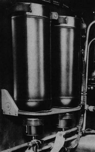
Manual illustration of the thermos rack, located behind the copilot’s seat, above the hydraulics panel.
We are always looking out for metal fabrication volunteers, and if anyone is interested, the thermos rack is one piece that we have long needed finished. Just let us know!

Because coffee is a natural diuretic and toilet facilities difficult to use at high altitudes, the thermos rack was removed with the B-17G.
Something else was needed to combat crew fatigue and candy became the obvious choice. As such, this piece ultimately entered service in 1944.
With the conclusion of the fundraiser, more parts were purchased for the ball turret.
The first of these was azimuth gear assembly for the right-hand ball support on the turret’s trunnion.
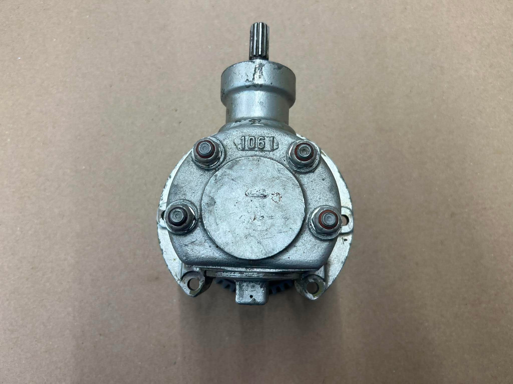
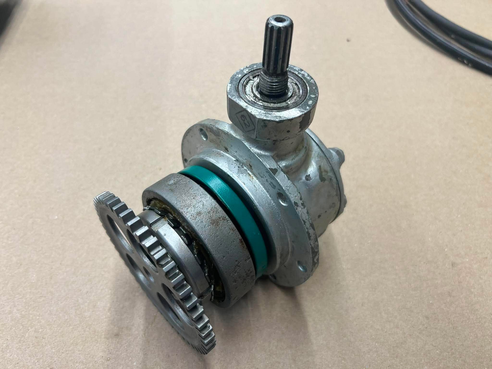
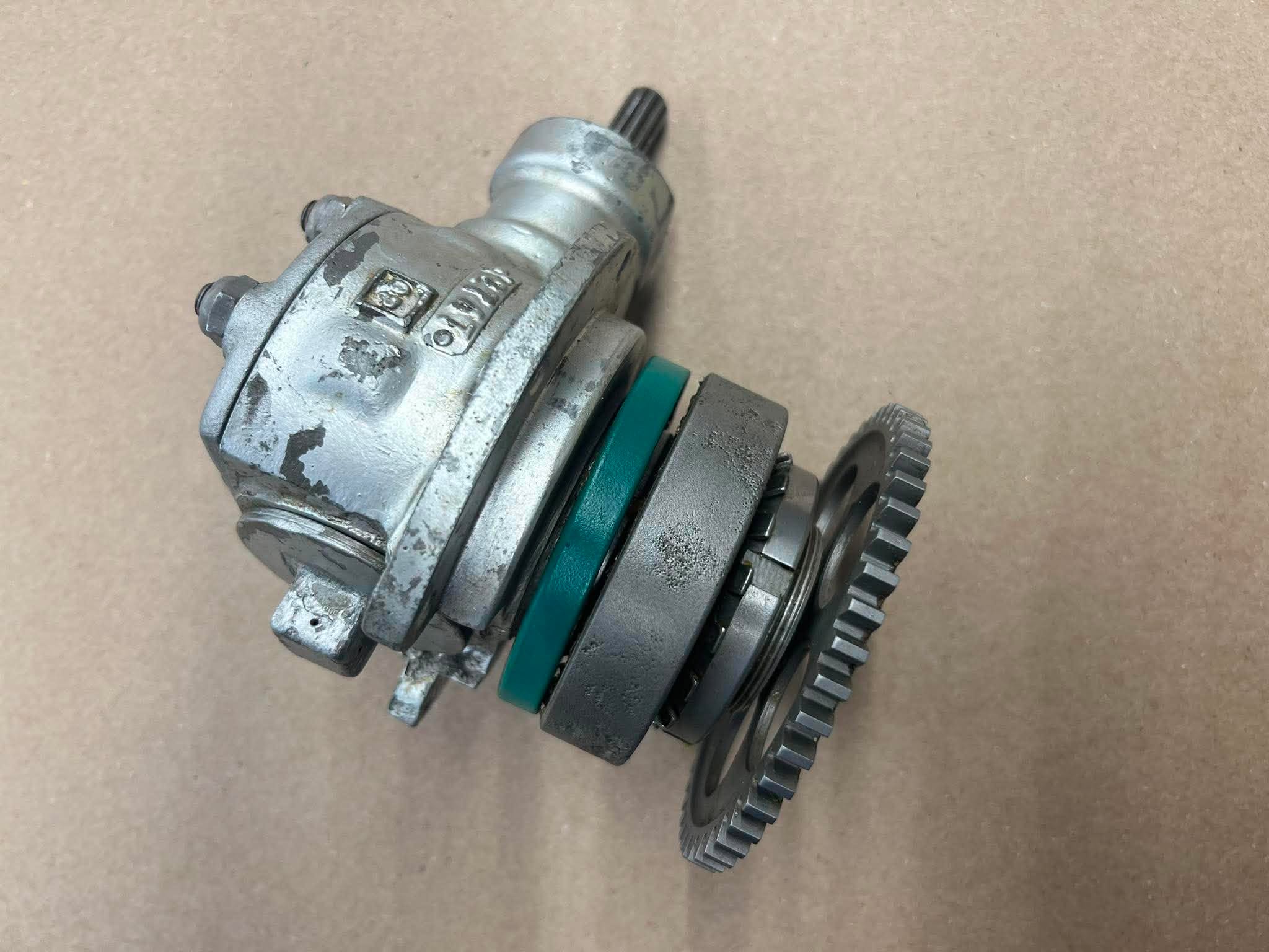
This particular example is from an A-2 though the cover plate has been altered.
A-2s had plexiglass covers on the side to improve airflow, being attached in the center to the cover plate on this gear. This cover plate has a piece of sheet metal stuck in the center and the hole underneath welded shut. This indicates it was made for the A-2 but altered for use on a later variant.
We will restore it to factory condition.
Photos taken 13 July 2026.
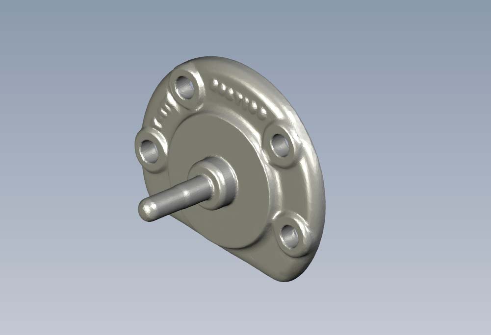
A rendering from when we 3D scanned an original A-2.
This shows how the cover plate originally appeared.
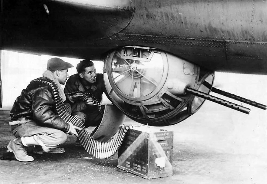
The center hub missing from the cover plate was used to attach the side covers unique to A-2s and the first 967 A-13s.
This photo is posed – there is no way to load the turret from outside the aircraft.
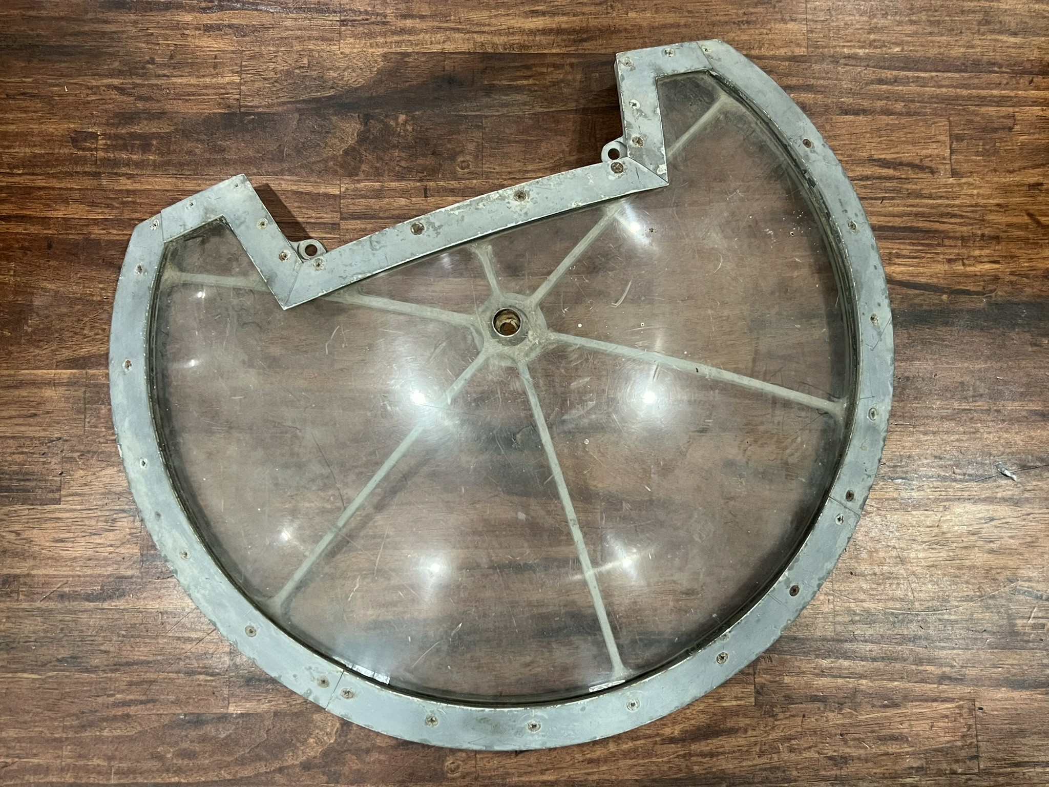
So far, we have managed to acquire just one original sidecap for the A-2 on Lucky Thirteen.
If necessary, we can use this as a pattern to make the other one.
Photo taken 2 March 2024
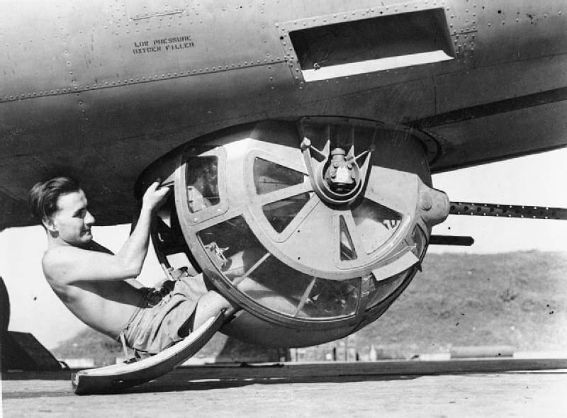
The right-hand ball support, with its azimuth gear assembly, can be seen in this photo.
The gear connects the two azimuth gears inside the ball, which are connected to the motor, to the azimuth pinion gear on the trunnion inside the airplane. The azimuth pinion gear is what actually rotates the turret.
This photo shows an RAF airmen with an A-13 ball on a Consolidated B-24 in the China-Burma-India Theater or Operations.
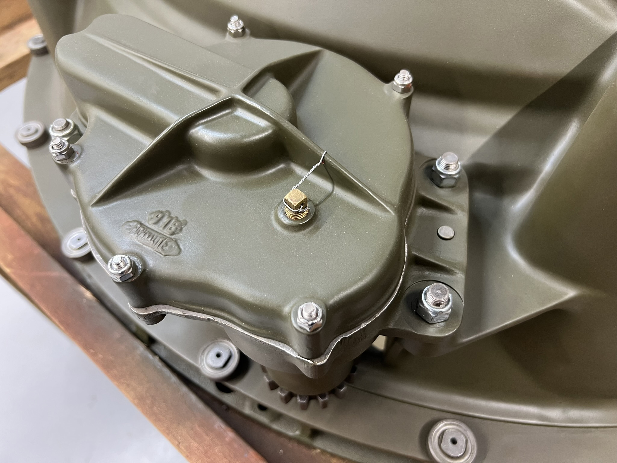
Close-up of the azimuth pinion gear.
This is the gear which grabs the azimuth ring which, in turn, rotates the turret.
Photo taken 6 August 2025
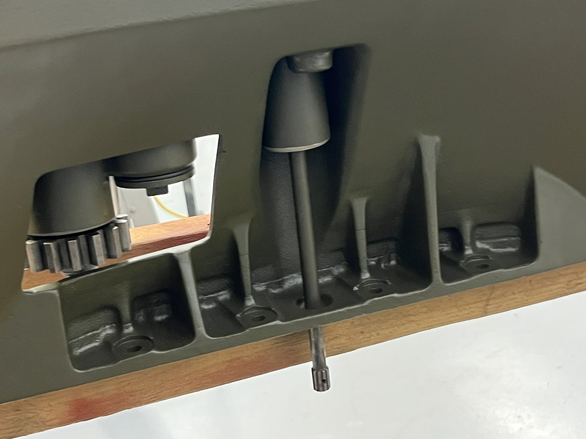
Interior view of the trunnion, showing where the azimuth pinion gear attaches.
The pinion, visible here, feeds down through the two turret support bracket on the side of the ball. A linkage piece connects the pinion to the shaft atop the newly acquired external azimuth gear.
It is likely that a new linkage will have to be machined.
Photo taken 7 July 2025.
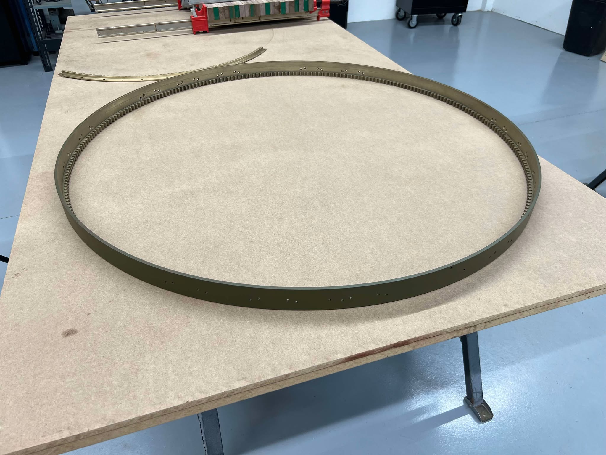
The azimuth ring from Lucky Thirteen‘s ball turret is removed and cleaned.
The brackets which mount this ring to the floor of the B-17 were too corroded to be reused. Molds were made by volunteer Bob Hachmann and new brackets cast by our friends at Windy Hill Foundry.
You can see them doing so here.
The next step will be to machine the castings and mount them to the ring.
Speaking of the azimuth ring, said ring also held the aircraft’s fire cut-off cam.
The ball turret’s fire cut-off cam was made of pressed stainless steel and prevented the ball from firing on its own aircraft.
Again, since it is unlikely that an original will become available, we are currently working to recreate this piece.
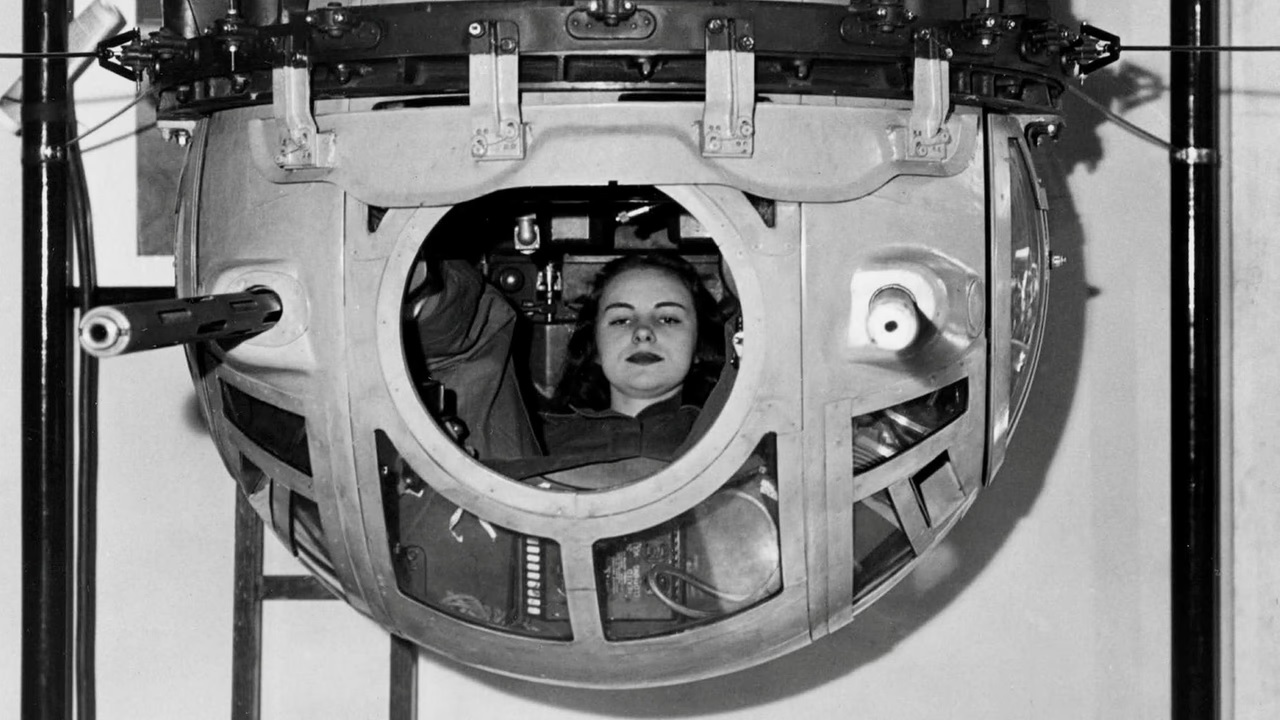
This is a Sperry photo of an early ball prototype. Note the cooling jackets on the guns, showing the distinctive early cut-out pattern.
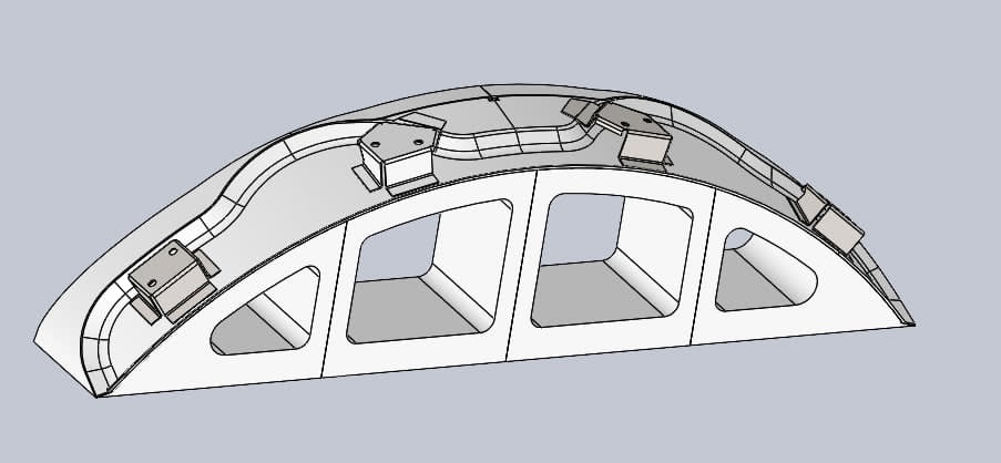
The fire cut-off cam was amongst the blueprints we ordered from the Smithsonian.
This CAD-model was made for 3D printing, the idea being to create a model with which to compare measurements with originals on display (as the blueprints were lacking in detail).
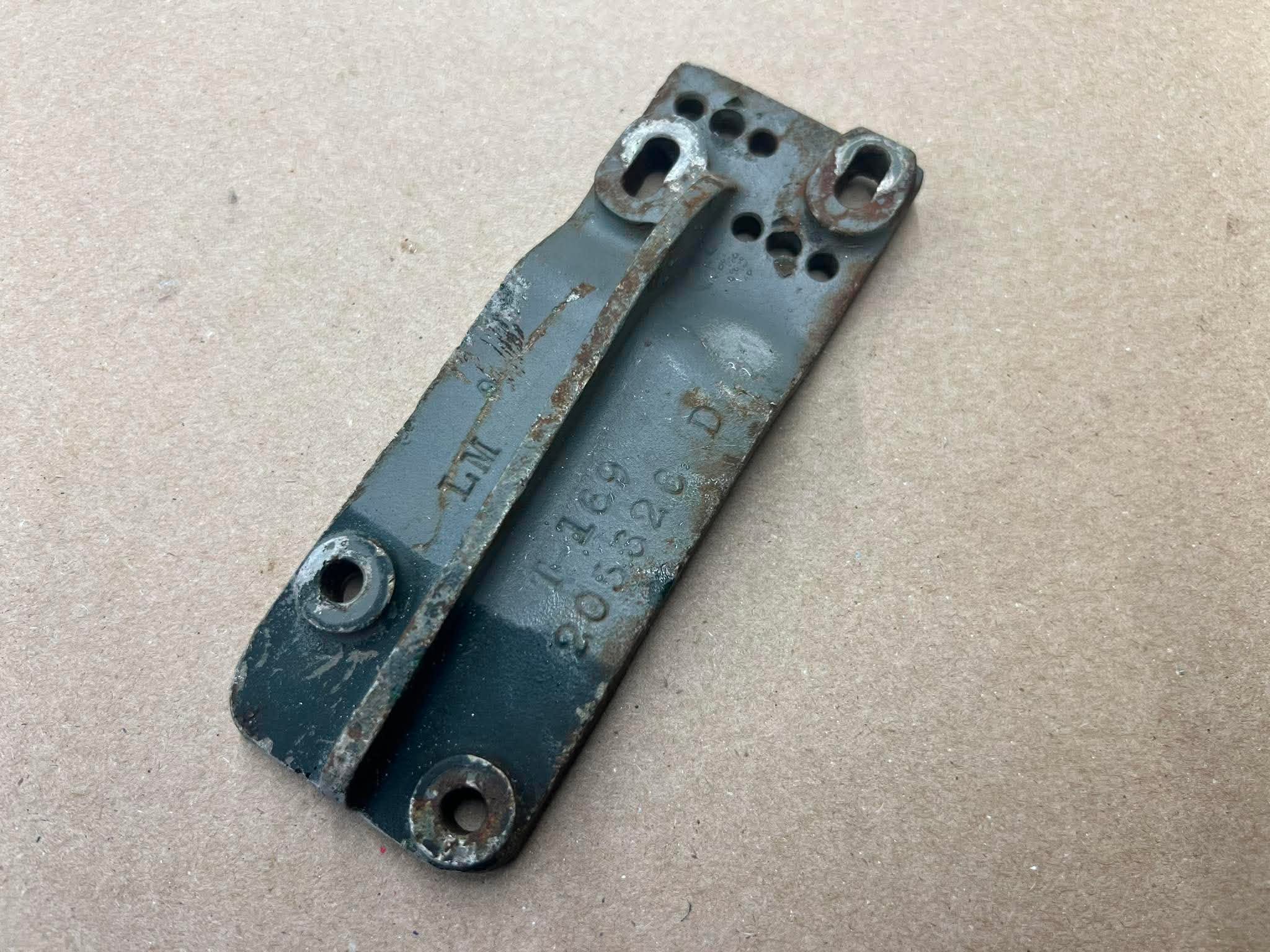
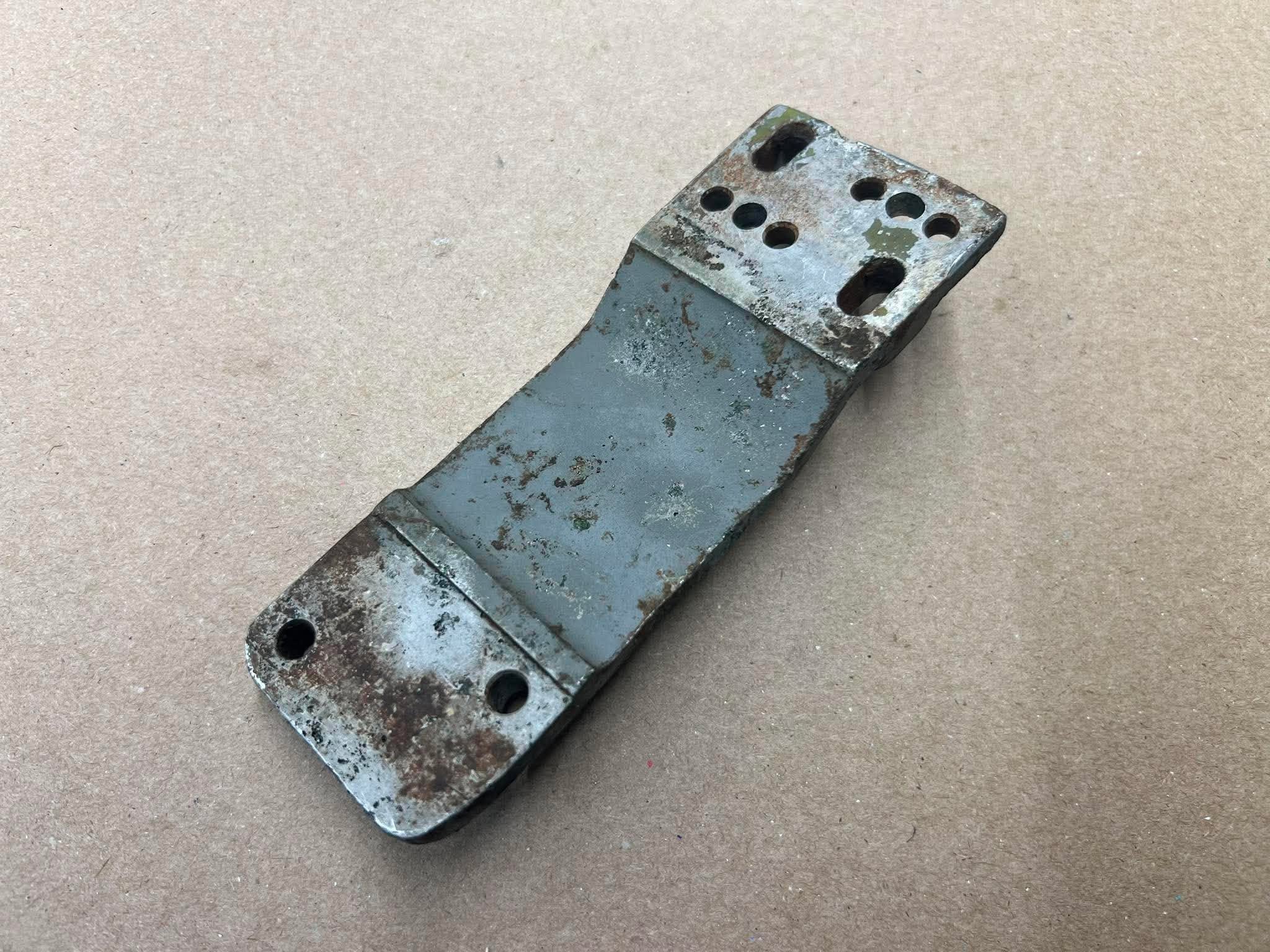
An original fire cut-off cam bracket, which we purchased so that we could use it as a pattern in creating new brackets.
Early turrets had cast cut-off cam brackets; later turrets had ones made of pressed steel.
Photos taken 13 June 2026.
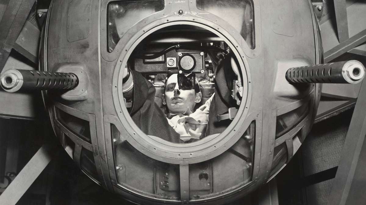
The fire cut-off cam was the simplest form of a gunfire interrupter.
Above the center glass panel is a nipple – this is the fire cut-off switch. When the turret rotates to a position where its guns might hit the bomber, the nipple will be depressed by the stainless steel cam mentioned earlier.
By depressing this button, the turret’s gunfire is halted.
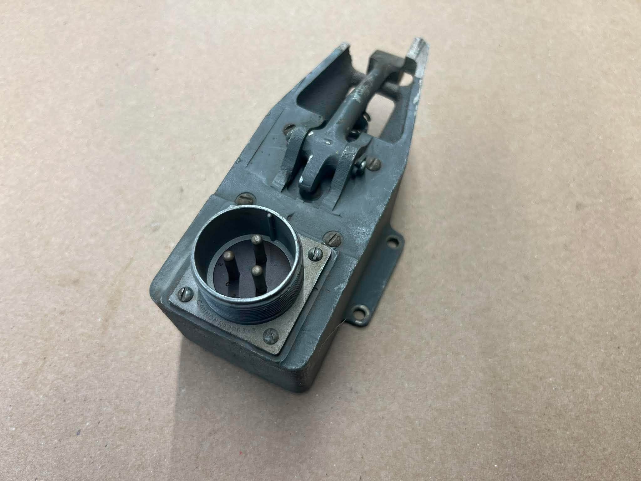
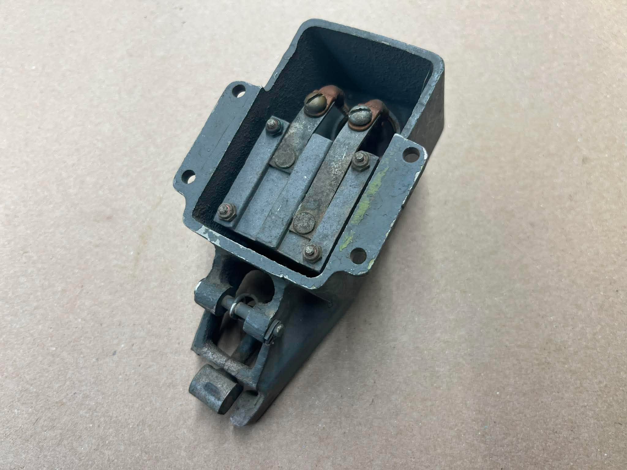
The newly acquired fire cut-off switch for Lucky Thirteen‘s Type A-2 Ball Turret.
While a small piece of casting is broken away, the electrical connector still functions perfectly.
The rocker arm on this piece connects to the nipple on the outside of the turret.
Photos taken 13 June 2026.
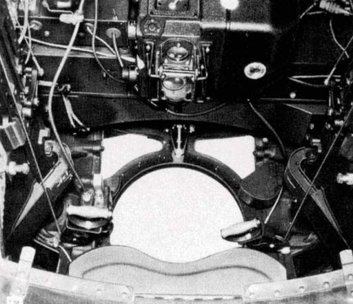
The fire cut-off switch can be seen just above the center window in this ball turret.
As evidenced by the dark green paint, this is an Emerson-built turret rather than a Briggs.
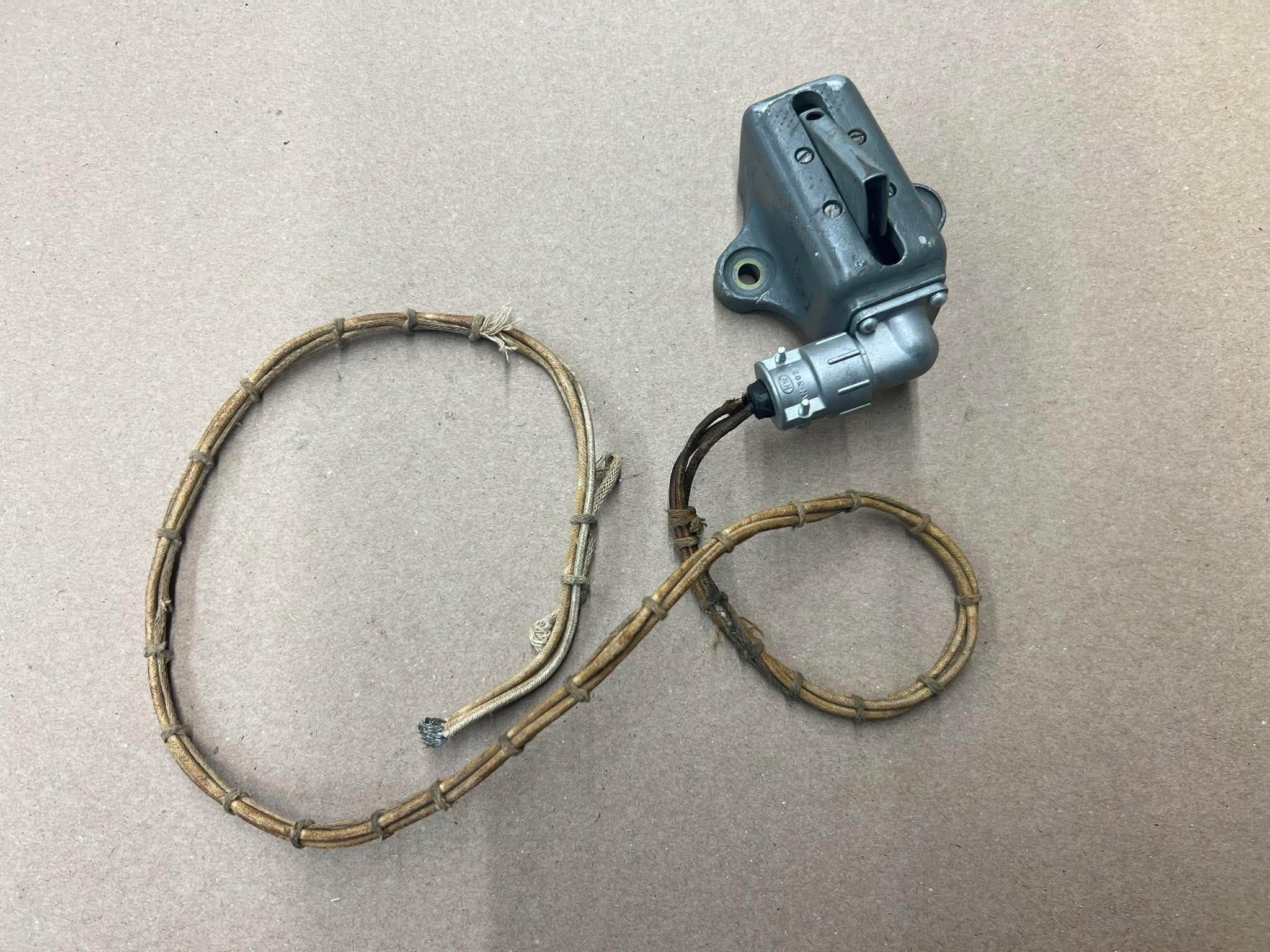
A switch of a different kind…
The newly-acquired push-to-talk switch for Lucky Thirteen‘s Type A-2 Ball Turret.
Depressing this switch activated the intercom for the ball turret gunner.
Photo taken 13 June 2026.
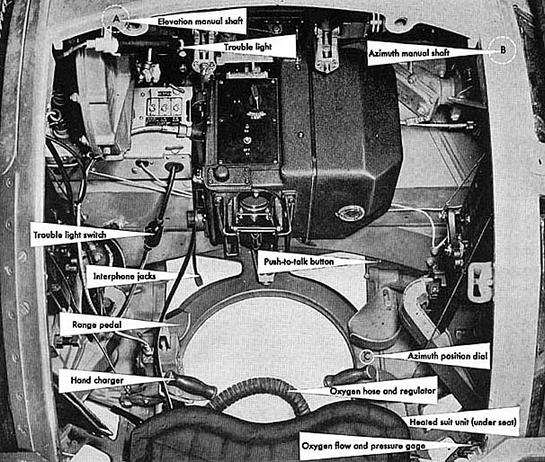
The push-to-talk switch in the ball turret was operated by the gunner’s right foot. Resting his heel in a cup, he could tap the switch with his toe to talk.
The turret in this manual illustration is a Briggs-built A-2A or A-13. The giveaway are the electrical connections for the trouble light and gunfire solenoids at the bottom of the fuse box. Here they are hard-wired, but on older turrets each had their own electrical connector.
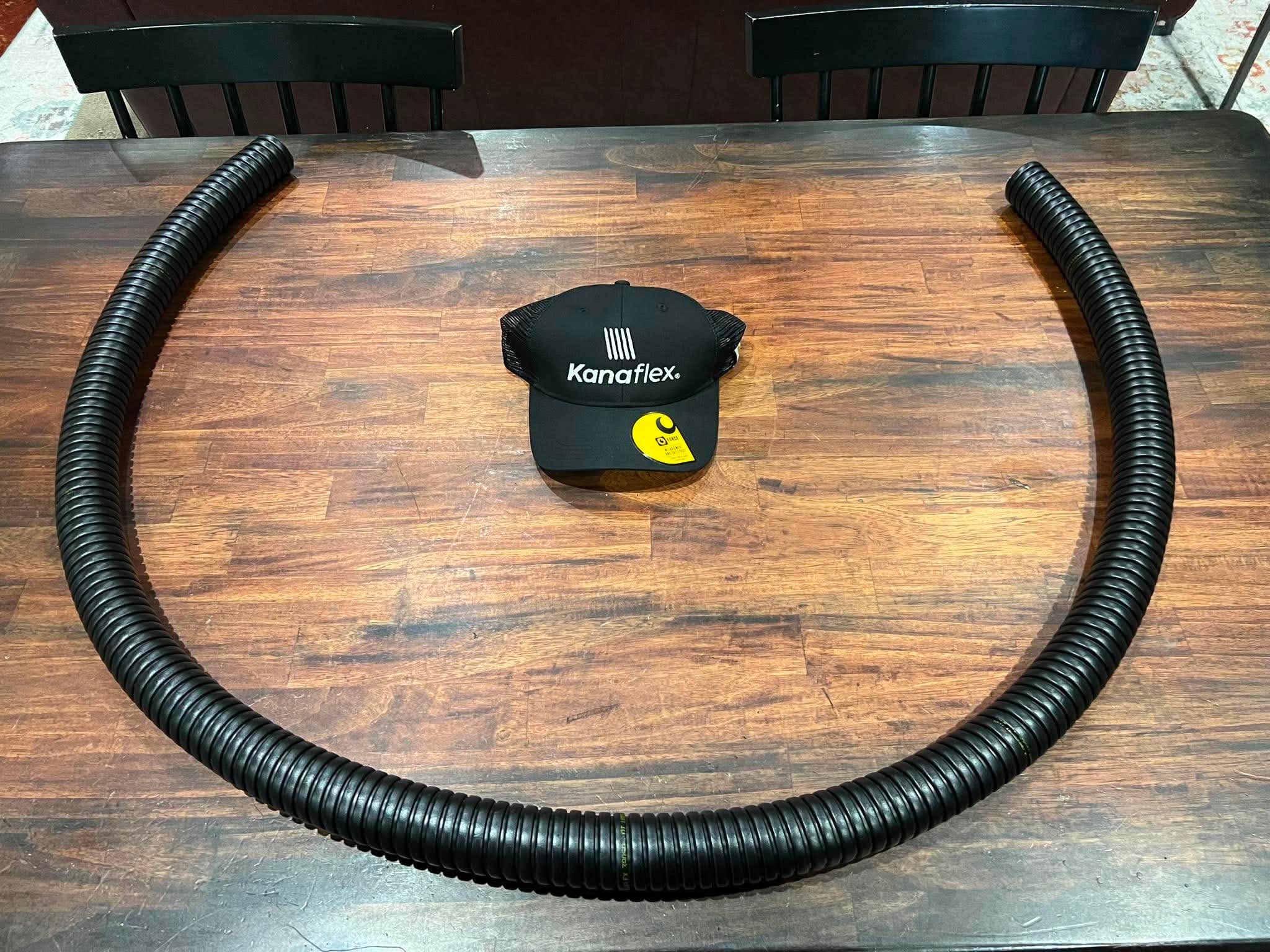
And on the subject of electrical lines, we now have the correct hose for the ball turret’s main power conduit.
A subject that has plagued us for a while, one of the blueprints we ordered from the Smithsonian was the spec sheet for the turret’s conduit, in the hopes that it would help us find a suitable match. And it did.
This hose comes to us from the Kanaflex Corporation of Vernon Hills, Illinois. This is a piece rarely seen on surviving ball turrets so we are incredibly thankful to Kanaflex for helping us recreate this piece of history!
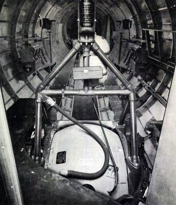
Power from the turret entered the ball through this length of rubber hose, protecting the electrical lines inside.
The smaller rubber hose is the turret’s oxygen line. External oxygen feeds were only a characteristic of Type A-2 ball turrets; later variants – the A-2A, A-13, and A-13 – all had oxygen swivels to feed in oxygen from the aircraft’s primary supply.
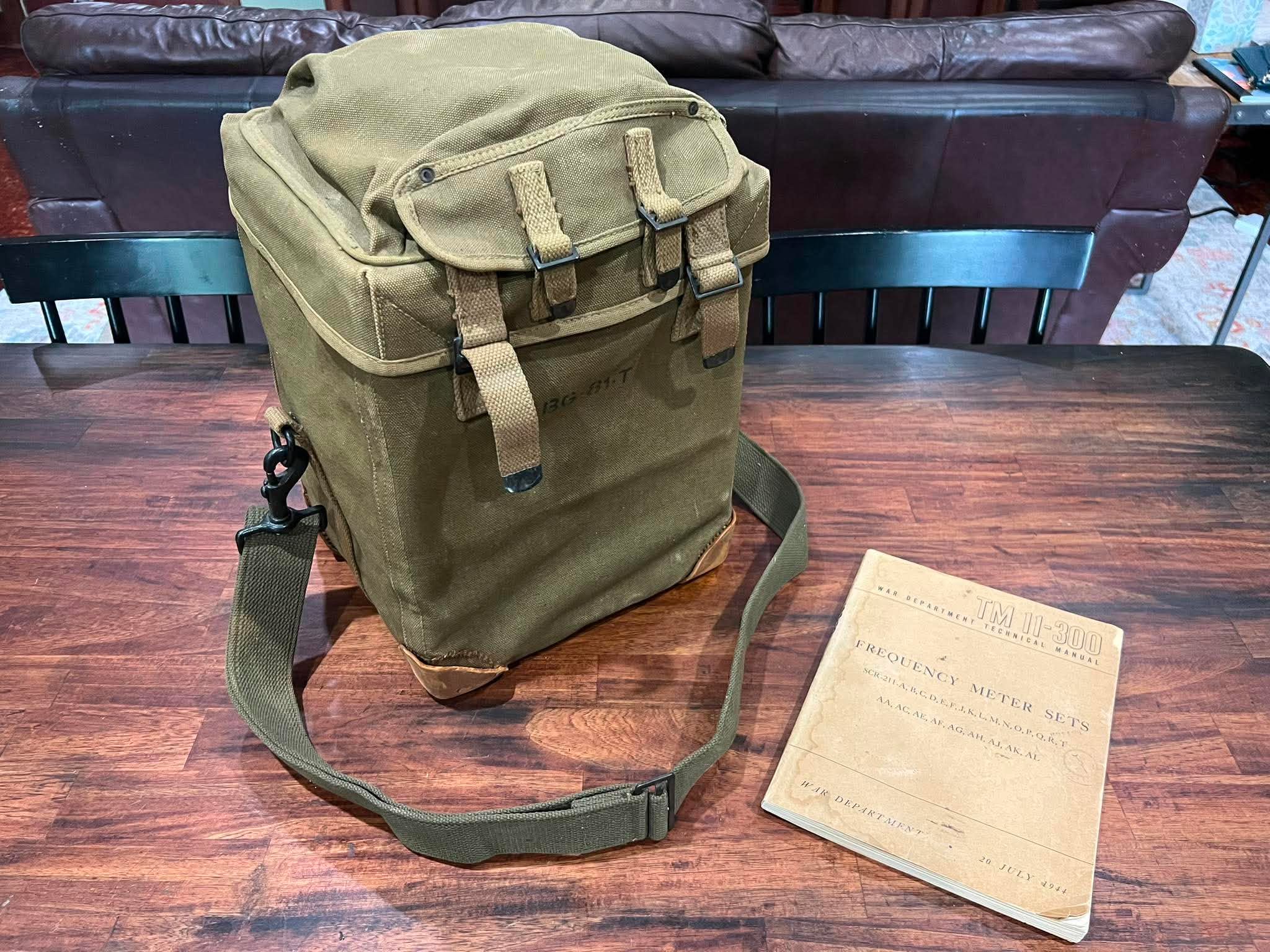
A donation of a different sort recently came to us from our friend Ken Kinderman of Bronxville, New York.
This is the SCR-211 Frequency Meter for Lucky Thirteen.
Photo taken 10 July 2026.
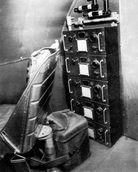
This factory image, taken aboard a B-17E, shows the frequency meter strapped to one of the radio compartment’s passenger seats. These seats were almost always removed from combat aircraft as they interfered with ditching procedure.
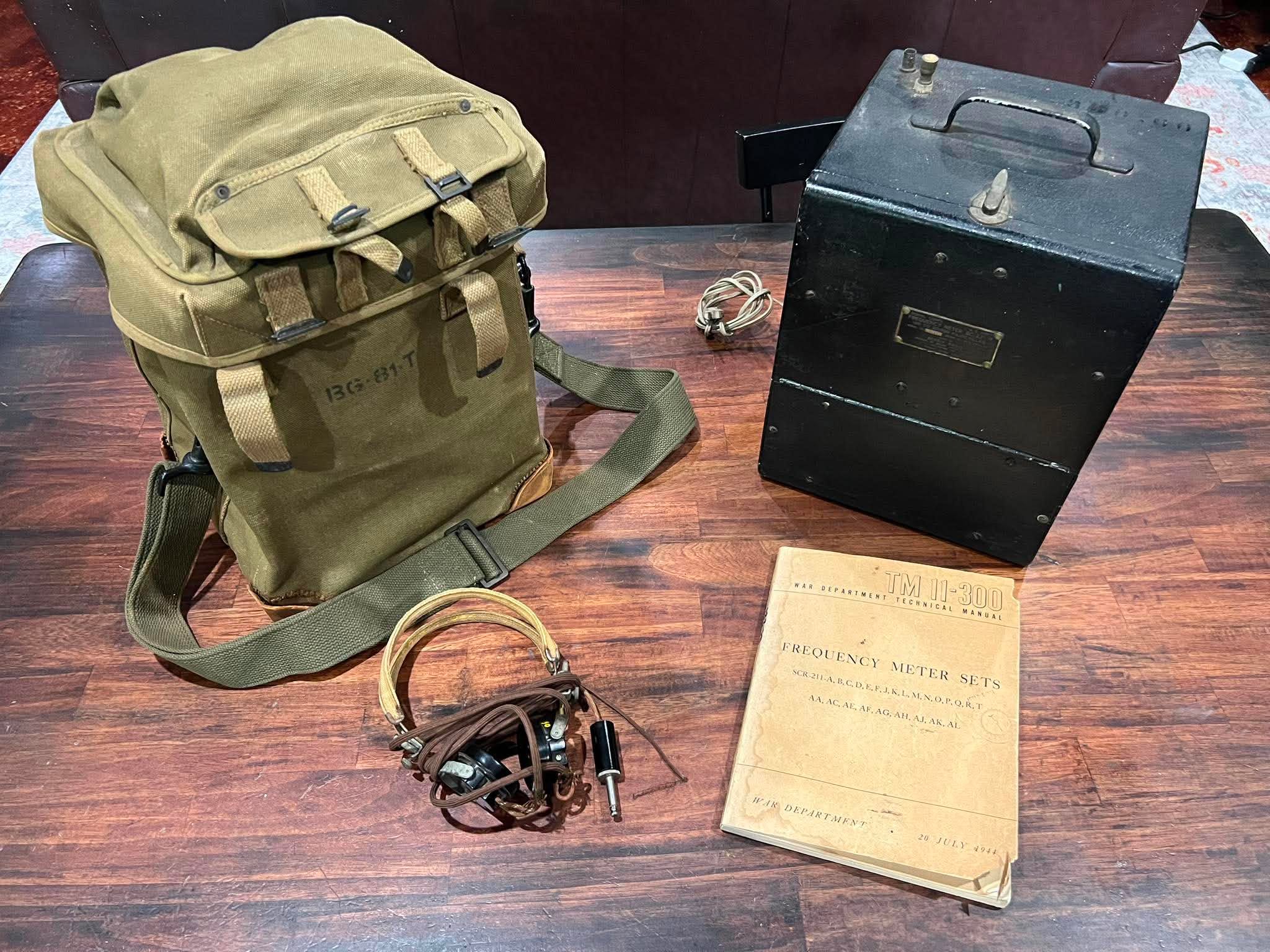
A standard SCR-211 setup included the BC-221 Frequency Meter, its BG-81 Bag, and a pair of headphones.
Ken’s donation included all these pieces, along with its original manual.
BC-221s came in both black metal and green wood varieties.
Photo taken 10 July 2026.
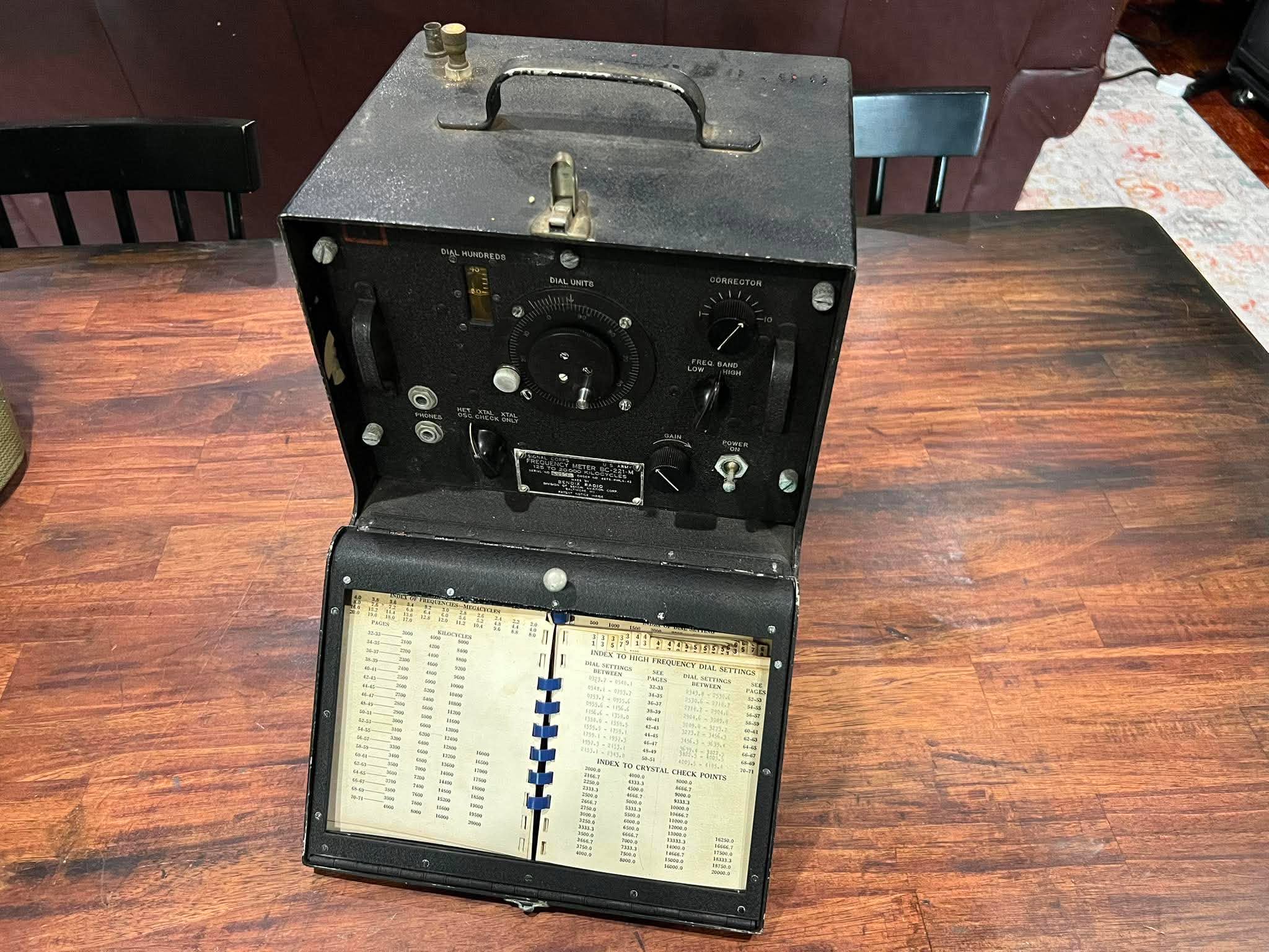
A fine tuning instrument critical for radio calibration, each BC-221 carried a frequency settings booklet unique to that unit.
The fact that the booklet on this example remains intact is quite special.
Photo taken 10 June 2026.
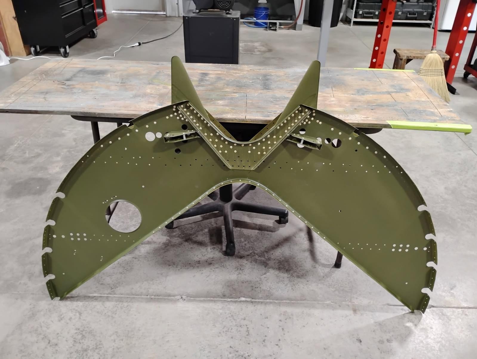
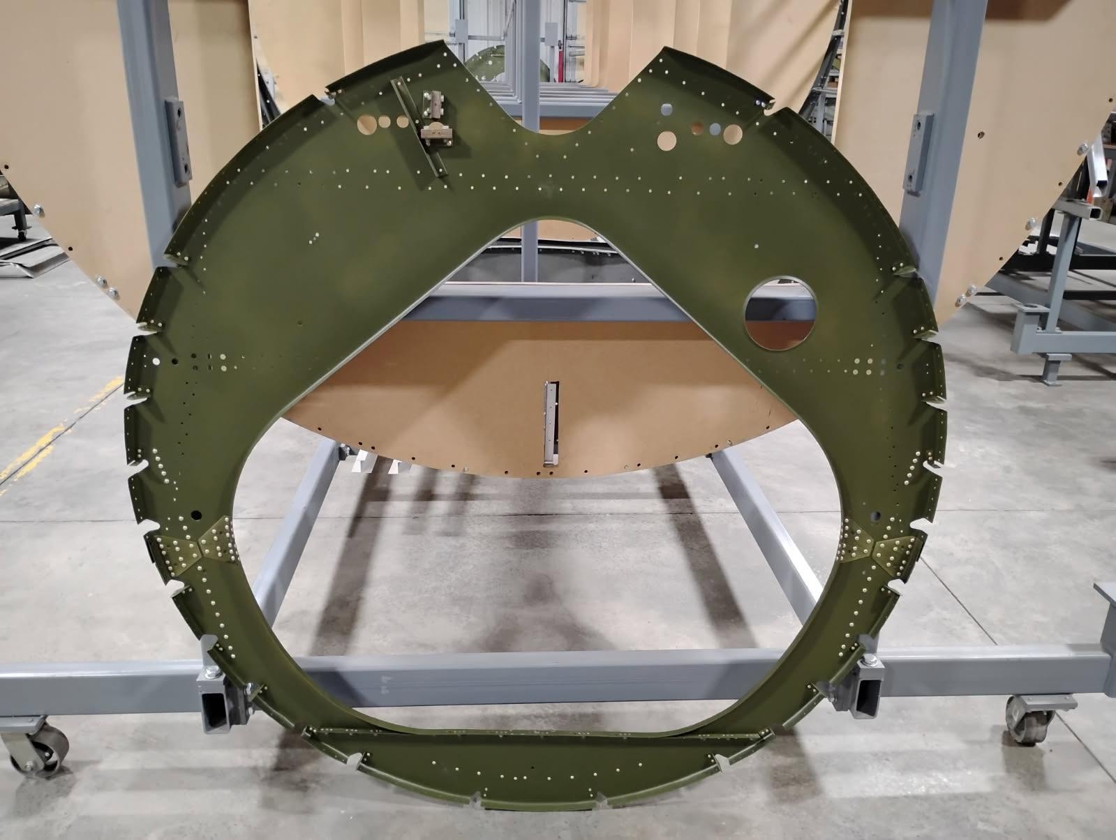
I thought I would share some more pics from Ray, working on Sta. 8 of Lucky Thirteen.
Sta. 8 is the bulkhead in the tail where the carry-thrus for the horizontal stabilizers (i.e., tail fins) come through. In keeping with Douglas practice (who license-built Lucky Thirteen for Boeing), much of this bulkhead is dipped in zinc chromate, while the surrounding skins are left bare aluminum. Sta. 8 is the most complex of the bulkheads in the tail, due to it holding the carry-thru spars. In preparation for finishing, these spars have been given an acid wash.
Photos taken 15 June 2026.
The Hangar Thirteen Foundation is a 501c3 nonprofit charity dedicated to bringing back a B-17F representative of the bloody counter-air campaign of June 1943 through March 1944. Donations to this project are tax deductible. If you can spare a little to help this project, you can guarantee that you will see the results on Facebook and here on our website.
You can contribute through the Donate page or, to avoid a PayPal fee, you can send something via the mail to:
Gerad Allen Blume
Hangar Thirteen Foundation
442 Old Chalk Bed Road
Batesburg, SC 29006
Volunteers are also always welcome. In fact, you need not be an Asheville resident – you can work from home! Persons skilled with metal fabrication, machining, CAD modeling, metal casting, 3D scanning, and laser/waterjet cutting, are particularly helpful. Just reach out to us to get started.
Keep the show on the road!