
Back in May we did our annual fundraiser, this time focusing on the money needed to purchase a bombsight stabilizer.
You see, one of our goals is to restore Lucky Thirteen‘s Type C-1 Autopilot as we know of only two complete, working examples in existence today: one in France and one in Australia. To that end we have made excellent progress, but the main piece we still lack is the stabilizer.
Because of this, when longtime friend Andy Rivera offered us a Norden bombsight years ago, we asked him to hold onto it for a while. Part of it was the enormity of the piece in question, but the other part was simple: where would we mount it?
Well, I recently had the opportunity to travel to the Smithsonian National Air & Space Museum for a special visit with the collections and restoration staff. I got to crawl around Shoo Shoo Baby (42-32076, 91BG) and give my thoughts, as well as see the inner workings of the organization. Truly an awesome experience.
Since Washington DC is a great deal closer to Andy than the Carolinas, he took the opportunity to bring the Norden down. After all, with the May fundraiser, it is now just a matter of waiting for the stabilizer to arrive.
My friends, Lucky Thirteen has her Norden bombsight. Special thanks to Andy Rivera for this incredible piece!
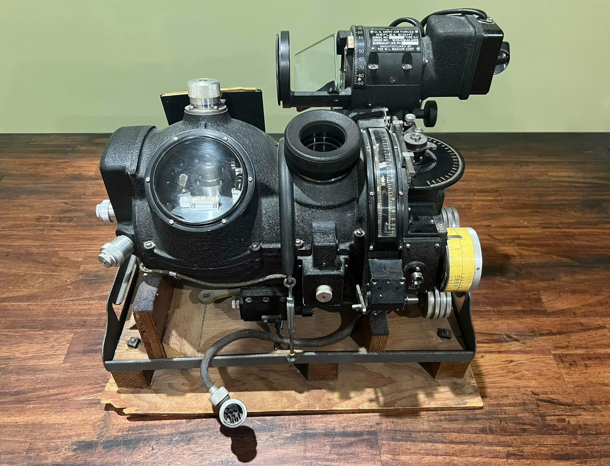
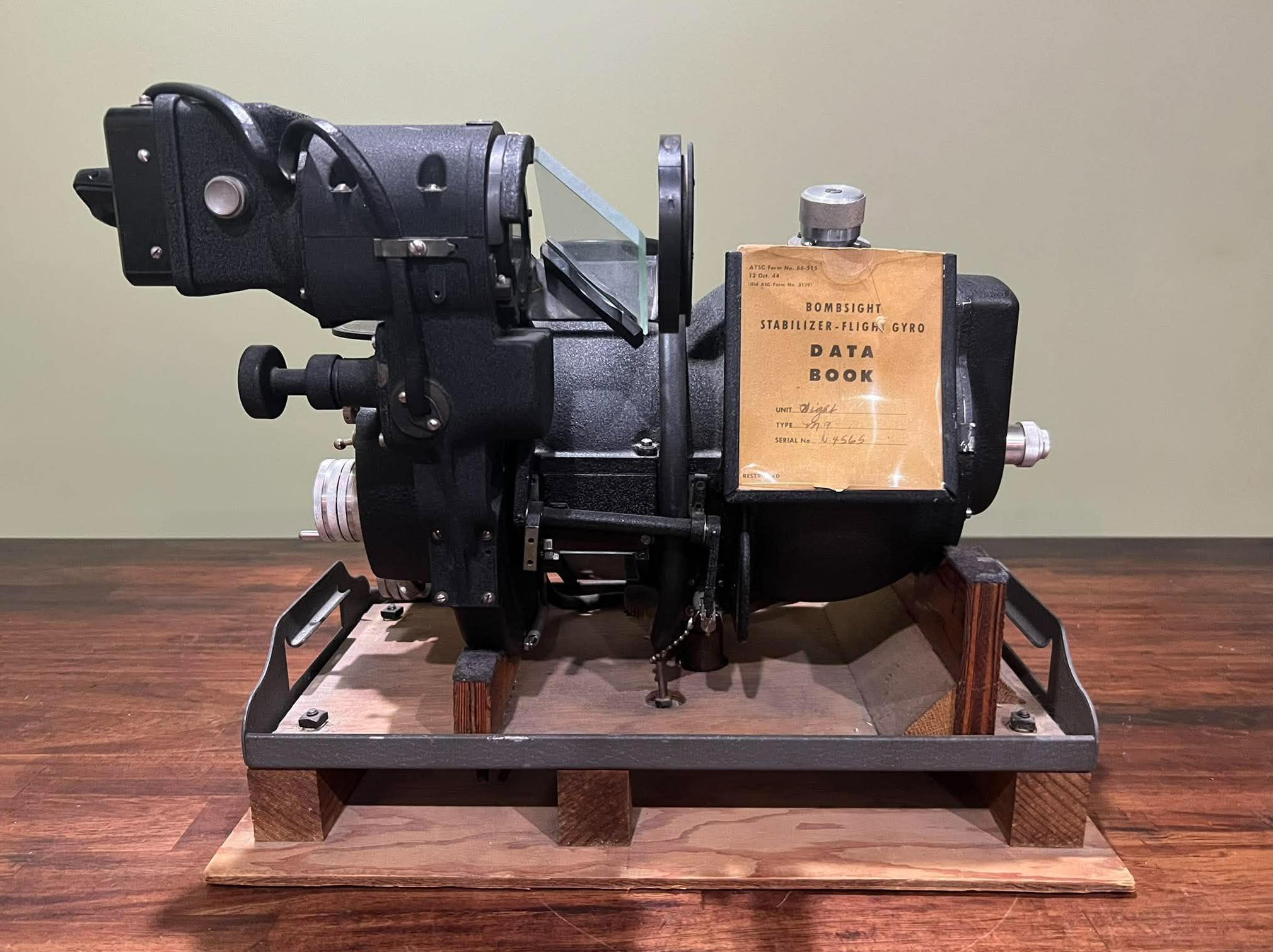
The newly donated Type M-9B Norden bombsight.
This particular example was manufactured by the Lukas-Harold Corporation of Indianapolis, Indiana, a subsidiary of Norden Laboratories of New York. This facility was built in 1941 and operated between 1943 and 1945, being assimilated into the US Navy after the war.
Photos taken 1 November 2026.
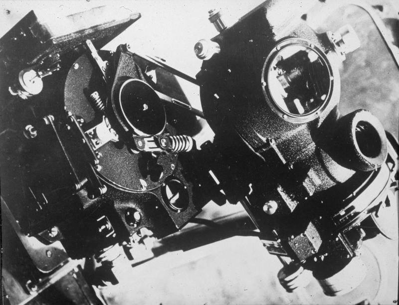
One of the first photographs of the Norden bombsight shown to the public, released on 17 November 1944. The lower portion is part of the Honeywell C-1 autopilot system.
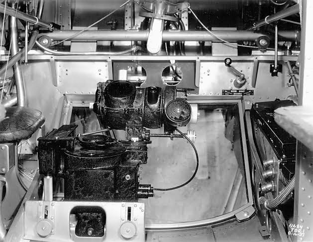
An early Norden bombsight aboard a US Navy TBD Devastator.
The Norden bombsight was originally developed for the Navy, its accuracy intended to pinpoint naval vessels. Carl Norden was originally an engineer with Sperry Gyroscope, having developed a bombsight with a Pilot’s Direction Indicator (PDI) in 1924. This was upgraded in 1930 with an analog computer design which calculated time-of-drop internally, eliminating the human factor by having the bombardier merely input variables such as altitude, airspeed, and drift.
Army interest in the bombsight was bitterly resisted by the Navy, who had legal precedence in Norden procurement. Army frustration with this arrangement saw them turn to Sperry to develop their own computing sight in 1937. The rivalry was finally put to rest on 4 August 1943 when the Army standardized the Norden over the Sperry following the embarrassing revelation that the Navy closed facilities storing surplus Nordens the previous May.
Much of the preference for the Norden over the Sperry is due to Norden CEO Ted Barth. While the sight was classified ‘top secret’ – to the point that photography was prohibited and its operators required to take loyalty oaths – its existence was nevertheless played-up, famously claiming that the sight was capable of “putting a bomb in a pickle barrel.” The Norden was indeed capable of uncanny accuracy and remained in usage as late as the Vietnam War. However, poor European weather negated the positive results often found in the clear skies of the American West, with an average target error of 1,673 ft complicating the fact that the standard AN-M64 500 lb bomb only left, on average, a 20 ft crater.
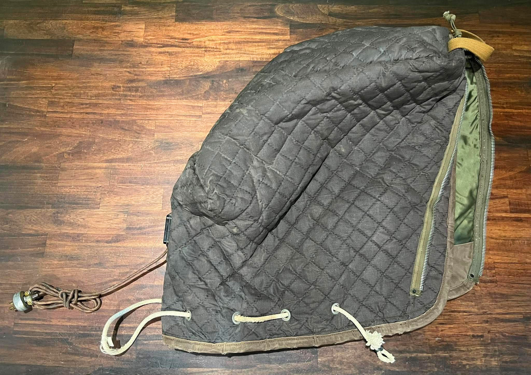
Andy’s donation of a NOS Norden bombsight came complete with an electric cover.
This plugged into the bombardier’s heated flightsuit rheostat and was used to prevent potential component freezing caused by subzero temperatures.
Photo taken 1 November 2026.
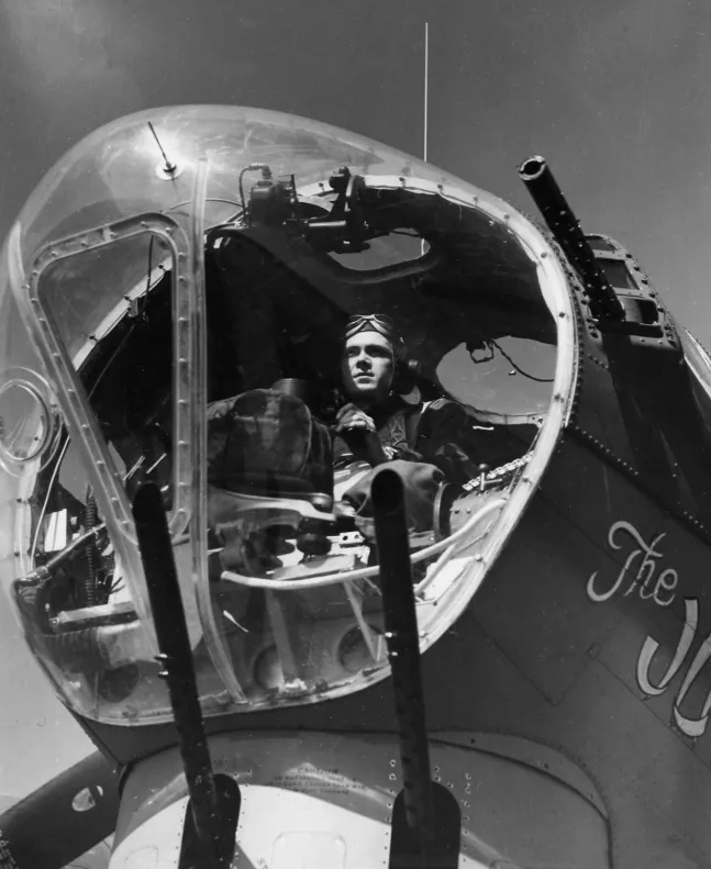
1LT William E. Sticklen poses aboard The Jub Jub Bird (42-31883, 91BG). The Jub Jub Bird exploded over Leipzig on 2 November 1944.
The heated cover can be seen on the bombsight’s stabilizer.
When not in use, Nordens were stored in lockers at a safe building on each airbase. Generally, only two or three aircraft in a group would carry a Norden on a given strike, the rest simply ‘bombing on the leader.’ As such, the others in the group flew with the arrangement shown above.
Recently, a friend of ours located a source for NOS RS-2 Relays. Thankfully they were at a reasonable price and, being NOS, their condition top notch. The wax sealant on the connectors show that the casings have never been opened.
RS-2 relays are rarely seen in restorations, but were mounted above the navigator’s desk in wartime. Made by P.R. Mallory of Indianapolis, Indiana, the letters “RS” are for “rack selector.” Working with the aircraft’s intervalometer, the relays cause the bombs to be released so as to cause minimal disturbance to the aircraft’s equilibrium. The two work in tandem, transferring release impulses in the following sequence:
Left Internal Bay
Right External Rack
Right Internal Bay
Left External Rack
Left Internal Bay
Right Internal Bay
And so on.
Four relays in each bomb rack selector transfer impulses into the four racks. When each rack is empty, or when a bomb fails to release and those above must not be dropped, the relay automatically excludes the rack from the circuit so there are no dead impulses. Each of the four rack circuits can be turned off separately by its switch on the bombardier’s panel.
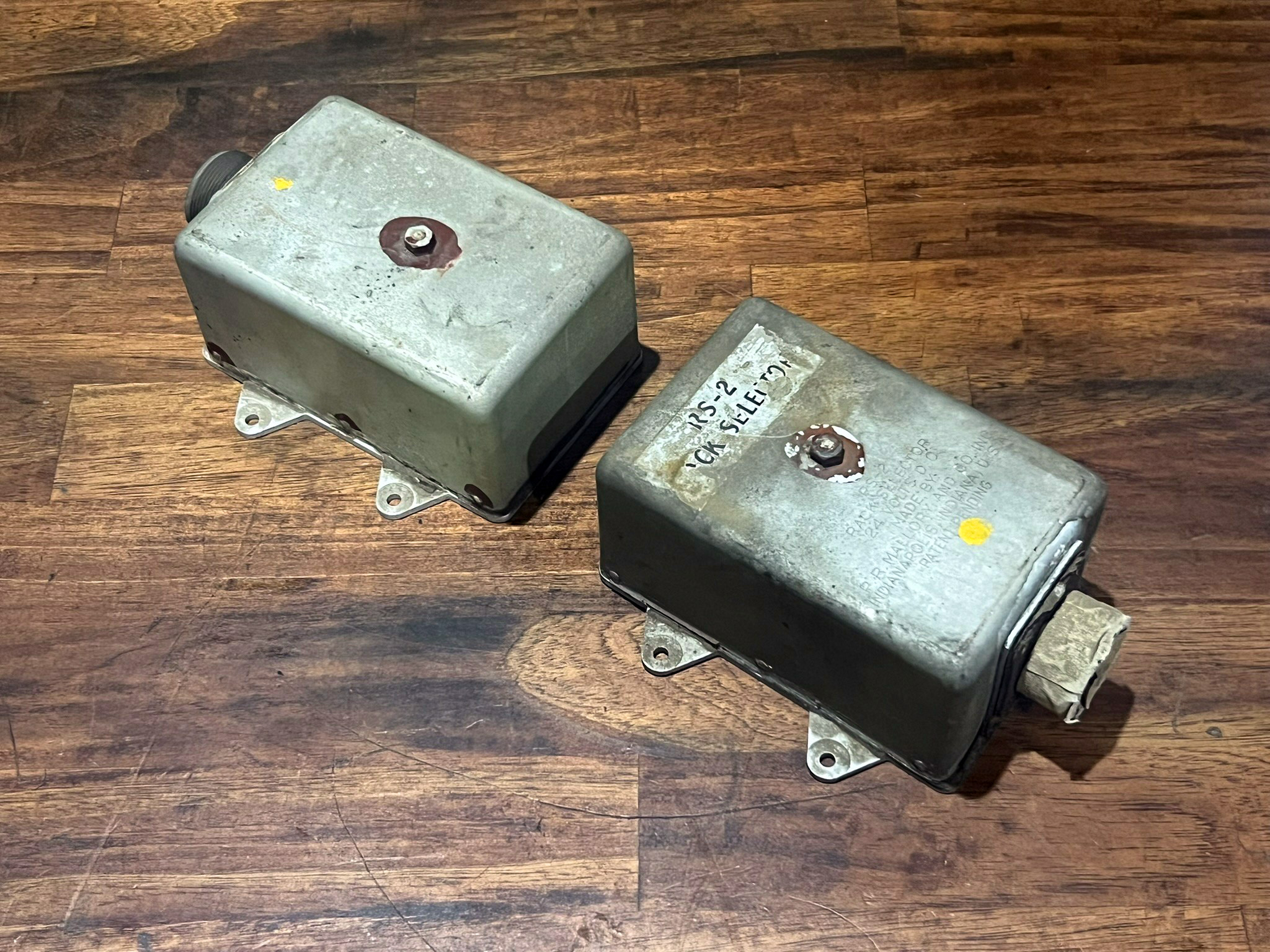
The newly arrived RS-2 relays for Lucky Thirteen.
Photo taken 28 September 2026.
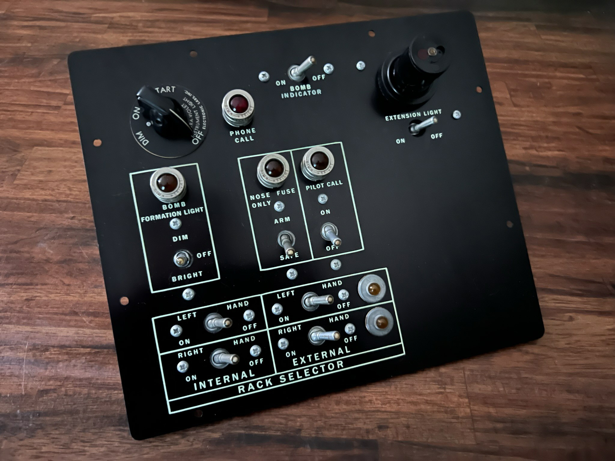
The control panel assembly for Lucky Thirteen‘s bombardier panel. The rack selectors are visible here.
The round object protruding from the upper right is an extension lamp, whose wire spools out when pulled from the panel.
Photo taken 31 July 2023.
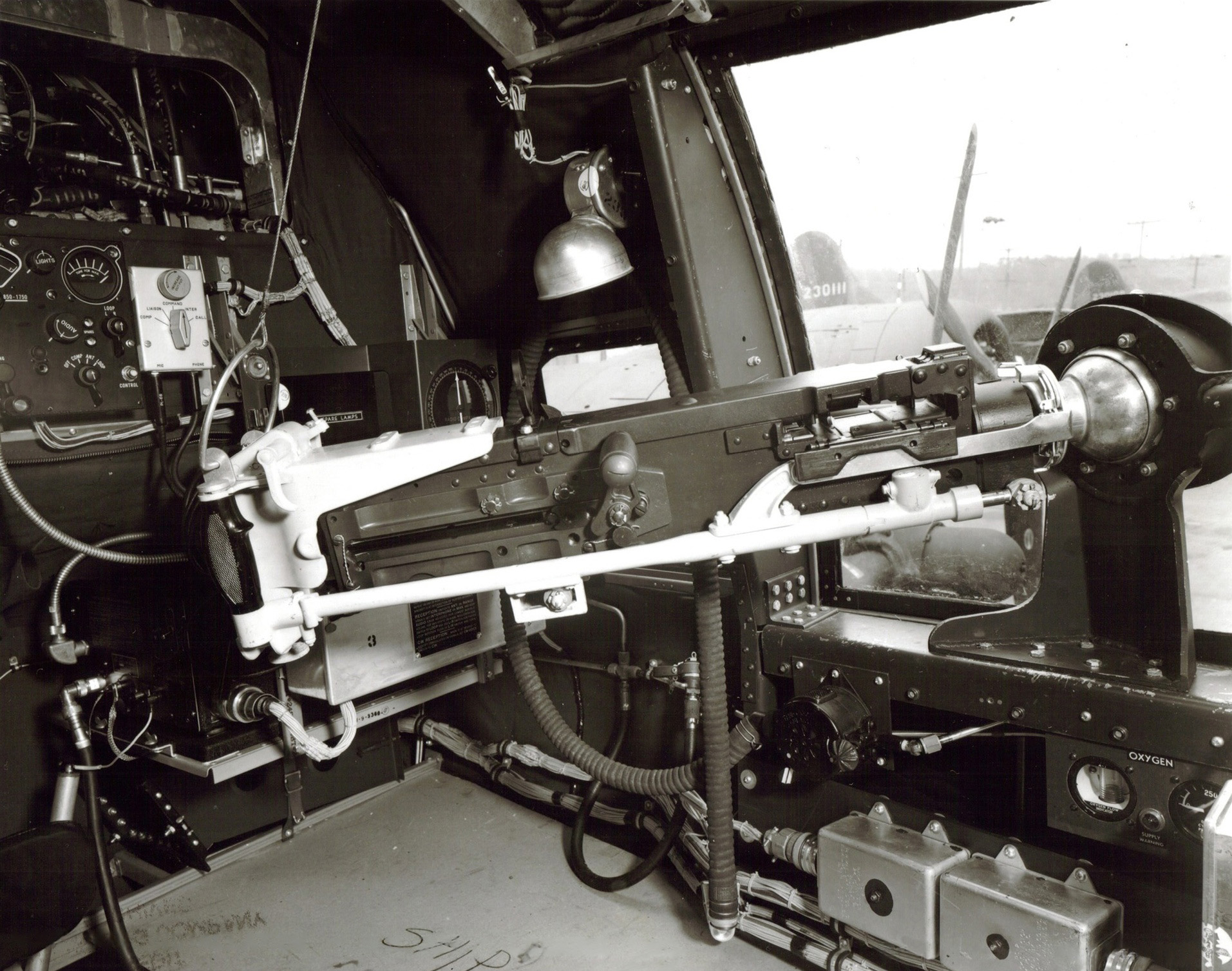
Stateside photo showing the left cheek gun above the navigator’s desk on a B-17F.
The RS-2 relays can be seen under the gun, just below the navigator’s oxygen panel.
Photo taken 9 April 1943.
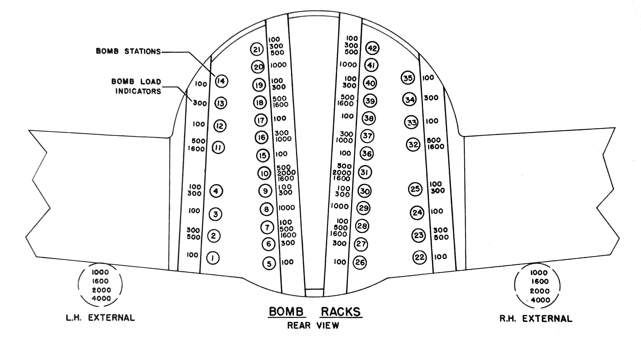
The Boeing B-17 had a total of 42 hard points in its bomb bay, with the option of two additional bombs on the inboard of each wing. Since the external mounts were not limited to spacing between the aircraft’s carry-thru spars, they were intended for oversize bombs.
The B-17’s recommended bombload was 4,000 lbs, with its internal maximum being just over 6,000 lbs – due to operational realities, the latter was more common. However, should it be necessary, including the two external mounts, the absolute maximum was 14,000 lbs. Since weight affects performance (i.e., altitude), this was rarely carried.
The chart shows each hard point, numbered to show the order in which the bombs are released. Beside each number is a note for which size bombs can be mounted at that position.
This piece comes to us from our friend Fred the Turret Guy – it is the post assembly for Lucky Thirteen‘s tail gun.
Longtime followers might recall that our stinger came from 42-30681, a B-17F that served in Alaska with the US 11AF. Her time in Alaska was brief, arriving on 9 September 1943 and being lost to mechanical failure just weeks later. This timeline fits perfectly with Lucky Thirteen, as she was lost on 6 September. Recovered in 2001, virtually all of the tail gun’s accoutrements were removed by others by the time it arrived here in 2022.
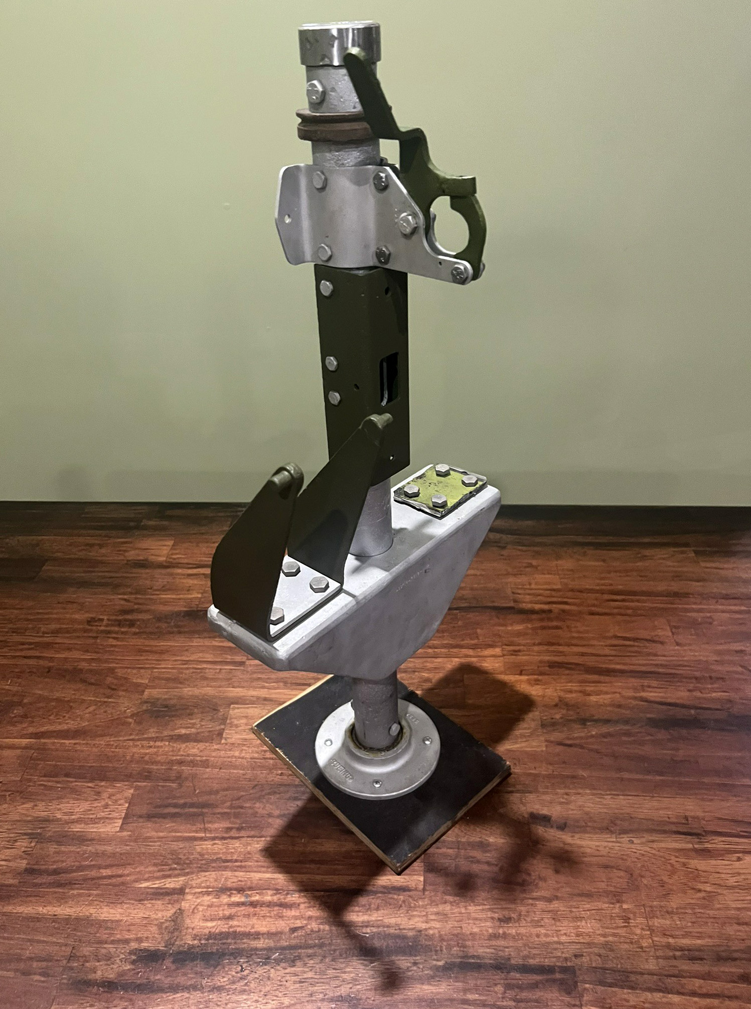
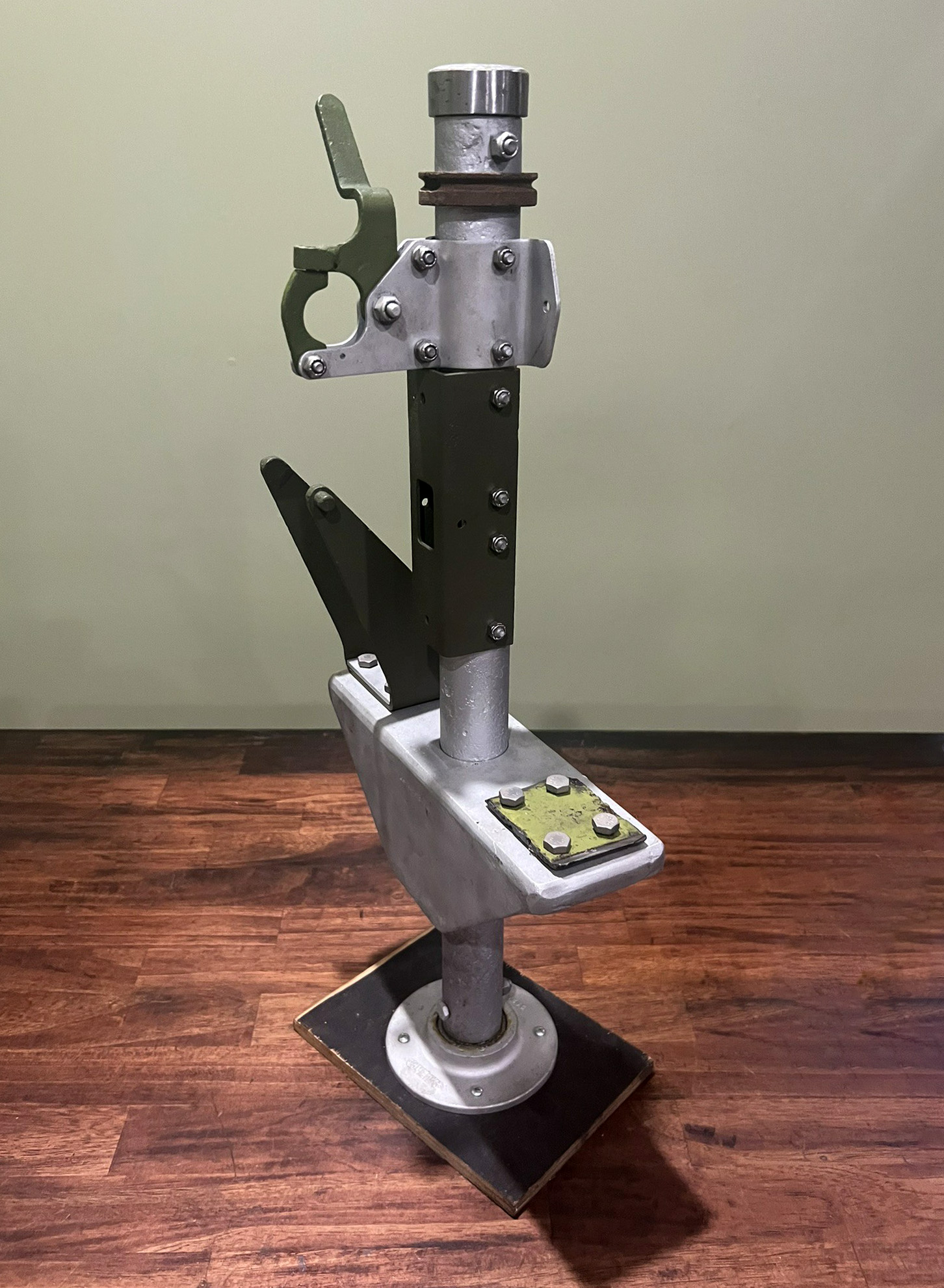
The newly arrived tail gun post assembly. The spring lever is for the ability to attach a tow target.
The two bracket bases suggest that this post saw action, as they are dented from shells ejecting from the Browning .50 caliber machine guns mounted above.
Photos taken 3 October 2026.
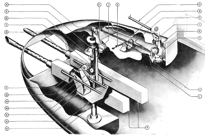
Manual illustration of the stinger-type tail gun post assembly.
Though not illustrated, the tail guns mounted Type E-11 gun cradles to the assembly’s two yokes.
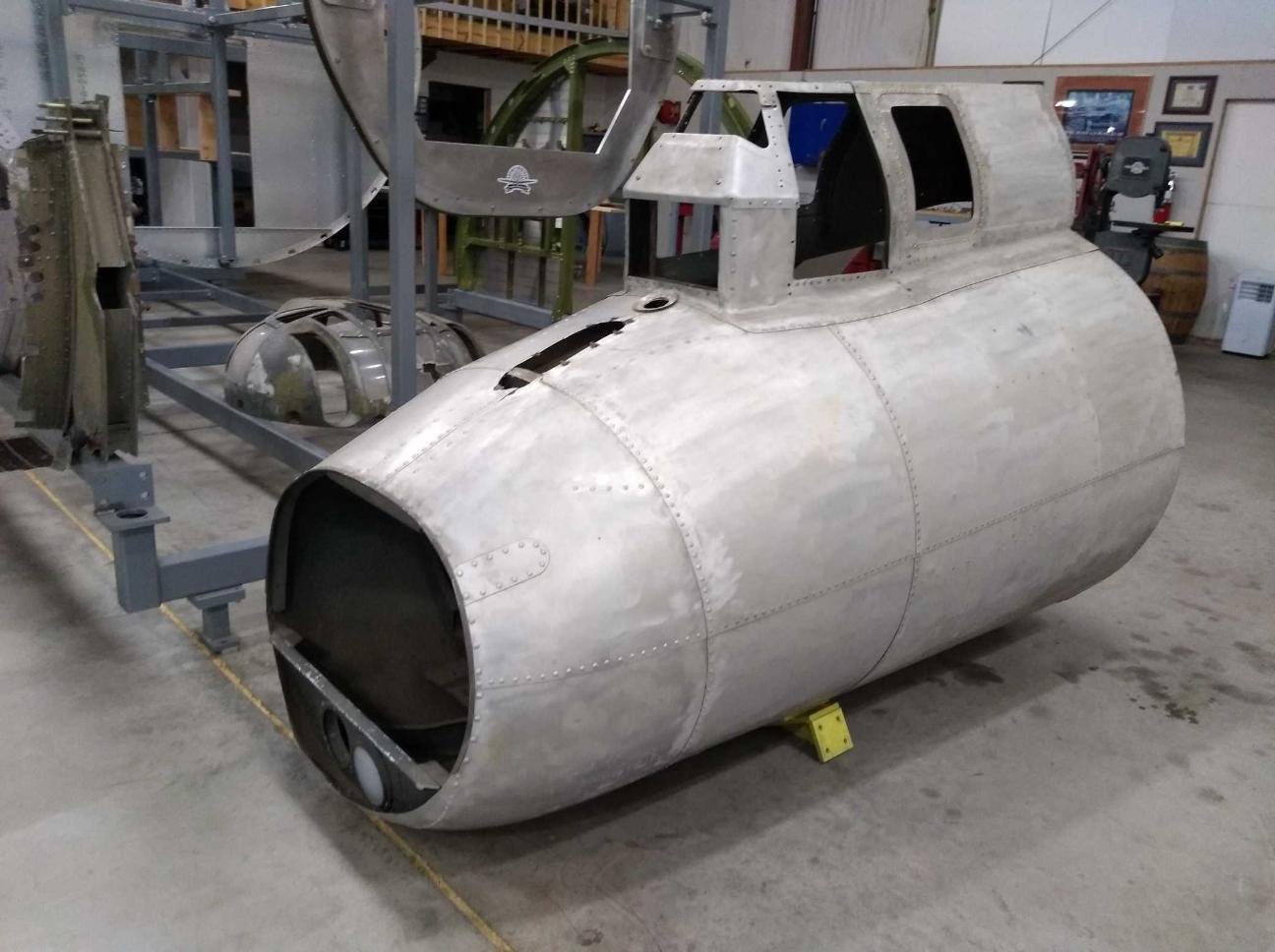
Lucky Thirteen‘s stinger upon arrival.
A patch is visible on the lip of the tail gun assembly. This is wartime original and will be kept as is.
Metal fabricators and machinists are always prized as volunteers and, while we do practice long-distance volunteering, this stinger assembly is the sort of project that awaits those who live local to Asheville and are interested in volunteering.
Photo taken 30 May 2022.
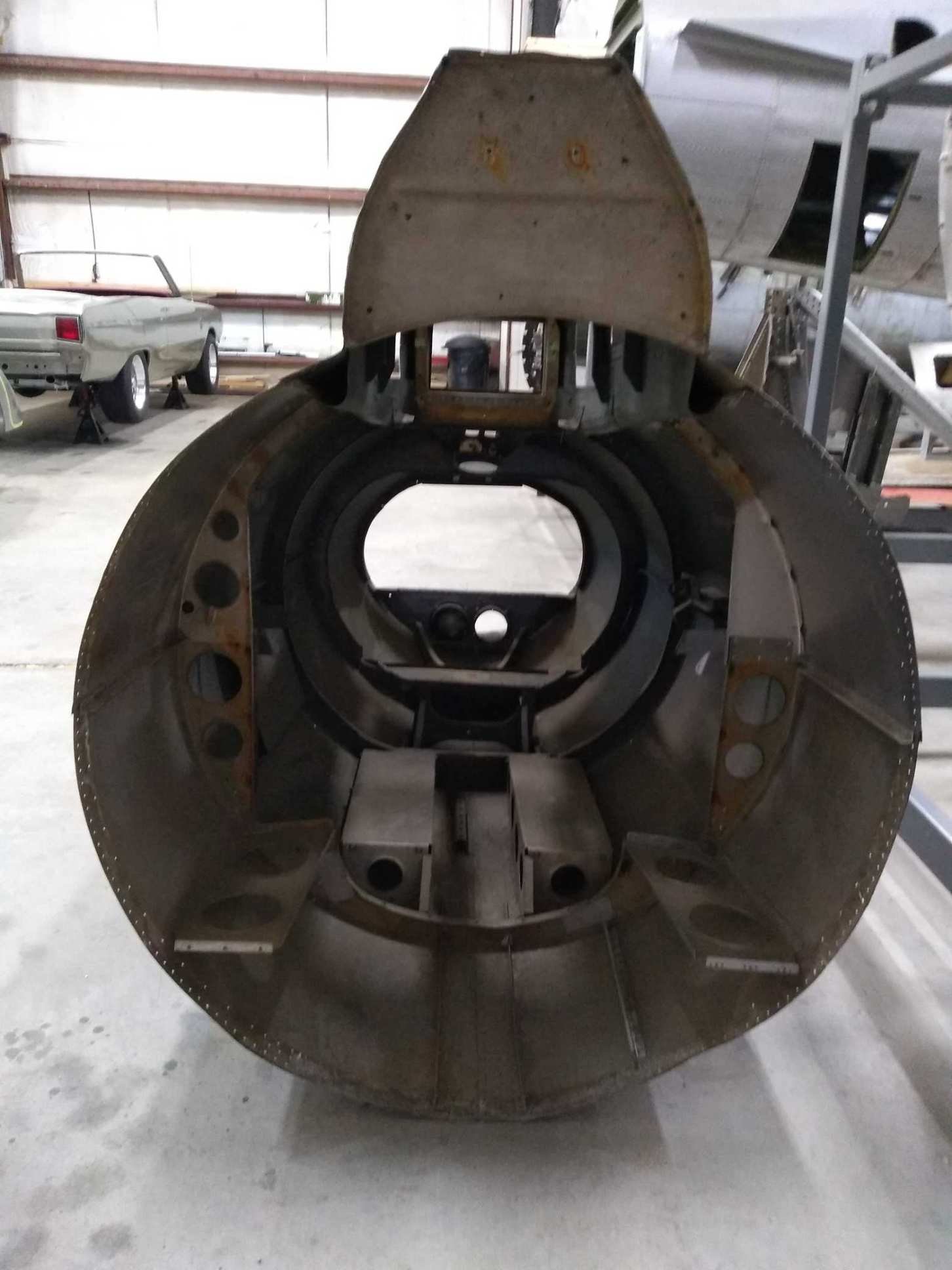

Comparison between the stinger assembly upon arrival versus one in wartime.
While the aircraft’s armor plating was all 1/4″ in thickness, the armor in the tail was slightly thicker at 5/16″. We have vectors prepared for all of Lucky Thirteen‘s armor plate so, providing we can source the ballistic steel, the files are ready to cut them. If anyone can help with this need, please let us know!
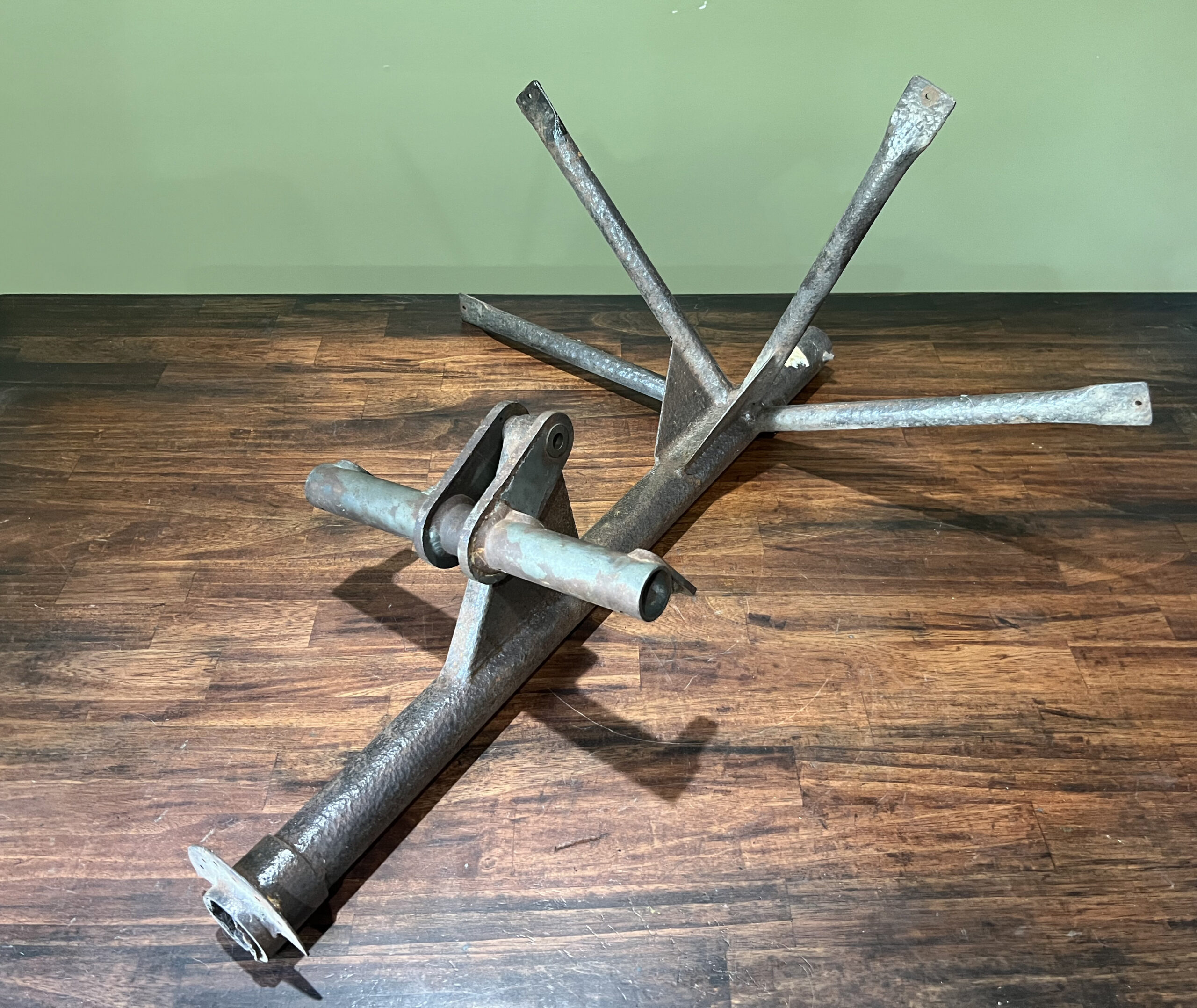
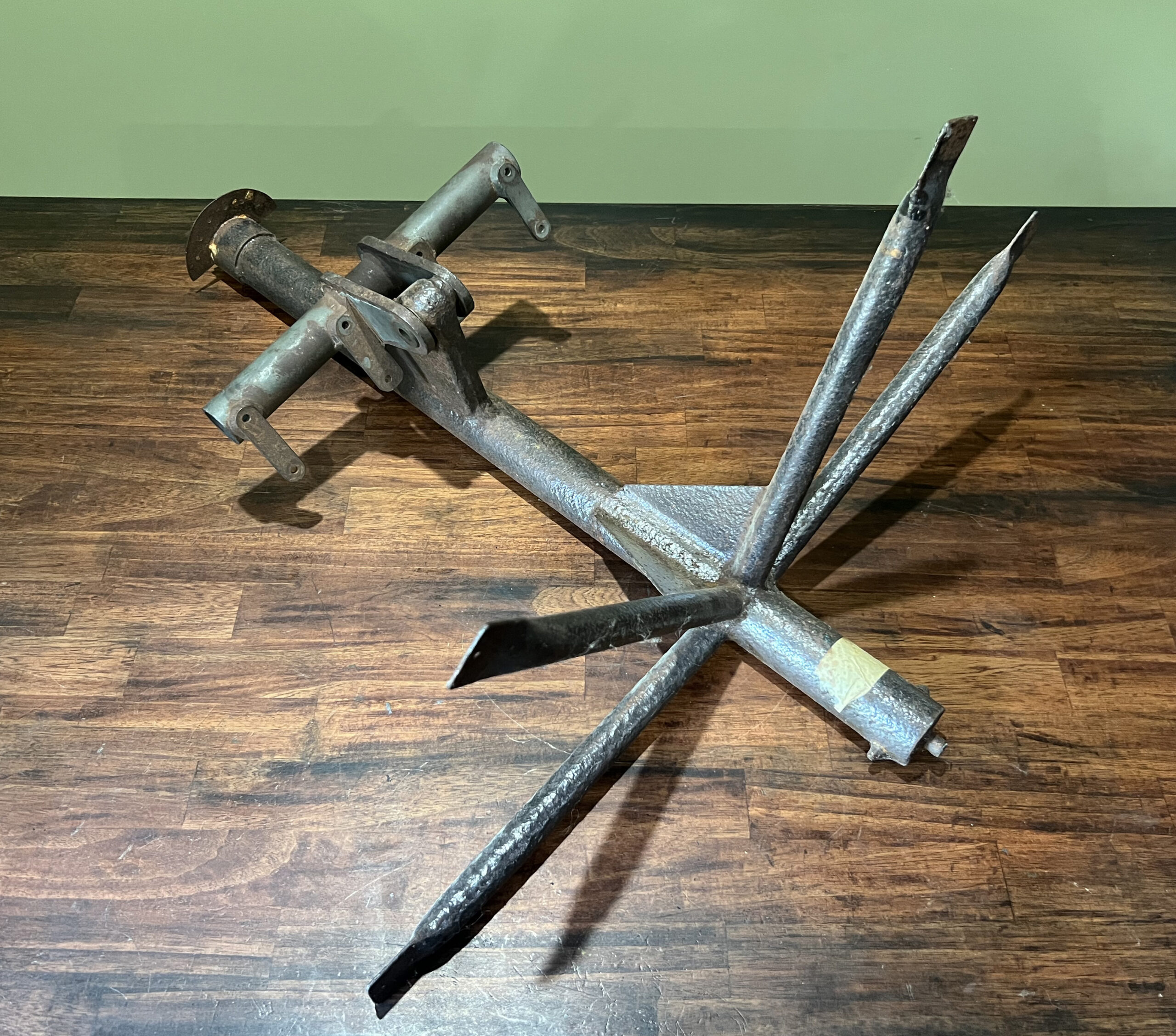
Often our work sees us help with later B-17Gs. This post assembly was taken from a B-17G with a Cheyenne tail gun and loaned to a friend for duplication. These duplicates will soon find themselves displayed both in the United States and United Kingdom.
The smaller piece at the top, which swivels on the main post, is where the E-11 gun cradles were mounted.
Photos taken 4 November 2026.
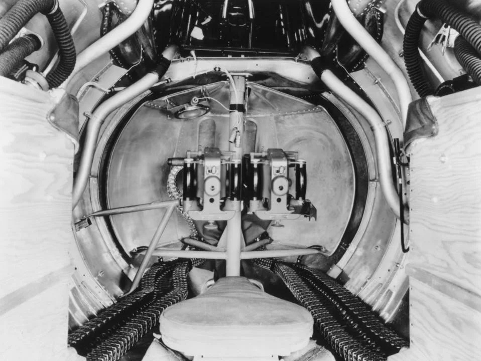
Wartime photo showing the interior of a Cheyenne tail gun position.
This ‘pumpkin’ style tail gave a slightly greater field-of-fire, but most importantly, allowed for the use of a reflector gunsight.
With the Type A-2 Ball Turret’s power assembly restored, attention has shifted toward wiring. This primarily entails the brush assembly which, longtime followers might remember, our example came from the midair collision of Dorsal Queen (42-30264) and Raunchy Wolf (42-3290, 385BG) on 26 September 1943 – twenty days after the loss of Lucky Thirteen.
The brush assembly consists of a phenolic cylinder with a series of copper bands. Copper rods brush against these bands as the turret rotates, transferring power into the ball below. On the A-2, from top to bottom, these bands cover the Ground, two Microphone lines, two Headset lines, two Spare lines, and Main Power.
Because of electromagnetic interference brought on by the drive motor, reception on the A-2’s communications equipment was not great. Subsequent turret variants featured a noise filter, prominently mounted on the hanger assembly.
Taking this A-2 brush cylinder apart, we found something unexpected. One of the microphone lines had been replaced with a shielded wire, furthermore having a braided line bridging it to one of the turret’s two ground lines. We have no idea if this was a field modification or something done at the Briggs factory. However, it does show that someone, somewhere, was working on the problem of electromagnetic interference on the A-2 prior to the introduction of the A-2A.
Special thanks to Michael Cook and Fred Bieser for their help on researching the ball turret brush assembly.
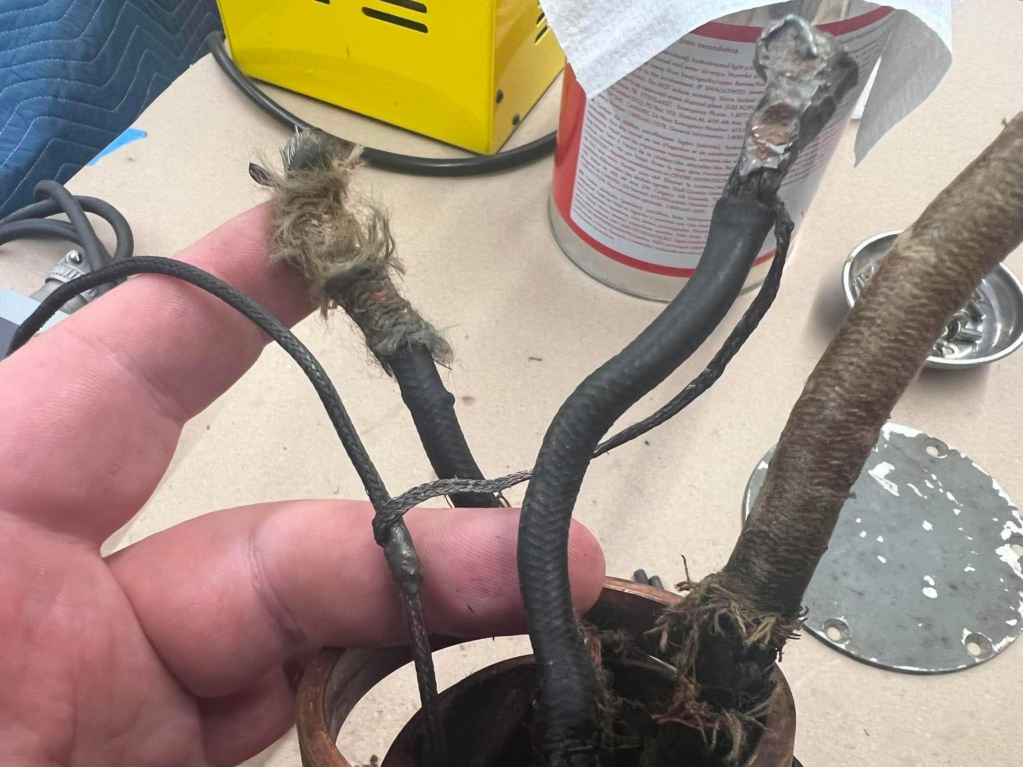
The shielded wire (left) and its bridge to one of the turret’s two ground wires.
Photo taken 31 August 2026.
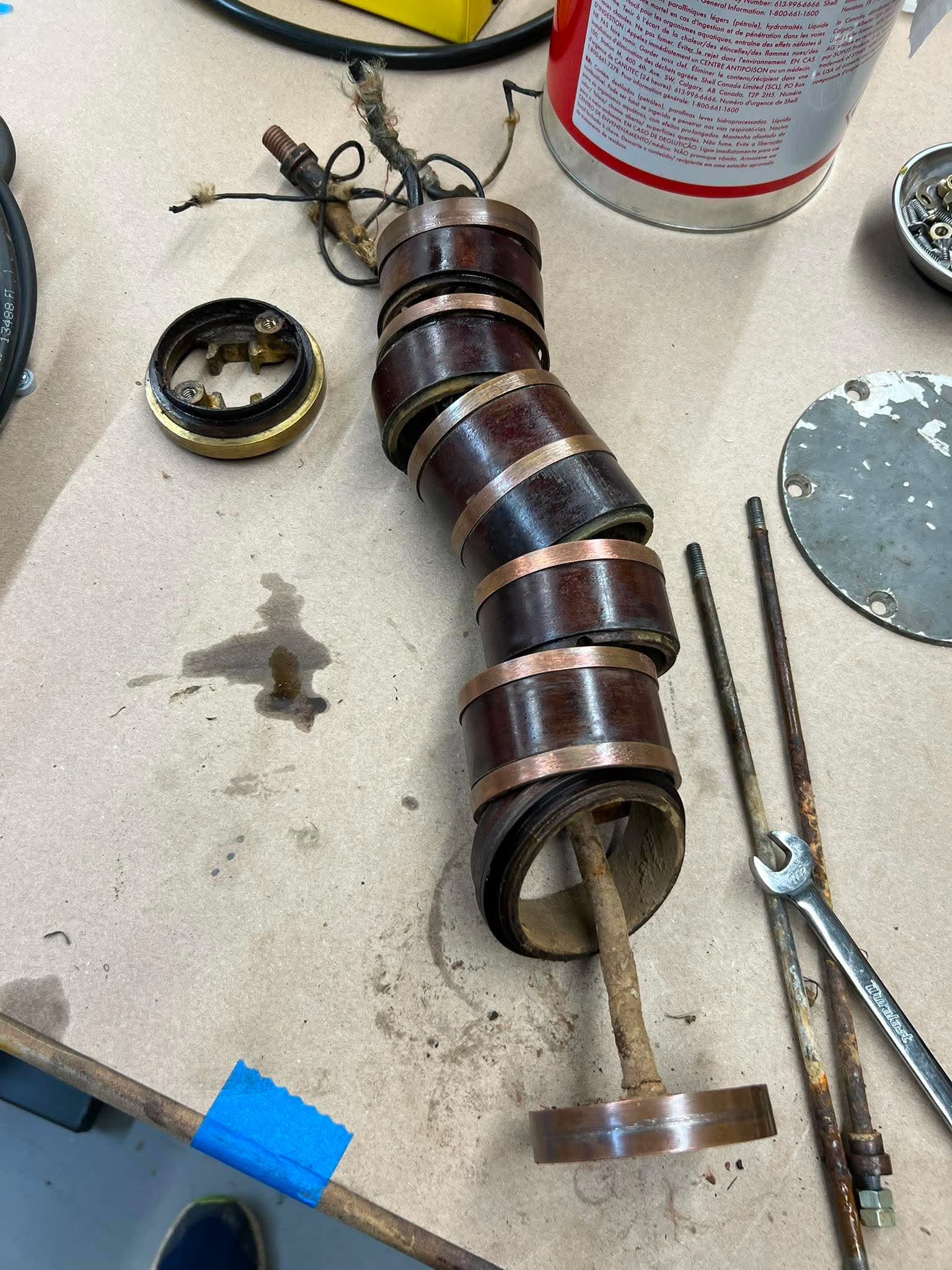
The phenolic cylinder for the brush assembly is slowly disassembled so that it can be rewired to run again.
Photo taken 31 August 2026.
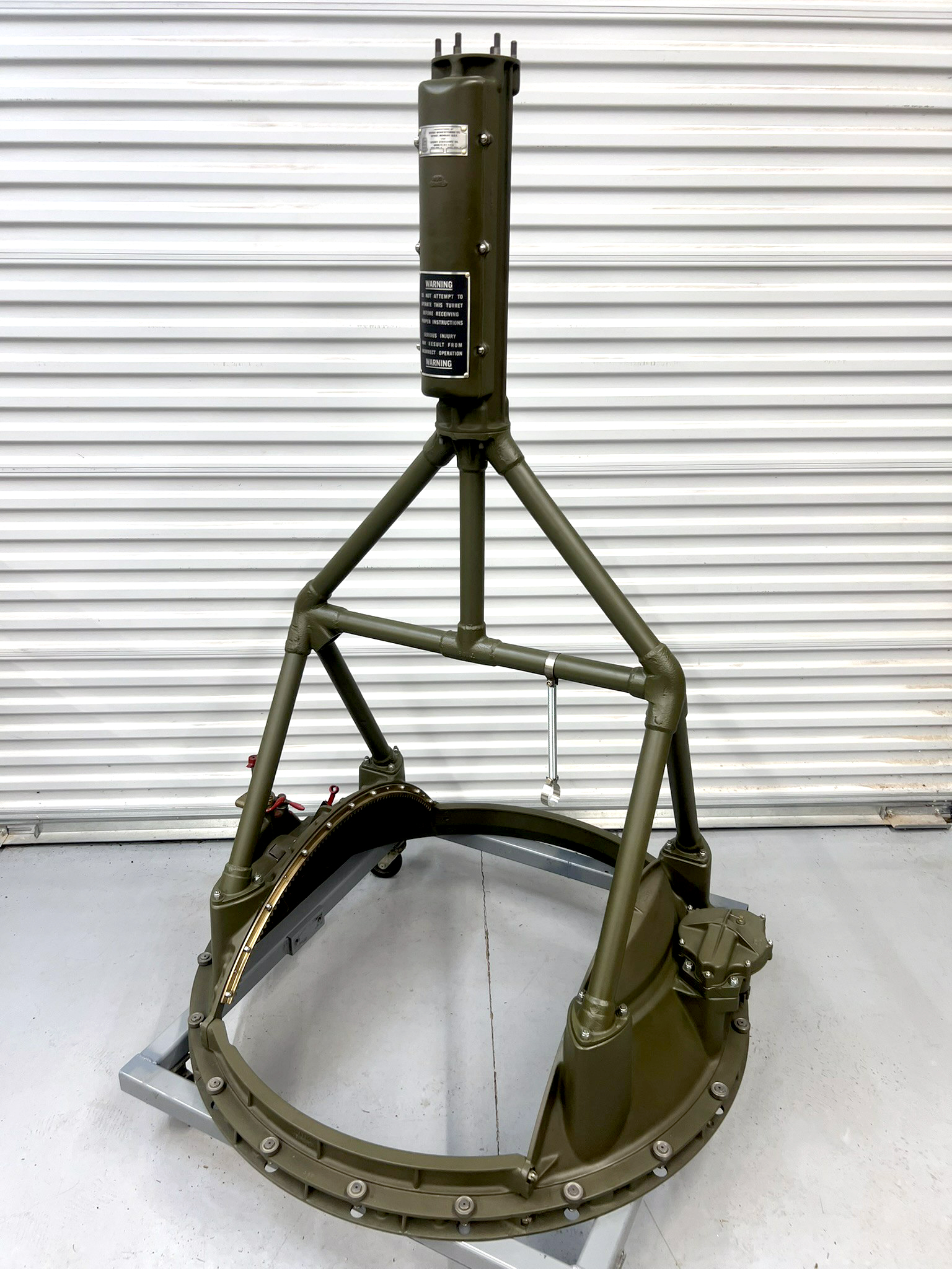
The restored hanger and trunnion assembly for the Type A-2 Ball Turret on Lucky Thirteen.
The brush cylinder was housed in the large piece at the top.
Photo taken 26 February 2026.
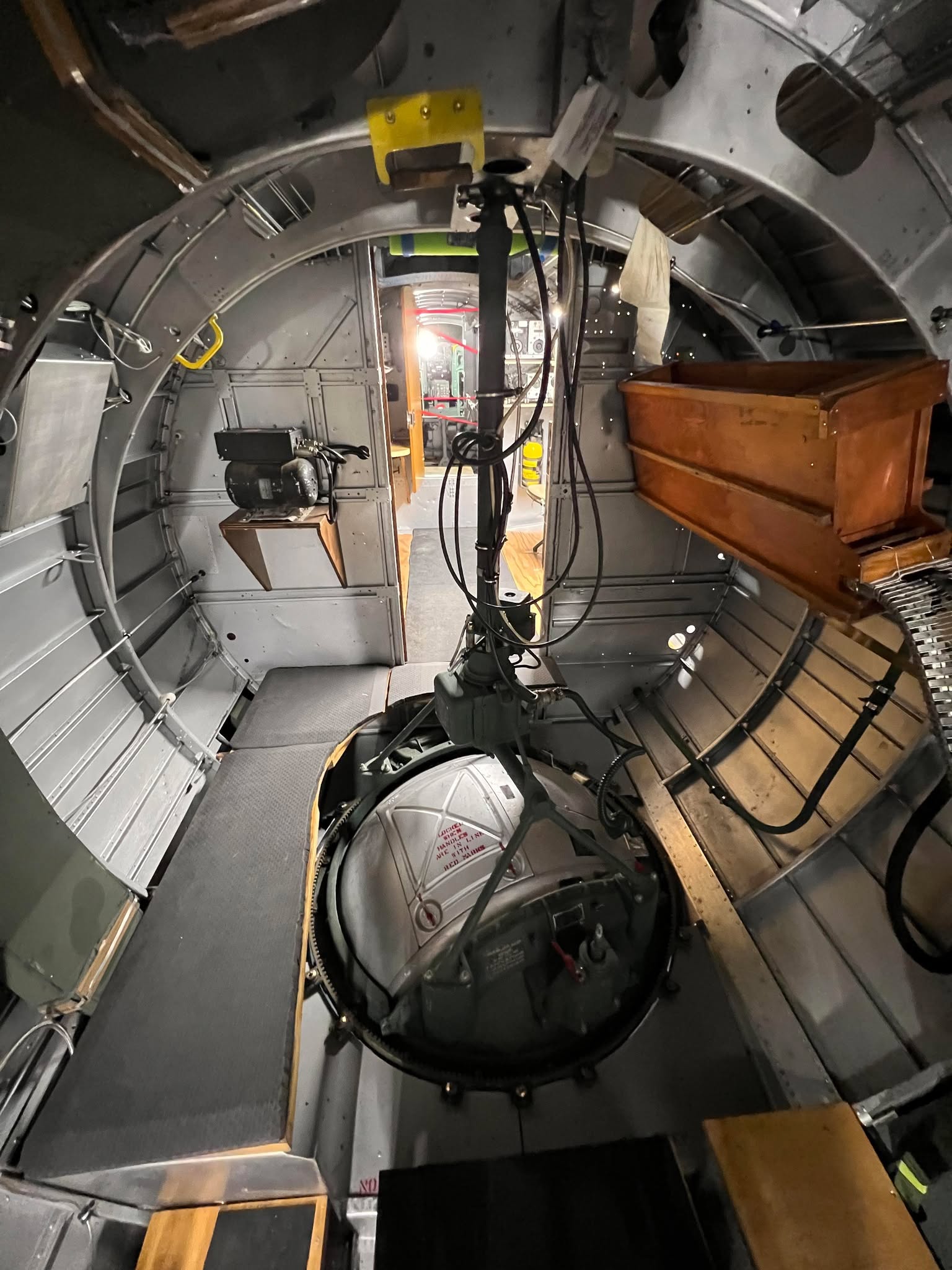
The ball turret aboard 44-83690 at the Museum of Aviation in Warner-Robins, Georgia.
The hanger assembly on this turret is from an A-2A. The small box with the dimple on top is the noise filter.
Photo taken 18 August 2023.
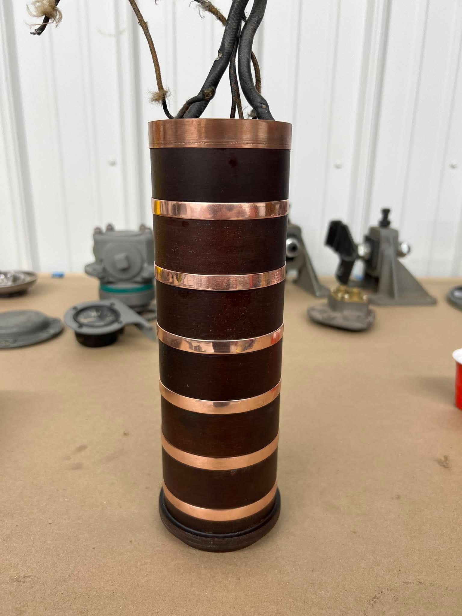
The bands on the A-2’s brush cylinder are cleaned and polished, after being exposed to the elements for the past 80 years.
Photo taken 18 October 2026.
Speaking of the brush assembly –
The brush rods on our example were all either broken or badly damaged from the midair collision, so replacements needed to be machined. Originals were loaned to our friends at the Planes of Fame Museum in Chino, California, where they meticulously recreated a set for Lucky Thirteen. These were machined by Dietrich Kanzler, the machinist for the museum’s B-17 restoration group.
Dietrich’s work is absolutely gorgeous.
The brush rods came in two sizes, the larger of which were used for main power and the turret’s grounding. The smaller rods were used for the turret’s headset, microphone, and spare lines. An additional pair of each size were kept in the turret’s spare parts box.
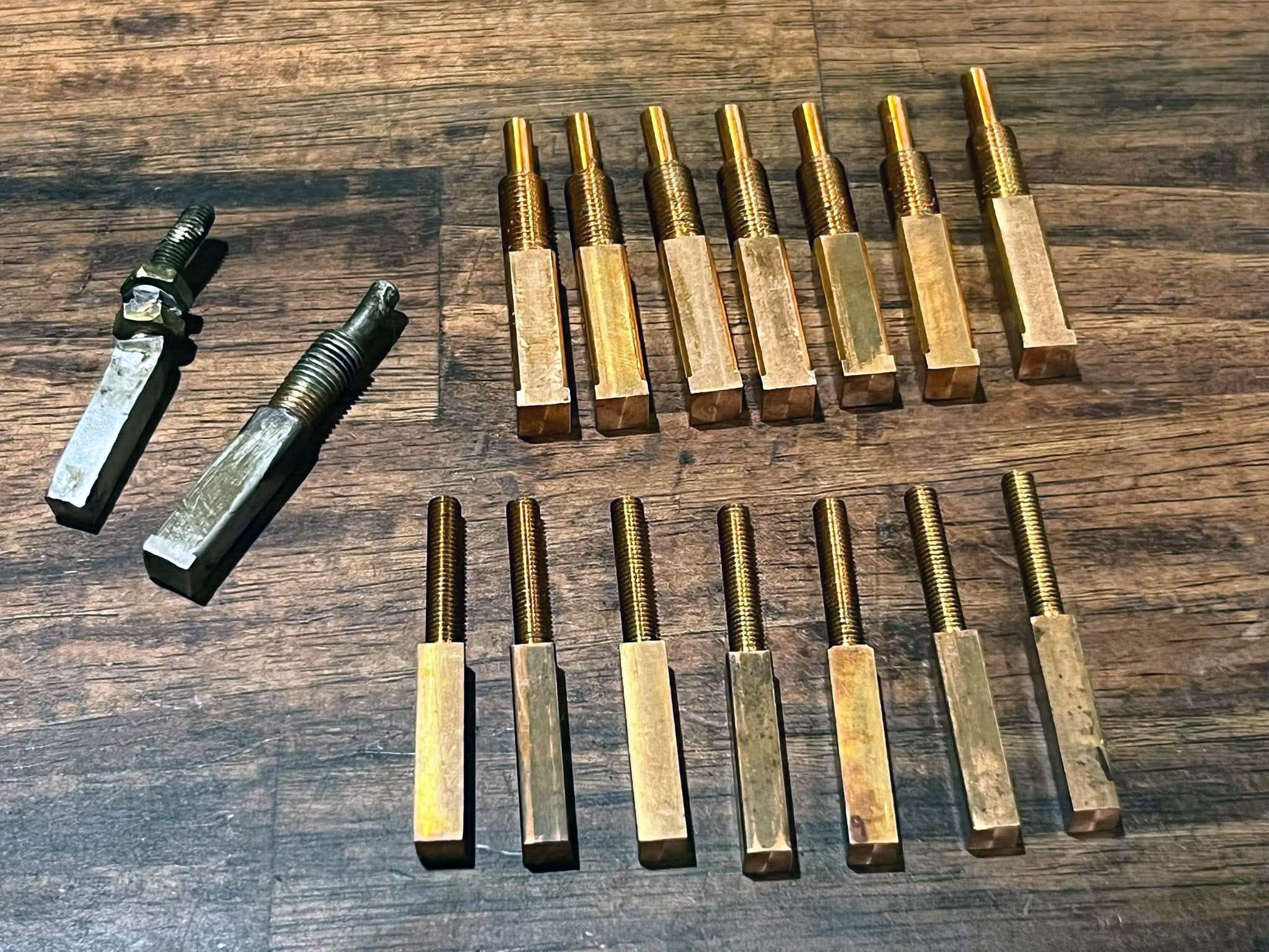
The newly recreated copper brush rods for Lucky Thirteen‘s Type A-2 Ball Turret.
Photo taken 3 October 2026.
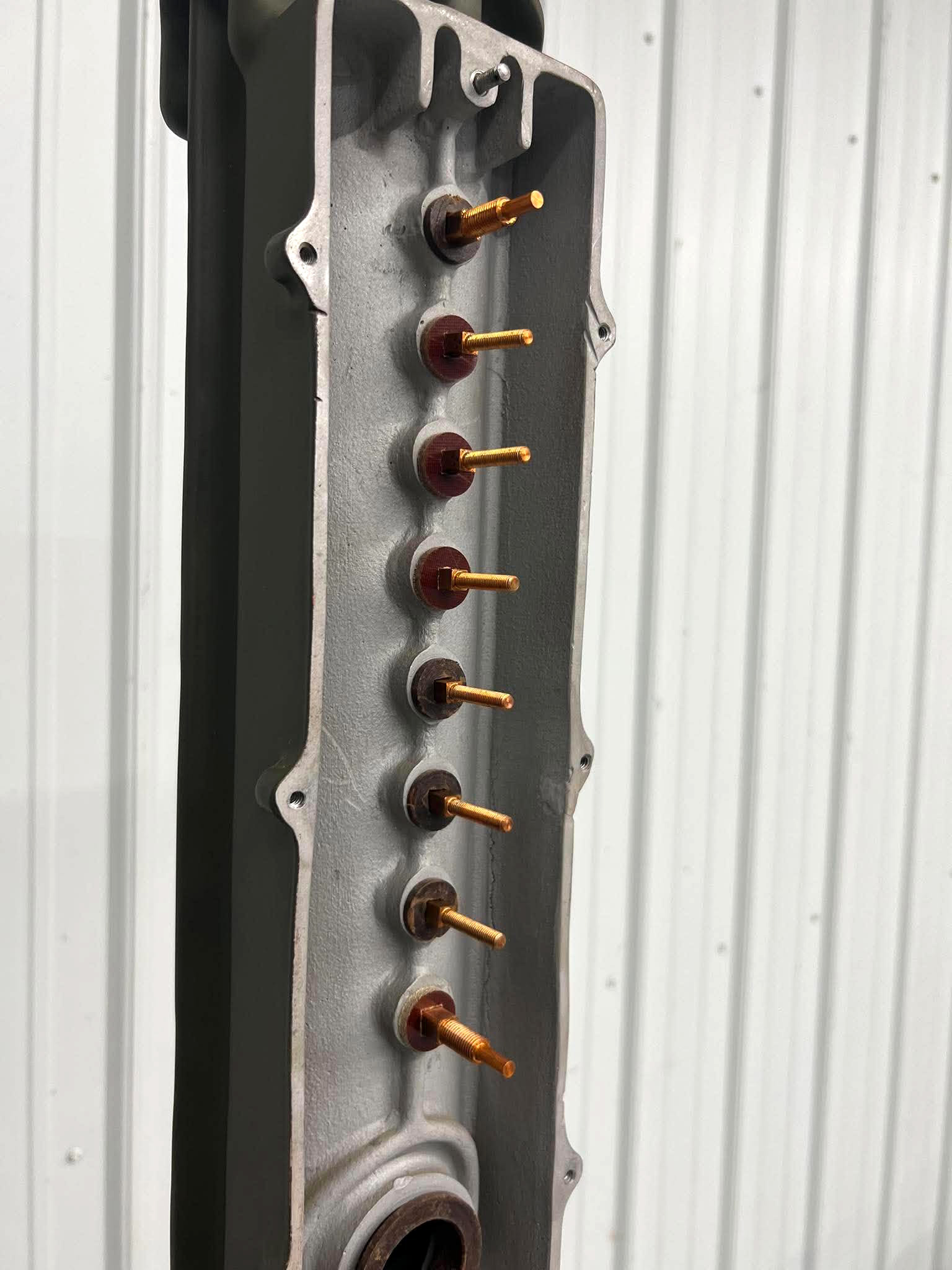
The copper brush rods in the restored brush housing. Four of the phenolic sleeves had to be replaced, while the other four are wartime original.
From top to bottom: ground, the two microphone lines, two headphone lines, two spares, and main power.
The lines from the plug on the hanger assembly come up the pipe and out through the large hole at the bottom here. Each wire terminates with a lug bolted to a brush rod.
Photo taken 4 October 2026.
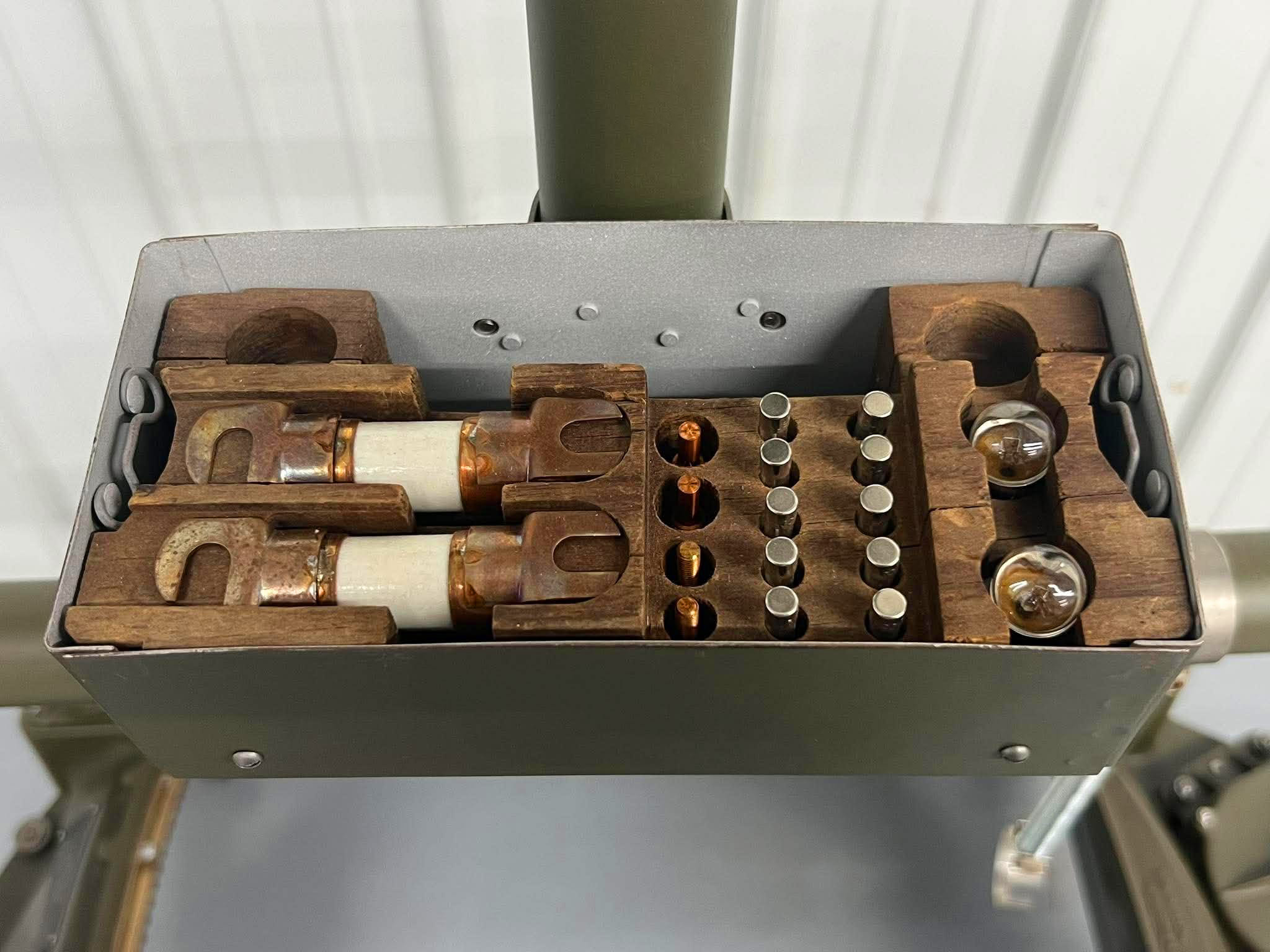
Progress in filling out the Spare Parts Box on Lucky Thirteen‘s Type A-2 Ball Turret.
Alongside the newly machined brush rods, two spare 120 amp 28V DC fuses have been located. All that remains are the turret’s door check wires and two spare slip ring retainers.
Photo taken 4 October 2026.
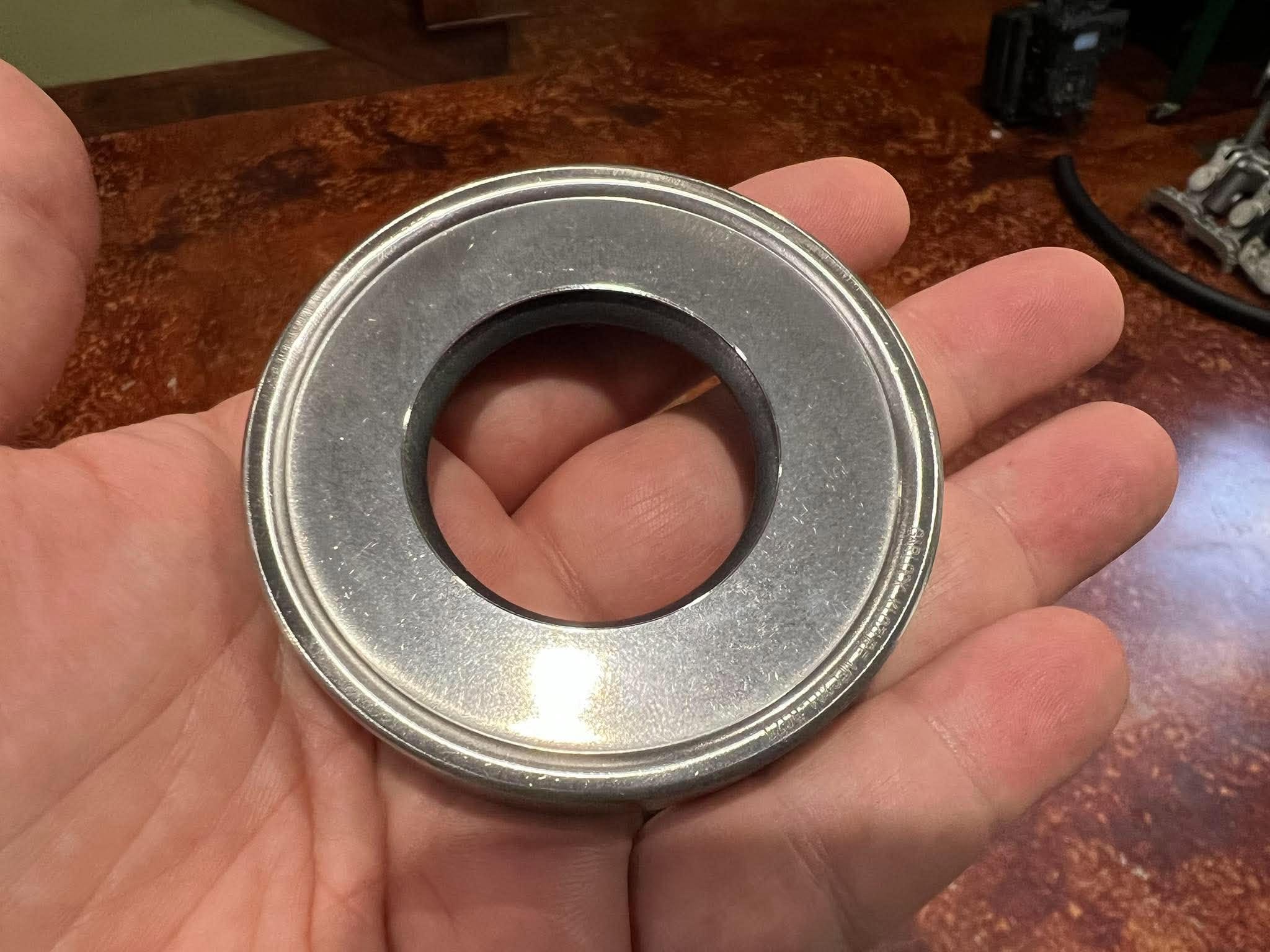
Another recent arrival for the ball: the Garlock seal for the turret’s main bearing.
This seal was custom made by Garlock for the project, as it has not been produced since the war. It took some time to come through, but the wait was worth it.
Photo taken 2 October 2026.
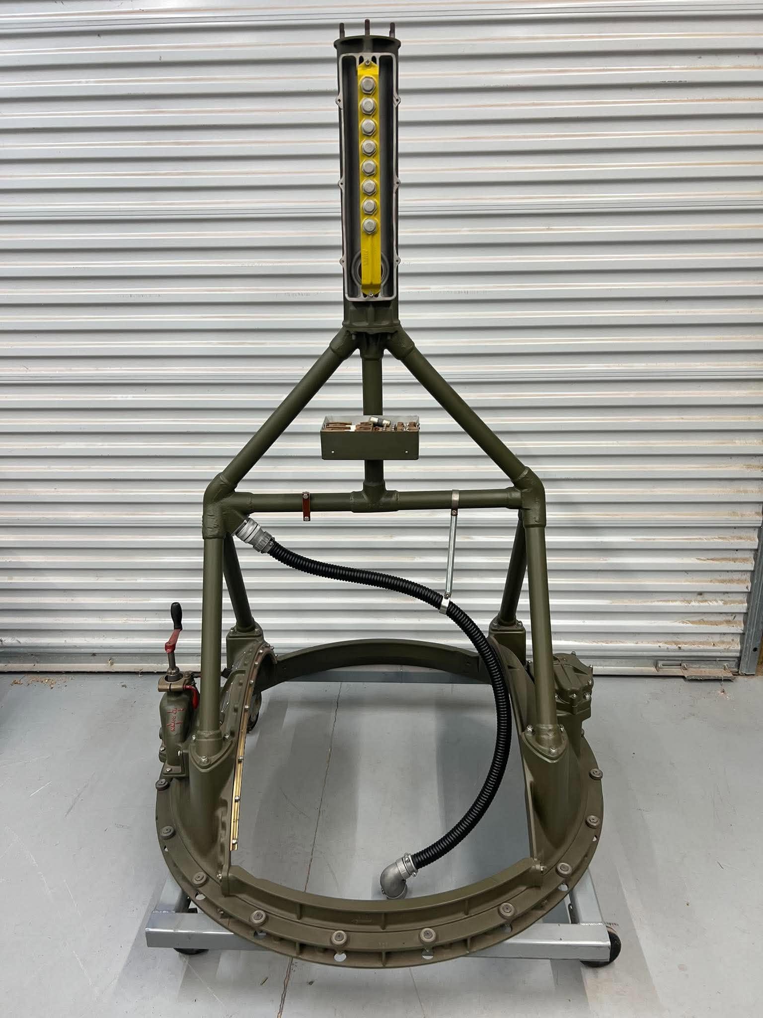
As mentioned in our previous update, the Kanaflex Corporation of Vernon Hills, Illinois generously donated the proper hose for the turret’s main power conduit. We just had to attach the main power line, even if it has not yet been wired!
To complete this conduit, we will have to track down replacement power plugs. These are two 3106-32-3Ps, a 3108-32-3S, and a 3100-32-3P connector, the last being a modern approximation of a type no longer made. Newark is the traditional distributor for such things but, for whatever reason, they do not sell the aforementioned connectors in the US. So, we will have to order them through a middleman once funds are available. Based on prior experience, it will likely take many, many months for said connectors to arrive once ordered.
The wiring inside these conduits cannot be completed until said connectors are here. In the meantime, empty wartime shells make for nice placeholders.
Photo taken 17 October 2026.
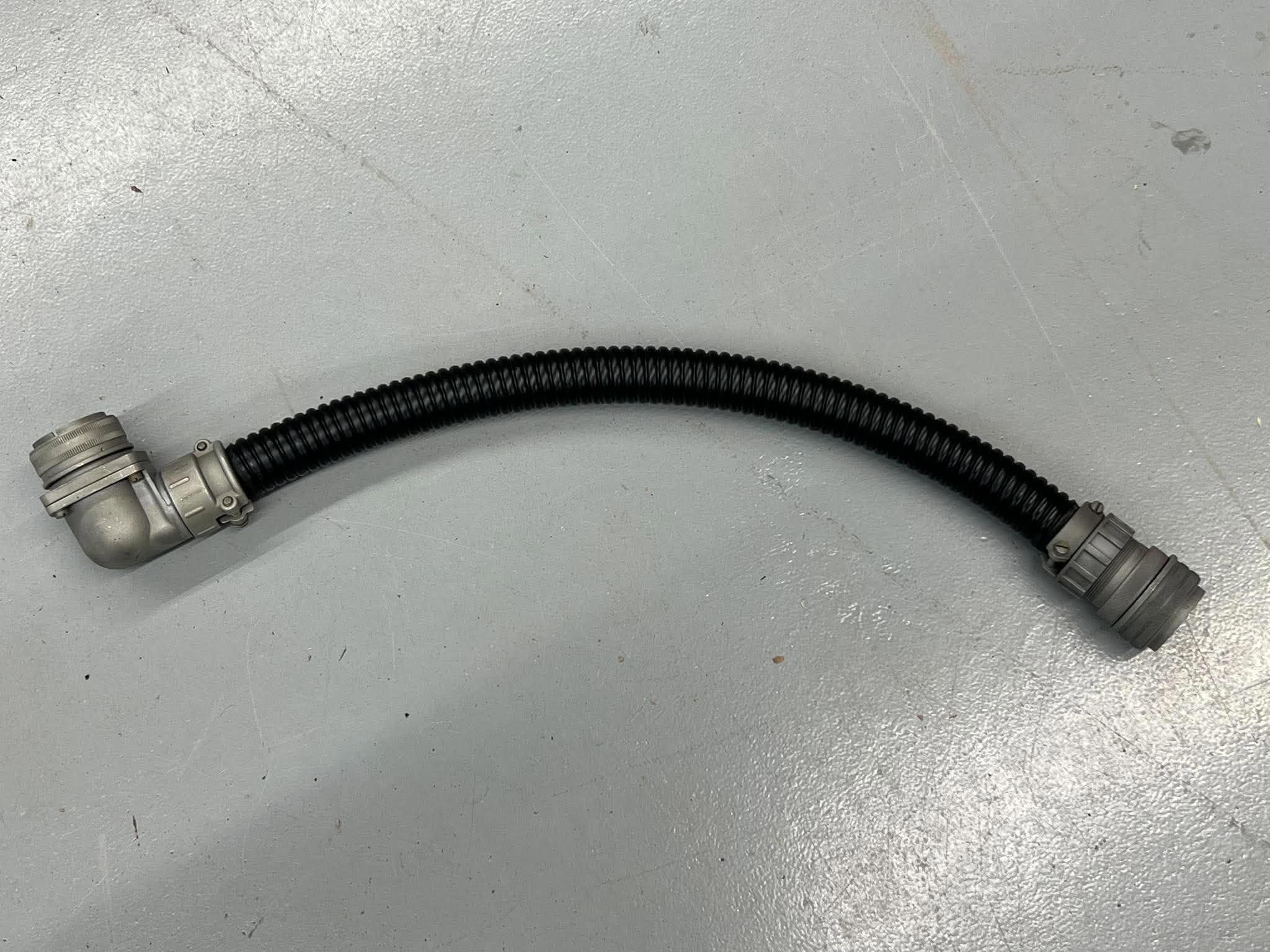
The inner conduit, mocked up with empty wartime shells.
The shell on the left is a type no longer made today. Period connectors used tension rings to hold the rubber inserts inside. If that were still the practice, it would simply be a matter of installing the correct pin-arrangement insert. Sadly, that is no longer the case. A modern equivalent has been chosen in the hopes that it can be made to either work on its own, or possibly mate with the shell seen here.
Photo taken 17 October 2026.
Next, we have an incredible donation from our friend Scott Burner. Scott is the grandson of TSGT Leonard Nealis, flight engineer/top turret gunner on Little America (42-30033, 384BG). The original co-pilot on Little America was 1LT Russell Faulkiner, who went on to become the pilot of Lucky Thirteen. In fact, they were good friends and Nealis witnessed Lucky Thirteen drop out of formation on her last mission; seeing Faulkiner’s safe return months later was a much-welcomed shock.
The Burner family are some of our closest friends and are truly wonderful people. And this donation was certainly a much-welcomed shock: Scott donated an original rain cover for the Type A-1 Upper Turret.
The Type A-1 Upper Turret went through several dome variants between the two A-1 manufacturers: SPECO of Ohio and Emerson Electric of Missouri. Of the two, SPECO built slower, being somewhat hands-on in construction, whereas Emerson built on an assembly line. As such, SPECO turret’s changed dome designs regularly throughout the war. Emerson only changed domes once. This is one of the ways you can spot an Emerson-built turret in wartime photos – later-Fs with early style domes had Emersons.
The Type 1 and Type 2 domes were identical, each being the first dome made by the two companies. As such, while this particular cover is dated 1942, it is still appropriate to the A-1 on Lucky Thirteen. And it fits the dome perfectly!
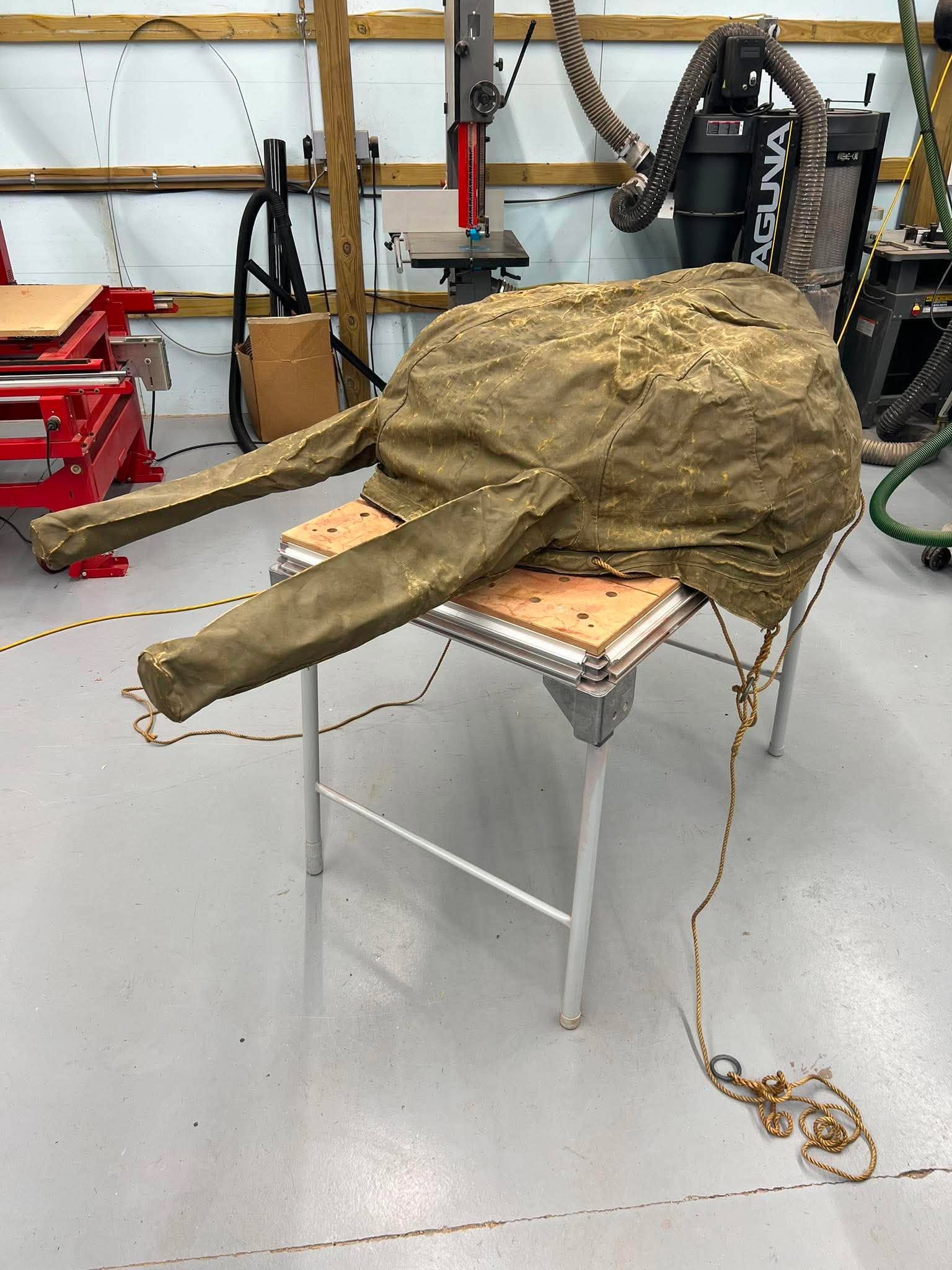
The top turret rain cover atop the Type 2 dome.
Photo taken 2 September 2026.
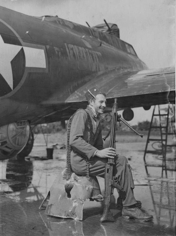
SSGT Elmer Leonard of the 390BG poses with souvenirs he brought back from North Africa after the Schweinfurt-Regensburg strike. Lucky Thirteen and Little America were both veterans of this operation.
Note the rain cover on the upper turret.
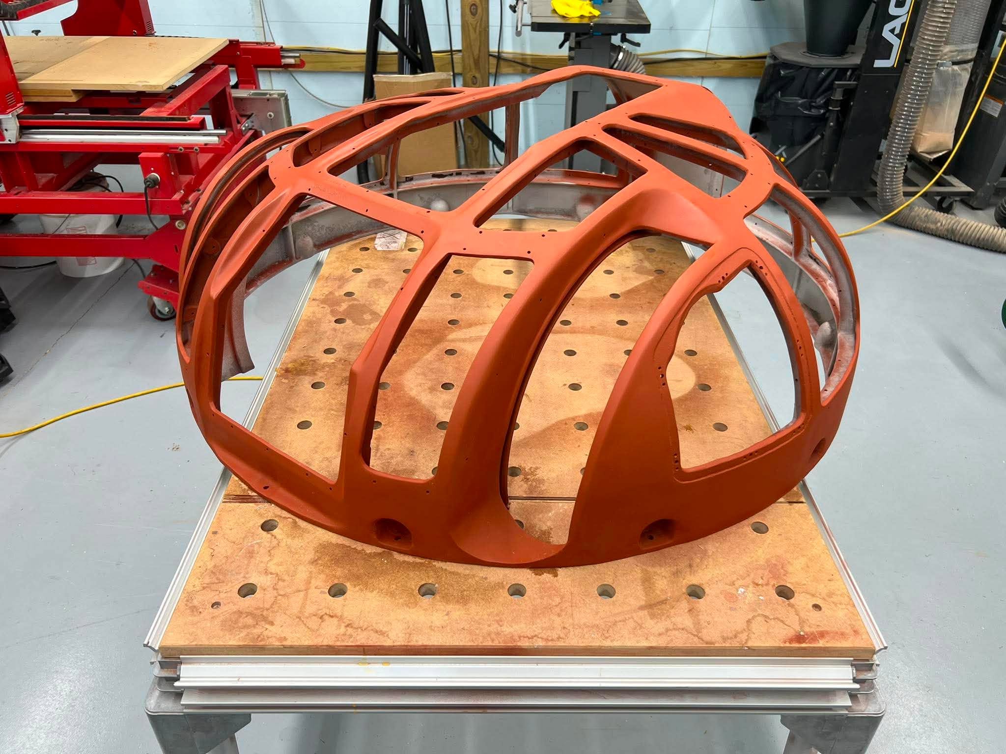
Progress on cleaning up the Type 2 upper turret dome. The replaced broken pieces are now seamless.
A red primer is used to help get the best possible finish. When ready, the proper wartime yellow primer will be applied.
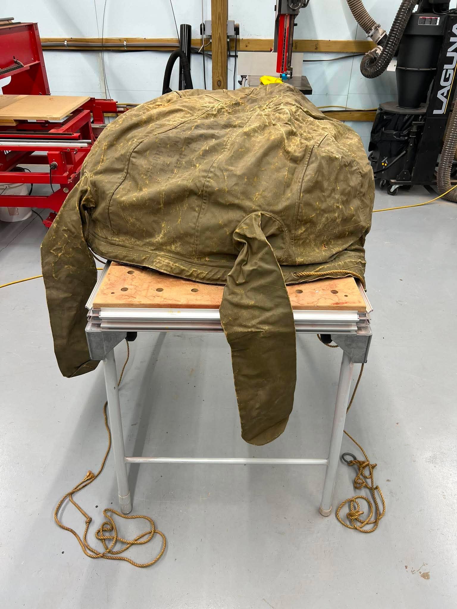
The top turret rain cover atop the Type 2 dome. It looks sadder without gun barrels…
Photo taken 2 September 2026.
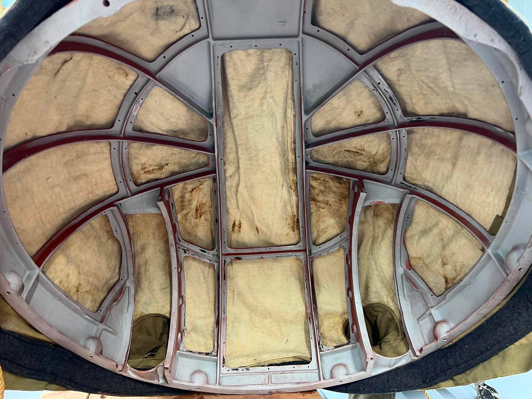
The inside view of the top turret rain cover. The stitching on the cover perfectly aligns with the bars on the dome’s windows.
Photo taken 2 September 2026.
The Hangar Thirteen Foundation is a 501c3 nonprofit charity dedicated to bringing back a B-17F representative of the bloody counter-air campaign of June 1943 through March 1944. Donations to this project are tax deductible. If you can spare a little to help this project, you can guarantee that you will see the results on Facebook and here on our website.
You can contribute through the Donate page or, to avoid a PayPal fee, you can send something via the mail to:
Gerad Allen Blume
Hangar Thirteen Foundation
442 Old Chalk Bed Road
Batesburg, SC 29006
Volunteers are also always welcome. In fact, you need not be an Asheville resident – you can work from home! Persons skilled with metal fabrication, machining, CAD modeling, metal casting, 3D scanning, and laser/waterjet cutting, are particularly helpful. Just reach out to us to get started.
Keep the show on the road!