
The Boeing B-17 is legendary for its role in the creation of the pilots’ checklist.
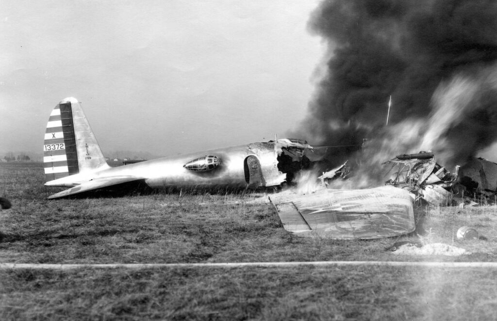
In the early years of the Great Depression, Boeing struggled to compete with Douglas, whose DC-3 airliner managed to keep the company from going under. While the Model 299 (the prototype for the B-17) had to be built with borrowed cash, Boeing managed to surpass expectations with the new bomber. Flying from Seattle, Washington to Dayton, Ohio for service trials, the 299 shocked the world by completing the journey in 9 hours, 3 minutes, at an average cruising speed of 252 miles per hour. Yet despite this accomplishment, Army test pilots MAJ P. Peter Hill and 1LT Donald Putt crashed the bomber on 30 October 1935 – just two months after its first flight – killing everyone aboard.
Subsequent investigations discovered that the pilots had forgotten to release all of the aircraft’s control locks. A minor mistake which, in the end, cost the lives of five people.
Following this discovery, regulations were introduced which required not only Army pilots be trained on new aircraft by factory test pilots prior to flight, but that all flight crews – civilian and military – follow mandatory checklists for start-up, take-off, landing, and shut-down. These rules are still with us today.
Boeing lost the contract and the War Department selected its competitor, the Douglas B-18, as its new primary bomber. Air Corps leaders, who favored the B-17, were able to sustain Boeing by purchasing the maximum number of aircraft allowable for service testing: 13 bombers. This was the number of B-17s the United States had on hand when Germany invaded Poland in 1939.
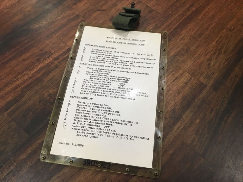
The Boeing B-17’s checklist was kept in a plastic sleeve clipped to the co-pilot’s right side. Hangar Thirteen recreated a pair of checklists for Lucky Thirteen and Memphis Belle back in 2020, both of which were kept in wartime sleeves. These checklists were based on those used on early F-model B-17s and it is likely that Lucky Thirteen‘s checklist was originally a latter variant printed with fluorescent ink on black cardstock. However, we have yet to find an example of late-F checklist, either original or for reference in creating new examples.
There are commercial replicas available based on the checklists used by the B-17G (whose header notes its applicability to late-B-17Fs), but these are not accurate to our serial. If you should have access to a checklist from a late-F, please let us know!
This amplified checklist (an expanded version of the aircraft’s onboard checklist) was transcribed from a wartime original donated to us by our friend Howard Lawson of Jacksonville, Florida. If you find any errors in our transcription, please let us know!
B-17F AMPLIFIED CHECK LIST
Introduction
The number of controls necessary for the operation of an airplane the size of the B-17F make it essential that check lists be used. Even the most experienced pilots on this airplane cannot consistently remember all the things that must be done for continuously safe operation. The pilot does not suffer loss of dignity with his crew for having to use a check list. On the contrary, he gains their respect and confidence, and the surety of proper operation. DO NOT TRUST YOUR MEMORY. Wait for and insist the copilot use the check list properly. Check each item and wait for proper indication. Do not arbitrarily state “It’s okay.”
BEFORE STARTING ENGINES
1. PILOT’S PRE-FLIGHT.
a. Power plant.
(1) Propellers and anti-icer Boots. Check for nicks, torn or loose anti-icer boots, if installed, and for leaking anti-icer fluid.
(2) Check nacelles for loose fasteners or cowl flaps, and check entire nacelle for oil leaks.
(3) Check turbos for freedom of bucket wheels and clearance.
(4) Check exhaust system for loose joints.
(5) Check waste gate for looseness and full open position.
b. Wings
(1) Inspect de-icer boots for condition.
(2) Check for fuel leaks in center section area. Determine that Flight engineer has checked gas and oil caps for tightness.
c. Landing Gear
(1) Main wheels and assemblies. Check for worn spots on tires, cracks in rims, condition of hydraulic lines, proper inflation of tires, and condition of drag line and drag strut. Check for cleanliness of exposed portions that would obstruct pistons.
d. General Exterior of the Airplane
(1) Visual check of the pitot tubes. Covers removed.
(2) Belly, whip and clothes line antenna.
(3) Trailing antenna retracted
(4) Lower ball turret in locked position, door fully closed and locked.
(5) Doors and hatches should be observed, particularly the tail gunner’s escape hatch and window.
(6) Control service and trim tab alignment. Controls in neutral. External locks removed.
(7) Tail wheel. Condition inspection of tire for inflation, wear, and condition of entire assembly.
e. Airplane Interior
(1) While going through plane, check and clear aerial engineer’s report to be sure that the C.G. is between 18% and 32% of the mean aerodynamic chord. For all normal landings of the airplane, the C.G. will be forward of 32%. However, if an excessive load is placed in the rear of the airplane, airplane will have neutral or negative stability. It is possible to trim the airplane with an unstable landing, but it is difficult to fly, especially if instrument flight is necessary. It is also much easier to inadvertently stall when flying an unstable airplane on instruments. Loading for forward C.G. positions is preferred because in addition to being easier to fly, it gives a smooth increase in elevator forces required to pull out of dives. An airplane that is made unstable by improper loading has reversed force-velocity in dive pull outs so that a structural failure resulting from improper use of the elevator is more likely to occur than if the airplane was stable.
(2) Learn proper application of and use of the load adjuster. Check main passageway, compartment doors, turrets, and side guns not obstructed.
(3) Check control cables.
(4) Check bomb bay tanks, covers, for fumes or gasoline leaks.
(5) Check storage of miscellaneous equipment in bomb bay.
(6) Check to see that emergency landing gear drop crank is in place.
(7) Check bombs for proper installation.
(8) Check to see that proper number of parachutes are on board and in proper position.
(9) Check oxygen masks to see that all personnel are equipped. Check condition of masks, condition of main oxygen system, and all walk around bottles for proper pressure.
f. Flight Deck
(1) Turret caged.
(2) Check maps to be sure all necessary maps are aboard.
(3) Check copies of instrument let down procedure, radio facility chart, and radio aid to navigation, for condition and to be sure they are current issues in all cases.
(4) CLEAR COMBUSTION CHAMBERS. Pull propellers through a minimum of three complete revolutions.
2. FORM 1A.
a. Check items on red diagonal, if any, check radio status and items written up by previous pilots and sign exceptional release. A knowledge of what is wrong with the plane may save worry later. The Form 1A is for your protection.
b. Loading list-names of passengers properly filled in, signed by pilot, and sent to base operations.
3. CONTROL AND SEAT CHECK – UNLOCKED, CHECKED VISIBILITY.
a. Rudder, elevators, and ailerons will be checked by free movement of the controls and by visual inspection. Operation through the full range to insure proper movement for both travel and in correct direction.
b. Adjust seat, rudder pedals, and safety belts, pilot and co-pilot, to insure proper control through the full range. Particularly applicable where use of full rudder is necessary.
4. FUEL TRANSFER VALVES & SWITCH – OFF. If they are not off, it would be possible to pump one of the engine tanks dry and waste gas out of the over flow of the tank to which the gas is being pumped.
5. INTERCOOLERS cold. Due to heat generated by supercharging (compressing) air, cooling of that compressed air is necessary before it enters the carburetor to avoid loss of power. Intercooler controls are connected to shutters allowing cold air in at the leading edge of the wing to cool the hot supercharged air. In the “hot” position the cold air is bypassed so that the hot supercharged air may enter the carburetor. This will cause a loss of power but not as much as ice either in intercooler or in carburetor itself. When it is necessary to use it, only enough should be used to prevent or knock out this ice. Of themselves the intercoolers will produce no heat, nor will intercoolers be effective unless superchargers are being used.
6. GYROS – The instruments must always remain in the UNCAGED position.
7. FUEL SHUT-OFF – These switches control fuel supply valves from tanks to engine. They will be left open at all times except in emergencies. They are spring loaded to stay open in case of electrical failure, so they will only stay closed when electrical system and switch are functioning.
8. GEAR SWITCH – OFF. Before turning on battery switches it is important to note that the landing gear switch has NOT been placed in the UP position while batteries were OFF. SEE THAT THE SWITCH GUARD IS IN POSITION.
9. COWL FLAPS – Open right, open left, locked. Regardless of outside air temperature cowl flaps must be OPEN for engine starting. Cowl flap valves must always be returned to the LOCKED or neutral position to avoid creeping of flaps and loss of pressure.
10. TURBOS OFF. Waste is closed with superchargers ON. A backfire could blow out waste gate or damage supercharger; therefore, leave waste gate OPEN during starting.
11. IDLE CUT OFF – Placement of control in idle cut-off position.
12. THROTTLE – CLOSED AND THEN CRACK TO 1000-1200 RPM. Engines will start much easier if the throttles are placed in this position to starting after the engine has been started and begun to run smoothly, the throttles are pulled back to 1000 RPM. Moving the throttle back and forth in an effort to smooth the ending out should not be attempted as this results in a lean mixture, backfire, and increase the fire hazard
13. HIGH RPM. – Place propeller control levers in FULL UP (HIGH RPM) position and adjust lock to hold.
14. AUTO PILOT – Place the auto pilot switches in OFF positions and lever switches OFF until after take-off. Taking off with automatic pilot 0n has caused several accidents. Although pressure is supposed to be low enough so that it may be overpowered, in taking off there would be considerable mental lag before trouble was realized and sufficient pressure applied.
15. DE-ICERS-AND ANTI ICERS WING & PROP. The action of the wing de-icer boots disturbs the flow of air over the lifting surfaces and materially increases the stalling speed. These should be in the OFF position except when testing or actually needed. The rheostats of the propeller de-icers are normally set at a pre-determined rate of flow. Their adjustment should not be changed. They should be cut on and off by the toggle switch provided. When flights into icing conditions are anticipated these systems should be thoroughly checked by the crew chief before flight.
16. CABIN HEAT OFF – This will allow unrestricted flow of air through and from the heating system radiator and will prevent boiling out of the heating system fluid during ground running of the engines. USE HEATER ONLY IN THE AIR. Place in the OFF POSITION FOR GROUND OPERATION.
17. GENERATORS – To avoid closing of points on generator cut out relays and consequent reverse flow of current while taxiing, generators are left OFF until after airplane is in its take-off position with engines running up.
STARTING ENGINES
1. FIRE GUARD AND CALL CLEAR –
a. Pilot visually checks that fire guard is posted at proper station for engine to be started. Proper station is behind and to the right of engine being started. Propellers must be clear during entire starting procedure.
b. Pilot will call CLEAR LEFT and co-pilot will call CLEAR RIGHT. Be sure that mechanic hears you and dignified that all is clear.
2. MASTER AND IGNITION SWITCHES – Place bar switch in ON position. Turn on all ignition switches to both ON positions.
3. BATTERY SWITCHES AND INVERTER – Turn inverter ON. With either inverter operating check each battery switch separately for individual battery output. In case of failure, the fuse and solenoid should be checked. Return all three battery switches to ON. Check alternate inverter position for inverter operation.
4. PARKING BRAKES ON HYDRAULIC CHECK – Parking brakes will be locked. Pressure gauges will be checked for sufficient hydraulic pressure. Check switch on pilot’s switch panel for AUTO or ON position depending on the type of used. If emergency pressure system is low, recharge by opening shut-off (STAR) valve. This will build up a pressure of approximately 800 lbs. for both systems; after servicing, close manual shut off (STAR) valve.
5. BOOSTER PUMPS ON AND FUEL CHECK – Check to see that each read 6-8 PSI. The fuel booster pump is an independent electric motor providing an extra source of fuel pressure. It takes the place of [the] wobble pump for starting and emergency and augments engine driven fuel pump for high altitudes. As a safety measure, it is turned on for landing and take-off, and for flight below 1000 feet altitude, and for flights above 10,000 feet.
6. CARBURETOR FILTERS – ON
a. Carburetor air filters must be in the ON or OPEN position for engine starting and must remain on for all ground-operations. Check all yellow warning lights ON.
b. They should remain ON for climbing and operations in dust conditions up to 8000 feet. Under no circumstances should they remain in the OPEN or ON position above 15,000 feet, as extremely high carburetor inlet temperatures will occur, resulting in detonation and turbo over speeding. Some assistance may be had from the carburetor air filters in conjunction with the inter-coolers in eliminating the formation of carburetor ice, as the filters draw slightly warmer air from the inside of the wing. It must be remembered, however, that this heat will be of no avail if the inter-coolers are in the OFF or COLD position, as this warm air will be quickly cooled off by the cold air passing through the intercooler system.
7. FUEL QUANTITY – Fuel gauges are electric and will not operate unless electrical circuit is open, battery switches on, and inverter on. Fluctuation of needles while flying is caused by lack of baffle plates in gas tanks.
8. START ENGINES
a. Sequence #1, #2, #3, #4.
b. Be sure the engine has been pulled through three or four complete revolutions.
c. Set fire extinguisher selector to engine being started.
d. Indicate to the ground crew which engine is to be started by holding up the number of fingers to correspond to the number of the engine.
e. When the co-pilot is ready, he should notify the pilot he is “standing by to start one.”
f. The pilot should then direct the co-pilot to “start one.” The co-pilot should then energize #1 starter and at the same time expel all air from the primer line of the engine affected by slowly pumping the primer through the necessary number of strokes until all solid charge of fuel is obtained. HOLD THE PRIMER DOWN UNTIL NEEDED FOR FURTHER PRIMING.
g. After approximately 30 seconds the pilot will direct the co-pilot to “mesh one.” The co-pilot will continue to hold the “start switch” in the “ON” position and will move the “mesh switch” to the “ON” position. At the same time, he will prime the engine with quick strokes to atomize the charge, continuing until the engine fires. Should the engine fail to start care will be taken to release both switches promptly WHILE THE PROPELLER IS STILL TURNING to prevent the starter from being damaged and becoming stuck.
h. Immediately after the engine fires the pilot will move the control to “automatic rich.”
i. If the engine stops return the mixture control to the “off” position and repeat starting procedure. If no oil pressure is indicated within 30 seconds after starting, stop the engine and determine the cause.
j. Warm engine the up at 1000 RPM until an oil temperature of 40° C is indicated.
k. If necessary to engage by hand (pull handle on nacelle) indicate this to the ground crew by raising a clenched fist and pulling down an imaginary starter handle and hold both the “start” and “mesh” switches in the “on” position as the booster coil will function only when the “mesh” switch is on.
l. Repeat starting procedure #2, #3, and #4 engines.
9. FLIGHT INDICATOR AND VACUUM PRESSURES – At the time engines are started pilots can note position of selector switch for vacuum pump and also the speed with which the flight indicator comes to an upright position. Sluggish operation of the flight indicator during its erection period is indicative of poor operation of this instrument. Vacuum pressure at this point should be noted (approximately 3.75 to 4.25 inches). Both pumps should be checked for proper operation at this time.
10. RADIO ON
a. Turn switches on desired command receiver to proper position. Turn transmitter switch to ON. Set selector to desired transmitting frequency. Turn volume controls on jack boxes to maximum output. Set selector switch on filter box to VOICE and selector switch on jack box to COMMAND.
11. CHECK INSTRUMENTS
a. Check instruments for proper operation and ascertain if all readings are within the tolerable limit.
(1) Oil Pressure.
(2) Oil Temperature.
(3) Head Temperature.
(4) Fuel Pressure.
(5) Carburetor Air Temperatures.
(6) Free Air Temperature.
(7) Tachometers.
(8) Manifold Pressures.
(9) Hydraulic Pressures.
(10) Clock.
(11) Magnetic Compass.
b. Check all warning lights including the fuel gauge warning light, which is tested by pushing in on the warning light bulb. If the flight is to extend into the hours of darkness, check the functioning of all other plane lights: landing, passing, wing tip, formation, phone call, electrical panel, fluorescent, compartment, radio compass, and identification lights. A flashlight in good working order should always be carried in the airplane. Fuse panel covers should be checked for ample supply of extra fuses.
12. CREW REPORT – Doors and hatches closed and crew in proper position.
13. RADIO CALL AND ALTIMETER – Obtain altimeter setting and set altimeter and tail instructions.
NOTE: While taxiing out check rims, for “wobbling.” This is an indication of a cracked wheel. If wobbling is noticed, come to a gentle stop, and do not move until wheel is thoroughly checked. Frequent chock of hydraulic pressure is desired.
ENGINE RUN UP
1. BRAKES LOCKED – Copilot sets parking brake on pilot’s signal.
2. TRIM TABS – Trim tabs SET FOR TAKE-OFF. Be sure to look at all three tabs, as an incorrect setting of any one tab may cause an accident on the take-off, especially if the airplane is heavily loaded. Normal settings are “0” for all three tabs.
3. EXERCISE TURBOS AND PROPS
a. Set all throttles to obtain 1500 RPM.
b. Place all turbo controls in full ON position. Run propellers full low RPM. Allow ample time for propellers to change pitch.
NOTE: Drop indicated by tachometers (Drop will be 300-400 RPM). Return propellers to full high RPM.
c. Repeat Turbo and Propeller exercise a third and a fourth time if outside air temperature is below 0° Centigrade.
d. Set all turbos to Off.
4. CHECK GENERATORS – With all engines operating at 1500 RPM. Check all generators for ample output and by using voltage selector for voltage output. Turn generators off. Tail wheel in unlocked position.
5. RUN UP ENGINES
a. Open No. 1 throttle to 28.” Check mags (turn to L mag. and back to both), turn to R mag, and back to both. Do not operate on 1 mag. for more than 5 seconds at one period. Roughness as determined by visual check of nacelles is a better check of ignition operation then RPM drop. Check both. If much roughness is noticed, on either magneto, run the engine on up to full throttle without turbo, pause for about 3 seconds and then return to 28″ and check again.
b. Advance throttle to full OPEN position and hold, only long enough to check engines and instruments for proper readings and set turbos.
c. Advance turbo and set carefully to desired MP. During this operation the turbo control lock should be tightened to provide the friction necessary to hold the control at set position. Excessive tightening is not desirable. Check RPM to read 2500 maximum.
d. Reduce throttle slowly to 800-1000 RPM.
e. Repeat with #2, #3 and #4 engines in this sequence.
f. Cowl flaps must always be open during this run up procedure. If prolonged taxiing becomes necessary after run up, turbos must be cut off to prevent possible damage to turbo bucket wheel or waste gate by backfire of engine.
BEFORE TAKE-OFF
1. TAIL WHEEL LOCKED (on runway) at pilot’s signal. Be sure the ship is true with the runway and signal light is out.
2. GYRO SET
a. Pilot will set directional gyro to correspond with the magnetic compass. When lined up for take-off, check reading to correspond with runway heading. This provides two checks, one on the magnetic compass and one on runway to be used.
3. GENERATORS – ON.
AFTER TAKE-OFF
1. WHEELS – PILOTS SIGNAL
a. Co-pilot will raise gear upon signal from pilot, this signal only to be given when pilot is positive airplane is flying and under complete control.
b. Brakes should be applied gradually when well off the runway to stop the rotation of the wheels, and then the gear is retracted with visual inspection of the gear and warning light. The switch is then placed in the neutral position.
2. POWER REDUCTION
a. Upon attaining an airspeed of 130 MPH, pilot will reduce turbo regulators to desired setting. Upon signal from pilot, co-pilot will reduce props desired RPM. Co-pilot will then make even adjustment on turbo regulators and synchronize propellers. At no time will props be reduced before reduction of manifold pressure.
b. In reducing power, manifold pressure is reduced first, then RPM. For increasing power, RPM is increased first, then manifold Pressure.
c. Flaps, if used during take-off, are not retracted until the airplane is at least 500 feet above the terrain.
3. COWL FLAPS
a. Cowl flaps are to be used to regulate head temperatures. Co-pilot closes when and if temperature permits.
4. WHEEL CHECK
a. Wheels can only be checked if landing roar is being left down. Check should be made while wheel is still rotating. If gear has been retracted report position as “UP RIGHT” “UP LEFT.”
b. Check visually to see that both wheels and tail wheel are retracted, before returning gear switch to neutral. If necessary to retract one with the wheel crank, make sure the switch is in the neutral position before inserting the crank in the fitting.
NOTE: Booster pumps will be turned off when leaving traffic. Booster pumps are used for landing and take-offs for operations below 1000 feet altitude above ground and above 15,000 feet altitude.
BEFORE LANDING
1. RADIO CALL-ALTIMETER
a. Pilot or co-pilot will call Control Tower on Radio and get altimeter setting and landing information for field. Repeat altimeter setting to tower to eliminate any mistake. Final radio call will be made in traffic.
2. CREW POSITIONS
a. Have engineer check the crew members for proper position for landing.
b. Radio operator will be responsible that trailing wire antenna is retracted.
c. All gunners to be responsible that guns are in proper position and checked for landing.
3. AUTO PILOT
a. The auto pilot must be turned off. All switches off to eliminate possibility of accidental engagement.
4. BOOSTER PUMPS – ON
5. MIXTURE CONTROLS – AUTO RICH
a. Pilot checks mixture controls to AUTO RICH.
6. INTERCOOLERS
a. Intercoolers should be on the OFF or COLD position for landing, as loss of power and detonation might occur if emergency power were necessary during the landing attempt. If freezing precipitation is present during the approach glide to the runway, and intercoolers are needed to prevent carburetor icing, all persons in the cockpit should be notified that intercoolers are ON, to serve as reminders in the event of an emergency when they should immediately be placed in the OFF position.
7. CARBURETOR FILTERS
a. The filters must be placed in the ON or OPEN position for landing since the supercharger was adjusted for maximum MP at take-off with the filters open. With the filters OFF (CLOSED), a resultant rise in available manifold pressure will take place, and if left OFF for landing, excessive and dangerous manifold pressure would result in the event of emergency power or full throttle use during the landing attempt.
8. WING DE-ICERS
a. The action of the wing de-icer boots disturbs the flow of air over the lifting surfaces and materially increases the stalling speed. These should be in the OFF position except when testing or actually needed. The rheostats of the propeller de-icers are normally set at a predetermined rate of flow. Their adjustment should not be changed. They should be cut ON and OFF by the toggle switch provided. When flights into icing conditions are anticipated these systems should be thoroughly checked by the crew chief before flight.
b. Wing de-icer boots shall be visually checked to assure that they are properly deflated before final approach.
9. LANDING GEAR, DOWN
a. Upon direction from the pilot (GEAR DOWN under 180 MPH) place landing gear controlling switch in a DOWN position. Visual check of the wheel will be made by pilot “Down Left,” co-pilot, “Down Right,” Engineer by, “Tail Wheel Down,” to assure that main wheels and tail wheel are properly extended. In checking tail wheel down, engineer will inspect to ensure that no threads of the worn gear are showing. (This check will be made only from the rear of the airplane). Report trailing antenna in will be made at this time.
b. Lights checked by pilot for ON signal.
c. Switch off. Co-pilot returns switch to the neutral position checking warning light for green light ON.
10. HYDRAULIC PRESSURE
a. After landing gear has been extended, pilot will check hydraulic pressure by noting gauge indication.
b. Hydraulic pressure indicated on gauge should be checked. Normal pressure is 800 pounds.
c. The accumulators should be serviced, if needed. Note carefully to see that the cowl flap controls are in the “Locked” or neutral position to guard against loss of oil supply through leaks in the actuating mechanisms. In case of doubt as to hydraulic pressure co-pilot should be instructed to stand by on the hand pump for pilot’s signal.
11. RPM 2100 – On signal from pilot, co-pilot will increase RPM to 2100 in traffic pattern.
12. TURBOS – On signal from the pilot, co-pilot will place turbos controls in the full ON position.
Note: Pilot will decrease manifold pressure approximately 2 inches prior to placing turbo controls in full forward positions. Pilots will be extremely careful that allowable manifold pressures are not exceeded when turbos are in full ON position, particularly if an emergency take-off or go around should immediately follow the attempted landing. Normally full take-off is not needed as the airplane is already at or near flying speed and there is no original inertia to overcome.
13. FLAPS 1/3 – Upon downward leg of traffic pattern, upon command from pilot the co-pilot will lower 1/3 flaps.
Note: Speed must be below 147 miles per hour.
FINAL APPROACH
14. FLAPS
a. For normal landing the wing flaps are placed in the full down position on the final approach. In the event of heavy headwinds, or heavy cross winds, partial flaps produce better results. In the event of an emergency takeoff following an attempted landing, flaps should not be retracted until full power has been applied.
15. HIGH RPM – On pilot’s signal propellers are moved to full high RPM position. This signal should be given simultaneously with full retardation of throttle.
AFTER LANDING
1. HYDRAULIC PRESSURE – Co-pilot checks for proper pressure.
2. COWL FLAPS OPEN & LOCKED – Co-pilot opens and locks cowl flaps in order to cool engines and help slow down the airplane.
3. TURBOS OFF – Co-pilot turns turbos off.
4. BOOSTER PUMPS – When no further take-offs are to be made before stopping engines, co-pilot will turn off all booster pumps.
5. WING FLAPS
a. Wing flaps are to be raised on the pilot’s signal.
b. Wing flaps are an aid in decreasing speed in landing roll and will normally be raised at a speed of approximately 30 miles per hour.
c. When possibility of damage to flaps exists due to mud or slush, they should be retracted soon after ground contact is made.
6. TAIL WHEEL
a. Tail wheel will not be unlocked before end of landing roll except in emergency.
b. Tail wheel lock will be operated by co-pilot upon command from pilot.
7. GENERATORS – Pilot will move all generator switches to off positions.
END OF MISSION
1. ENGINES
a. If “After Landing Check” has been completed, and no further takeoff is contemplated, co-pilot upon signal from the pilot will cut inboard engines after 30 seconds operation at 1200 RPM.
b. Engines should not fire after mixture controls have been placed in the “OFF” position. Advance throttles slowly so the accelerating pump of the carburetor will not throw an extra charge in the cylinders and cause them to fire. After airplane is on the ramp, outboard engines may be cut in a similar manner.
2. RADIO – To let tower know that the ship is on the ramp.
3. SWITCHES
a. All electrical switches should be turned OFF before turning off main line (bar switch above ignition switches) and battery switches. A.C. power switch must not be turned OFF until engines are stopped, and engine instruments have settled to neutral positions. Turn OFF main line and battery switches LAST. This procedure will eliminate arcing of relays at this time and heavy load on batteries when these switches are again turned on.
4. CHOCKS
a. Pilot will hold ship stopped with brakes until chocks are in place. Brakes should then be released to facilitate cooling and prevent expander tube failure.
5. CONTROLS LOCKED
a. Pilot will move control column to full forward position, then operate lock in floor to right of pilot’s seat to UP position.
b. Place aileron lock in control wheel.
4. FORM 1
a. Time ends when airplane is in position on the ramp. Compute pilot time carefully. Make notations of things found wrong in the Form 1A and discuss the more serious items with the ground crew chief.
GO AROUND
1. HIGH RPM & POWER – Throttles ON. Throttles will be advanced slowly. Pilot assures himself that he has the proper RPM for the MP he is using. Throttles following RPM.
2. WING FLAPS – Immediately after power application. Do not try to climb while flaps are retracting. Do not allow ship to settle. Co-pilot will call airspeed while flaps are retracting.
3. POWER REDUCTION
a. Upon attaining an airspeed of 130 MPH, pilot will reduce turbo regulators to desired setting. Upon signal from pilot, co-pilot will reduce props to desired RPM. Co-pilot will then make even adjustment on turbo regulators and synchronize propellers. At no time will props be reduced before reduction of manifold pressure.
b. In reducing power, manifold pressure is reduced first, then RPM. For increasing power, RPM is increased first, then manifold pressure.
4. WHEEL CHECK
a. Wheels can only be checked if landing gear is being left down. Check should be made while wheel is still rotating. If gear has been retracted report position as “UP RIGHT” “UP LEFT.”
b. Check visually to see that both wheels and tail wheel are retracted, before returning to gear switch neutral. If necessary to retract one with the wheel crank, make sure the switch is in the neutral position before inserting the crank in the fitting.
NOTE: Booster pumps will be turned off when leaving traffic. Booster pumps are used for landing and takeoffs for operation below 1000 feet altitude above ground and above 15000 feet altitude:
RUNNING TAKEOFF
1. WING FLAPS – Wait for pilot’s signal. Switch stays in “UP” position by itself. May be done with right hand while left hand is on propeller controls. Indicate to pilot by calling “FLAPS UP” when indicator is in “UP” position. Call “110 MPH” when 110 MPH airspeed is reached.
2. POWER – Power applied same as in original takeoff. Co-pilot will be certain that props are in high RPM. Pilot will ask for high RPM as he applies takeoff power.
3. WHEEL CHECK
a. Wheels can only be checked if landing gear is being left down. Check should be made while wheel is still rotating. If gear has been retracted report position as “UP RIGHT” “UP LEFT.”
b. Check visually to see that both wheels and tail wheel are retracted, before returning to gear switch neutral. If necessary to retract one with the wheel crank, make sure the switch is in the neutral position before inserting the crank in the fitting.
NOTE: Booster pumps will be turned off when leaving traffic. Booster pumps are used for landing and take-offs for operations below 1000 feet altitude above ground and above 15000 feet altitude.
SUBSEQUENT TAKEOFF
1. TRIM TABS – Set for take-off.
2. WING FLAPS – Wing flaps up – Switch to neutral position.
3. COWL FLAPS – Open right. Open left, and locked.
4. HIGH RPM
5. FUEL – Checked
6. BOOSTER PUMPS – ON
7. TURBOS – Set for take-off.
8. FLIGHT CONTROLS – Unlocked and free. Operate through entire range.
9. RADIO CALL – Hold call until reasonably certain you will be cleared for take-off, thereby avoiding unnecessary radio conversation.
SUBSEQEUNT LANDING
1. LANDING GEAR, DOWN
a. Upon direction from the pilot (GEAR DOWN) under 180 MPH place landing gear controlling switch in a DOWN position. Visual check of the wheel will be made by pilot “Down left,” co-pilot “Down right,” and engineer by, “Tail wheel down” to assure that main wheels and tail wheel are properly extended. In checking tail wheel down, engineer will inspect to assure that no threads of the worn gear are showing. (This check will be made only from the rear of the airplane). Report of trailing antenna in wi11 be made at this time.
b. Light checked by pitot from “on” signal.
2. HYDRAULIC PRESSURE
a. After landing gear has been extended, pilot will check hydraulic pressure by noting gauge indication.
b. Hydraulic pressure indicated on gauge should be checked. Normal pressure is 800 pounds.
c. The accumulators should be serviced, if needed. Note carefully to see that the cowl flap controls are in the “Locked” or neutral position to guard against loss of oil supply through leaks in the actuating mechanisms. In case of doubt as to hydraulic pressure, co-pilot should be instructed to stand by on the hand pump for pilot’s signal.
3. RPM 2100 – On signal from pilot, co-pilot will increase RPM to 2100 in traffic pattern.
4. TURN CONTROLS – On signal from the pilot, co-pilot will place turbo controls in the full ON position.
Note: Pilot will decrease manifold pressure approximately 2 inches prior to placing turbo controls in full forward positions. Pilots will be extremely careful that allowable manifold pressures are not exceeded when turbos are in full ON position, particularly if an emergency take-off or go around should immediately follow the attempted landing. Normally full take-off pressure is not needed as the airplane is already at or near flying speed and there is no original inertia to overcome.
5. WING FLAPS 1/3 – Upon downward leg of traffic pattern, upon command from pilot the co-pilot will lower 1/3 flaps.
Note: Speed must be below 147 miles per hour,
6. RADIO CALL – Co-pilot will make call as turn is made on to base leg.
FINAL APPROACH
7. FLAPS
a. For normal landing flaps are placed in the full down position on the final approach. In the event of heavy head winds or heavy cross winds, partial flaps produce better results. In the event of an emergency take-off following an attempted landing, flaps should not be retracted until full power has been applied.
8. HIGH RPM – On pilot’s signal propellers are moved to full high RPM position. This signal should be given simultaneously with full retardation of throttle.