

A manual illustration of the SCR-269 Radio Compass equipment aboard an E or F model B-17. The lower box on the right houses the unit’s junction box. While the cover here is held in place with Dzus fasteners, later models used Tinnerman clips.
One of the more unique aspects of the Boeing B-17, in comparison to her contemporaries, is that the majority of the aircraft’s systems were electric. While it was common for heavy bombers, such as the Avro Lancaster and Consolidated B-24, to predominantly rely on hydraulics, the B-17 only had two hydraulic systems: the brakes and the cowl flaps. Outside of that, every other system was electric.
The B-17 was equipped with a 24V DC electrical system, powered by four engine-driven generators and three batteries. Secondary sources of power included two 115V AC inverters located under the pilot seats, a 3V AC transformer, and a portable HRU-28 generator located by the waist entrance. The bomber’s electrics were divided into fifteen separate circuits, spare blueprints of which were kept in a folder on the back of the copilot’s seat.
Master Wiring Diagram – Blueprint 15-11699
Master Radio Wiring Diagram – Blueprint 15-10987
(A & M) Instrument Circuit – Blueprint 15-11918
(B) Bomb Control Circuit – Blueprint 9-6470
(CR) Command Radio Circuit – Blueprint 14-2350
(D) Deicer & Pump Circuit – Blueprint 14-3710
(E, IB, IL) Lighting Circuit – Blueprint 9-6284
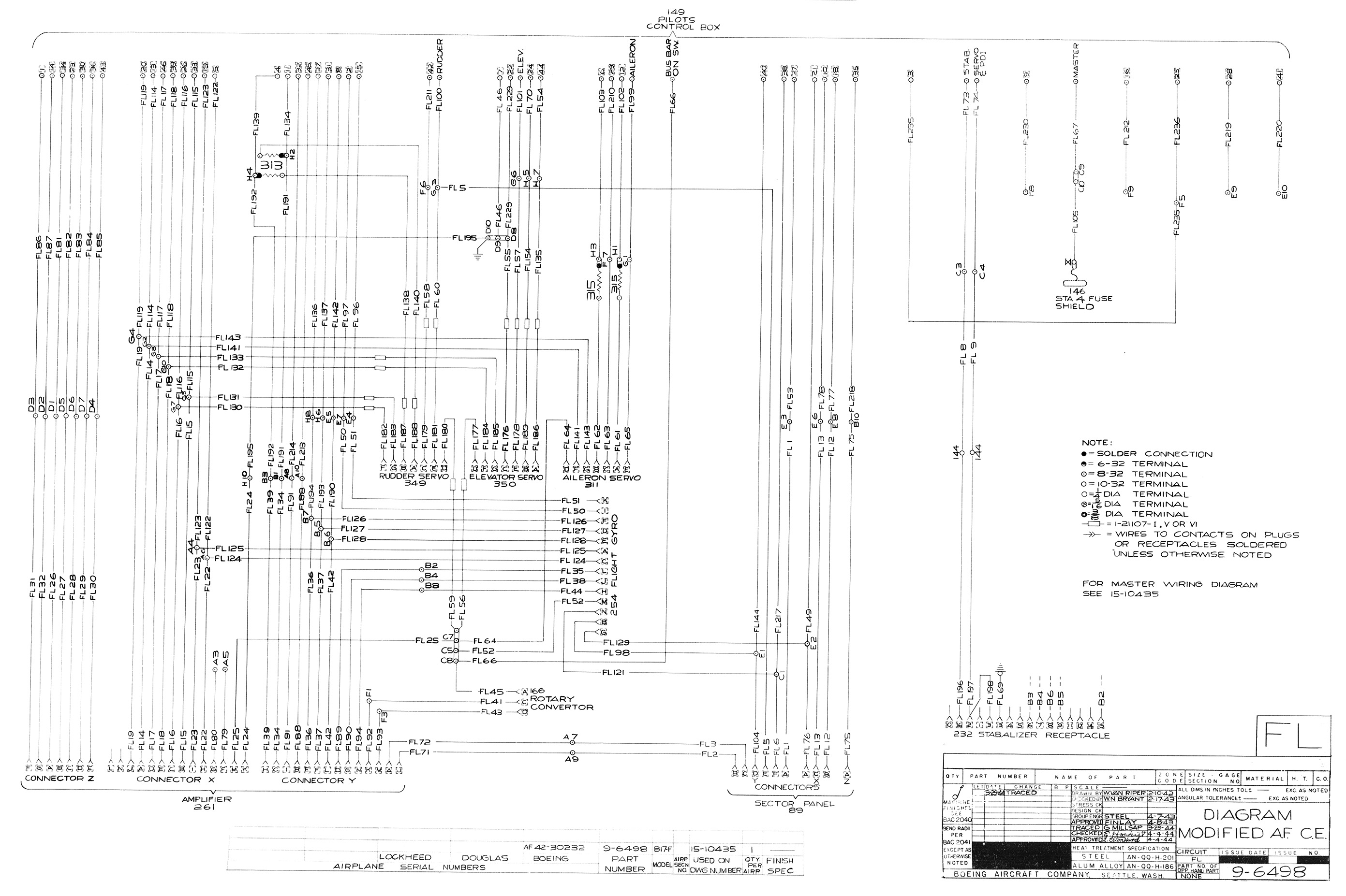
(FL) Autopilot Circuit – Blueprint 9-6498
(I) Ignition Circuit – Blueprint 9-5613
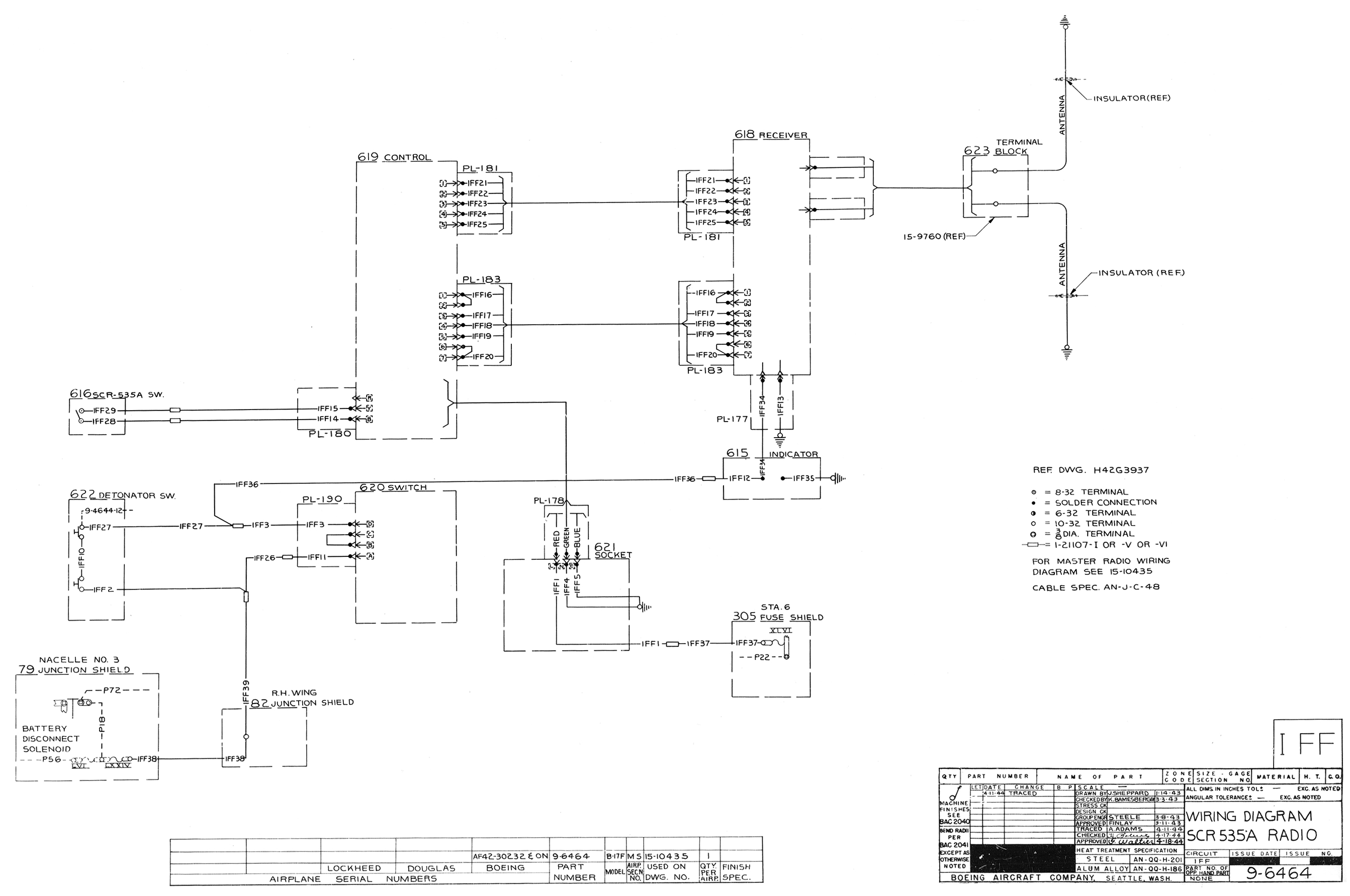
(IFF) Identify Friend & Foe – Blueprint 9-6464
(IN) Intercom Circuit – Blueprint 14-3306
(LR) Liaison Radio Circuit – Blueprint 9-5817
(P) DC Power Circuit – Blueprint 9-5778
(R) Retraction Motor Circuit – Blueprint 9-6463
(RC & MB) Radio Compass and Marker Beacon Circuit – Blueprint 9-5620
(S & PF) Starter & Prop Feather Circuit – Blueprint 9-5770
(W) Warning Signal Circuit – Blueprint 15-10645
It is the goal of Hangar Thirteen to install these circuits as accurately as possible. Period wiring was covered in lacquered fabric, with 3/32 labels (wrapped in Scotch tape) spread at 10 ft intervals to identify each line. Acquiring this much lacquered-fabric wire should prove to be an adventure.
But before then, we must start with the various junction and fuse boxes located throughout the aircraft’s fuselage. This page is intended to serve as a reference for Hangar Thirteen volunteers in that regard.
Blueprint 55-7332: Electrics Installation

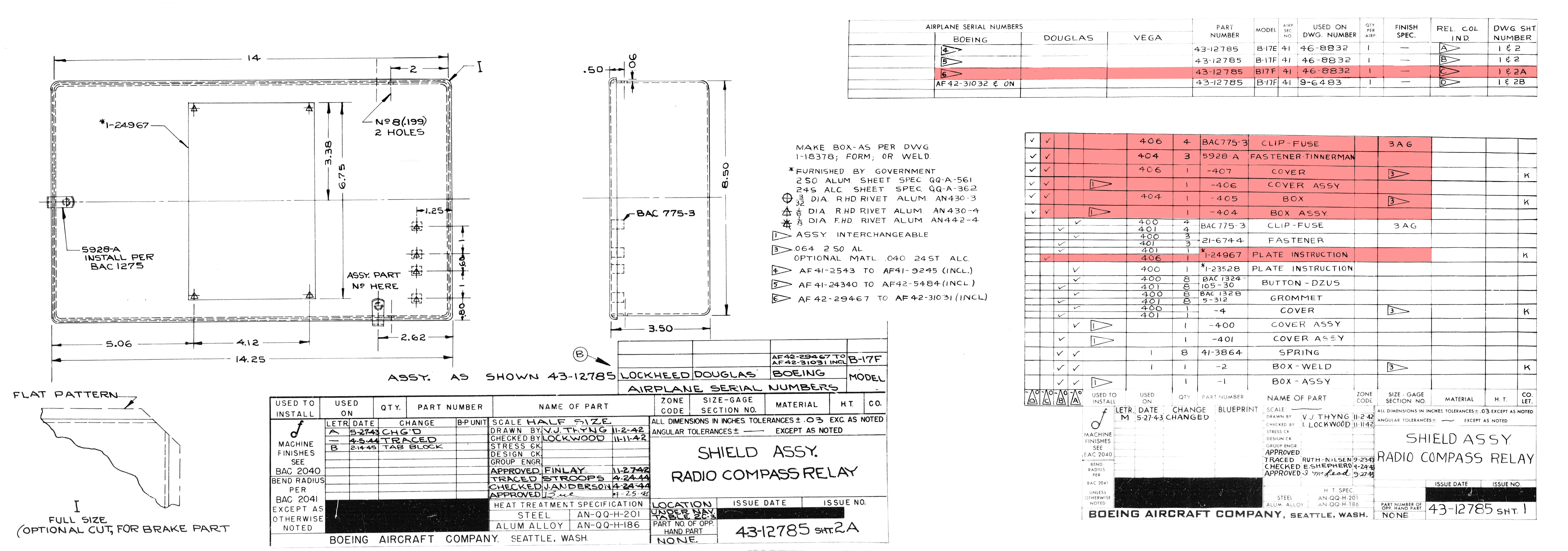
Radio Compass Relay Panel
Radio Compass Relay: 46-8832-B
Components:
BK-22 Relay COMPLETED
2x Fuses – 10 Amp (3AG)
4x Fuse Clips – 3AG
Assemblies:
Fuse Chart (Blueprint 1-27640-2)
Shield Assembly (Blueprint 43-12785-C)
Instruction Plate (Blueprint 1-24967) COMPLETED

Autopilot Junction Box
Autopilot Junction Box: Blueprint 9-6617
Assemblies:
Bus Connector (Blueprint 1-30461), (-1)
Chart (Blueprint 6-15235)
Shield Assembly (Blueprint 9-6612)
Tab Indicator (Blueprint 1-30460-1), (-2), (-3), (-4), (-5), (-6), (-7)
Terminal Block (Blueprint 3-21928)

Voltage Regulator Panel
Voltage Regulator Panel: Blueprint 15-7985-E
Components:
Type B-4 Relay (94-32324)
Assemblies:
Bus Connector (Blueprint 25-862-2)
Cover Assembly (Blueprint 3-14221)
Shield Assembly (Blueprint 14-2870-B)
Channel (Blueprint 9-5040-7), (-8)
Fitting Assembly (Blueprint 9-5040-4)

AC Fuse Panel
AC Fuse Panel: Blueprint 6-10493-C
Components:
2x Fuses – 5 Amp (5AG)
2x Fuses – 10 Amp (5AG)
4x Fuse Clips – 5AG
Assemblies:
Box Assembly (Blueprint 6-10492-B)
Bus Connector (Blueprint 1-26449)
Fuse Chart (Blueprint 1-29928)
Panel Assembly (Blueprint 4-908-5)
Bus Connectors (Blueprint 21-7401-1), (-2)

Cockpit Fuse Panel – Left Side
Cockpit Fuse Panel: Blueprint 55-7538-E
Components:
B-1B (ON/ON) Switch (AN3014/AN3022-3B)
26x Fuses – 5 Amp (5AG)
2x Fuses –10 Amp (5AG)
38x Fuses – 15 Amp (5AG)
8x Fuses – 20 Amp (5AG)
4x Fuses – 30 Amp (5AG)
2x Fuse – 40 Amp (5AG)
6x Fuses – 60 Amp (5AG)
2x Fuses – 30 Amp (1AG)
2x Fuses – 100 Amp (1AG)
172x Fuse Clips – 5AG
24 Volt Relay SC-C-324-D
Assemblies:
Fuse Chart (Blueprint 3-20633) COMPLETED
Fuse Shield (Blueprint 54-2079-C)
Decal (Blueprint 3-16111-9) DRAFTED
Panel Assembly (Blueprint 75-7635-609)
Bus Connector (Blueprint 1-26270)
Bus Connectors (Blueprint 6-10678), (-2), (-3)
43x Bus Connectors (Blueprint 21-7401-1)
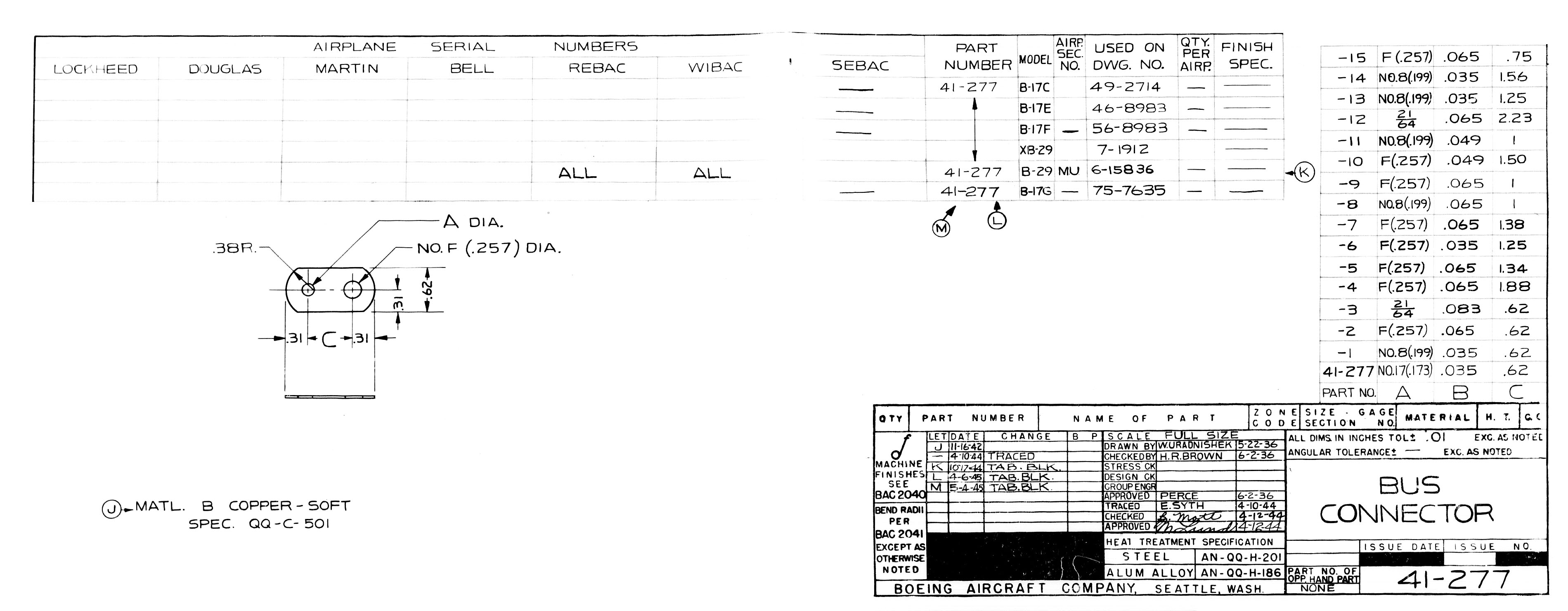
2x Bus Connectors (Blueprint 41-277-11)
Panel Insulator (Blueprint 1-21942)

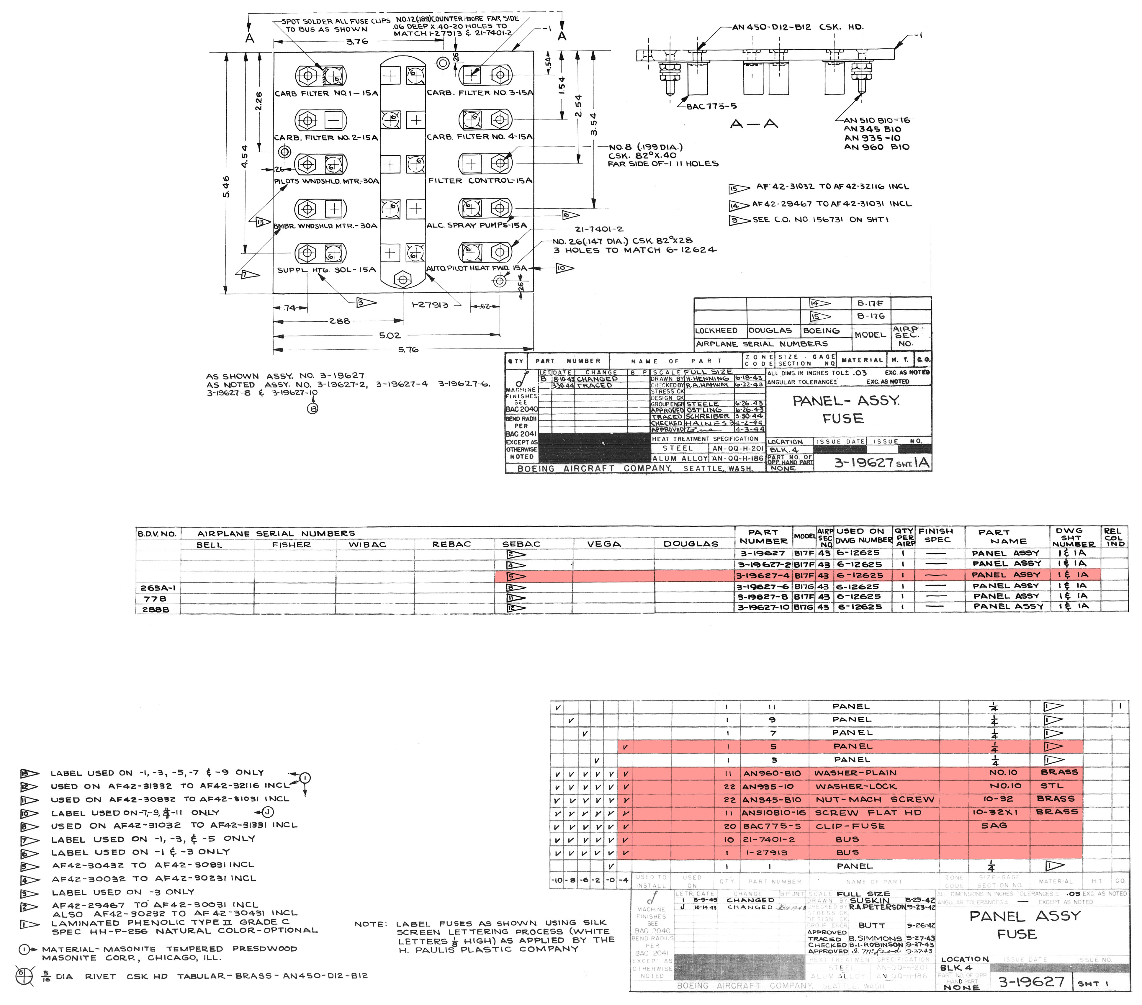
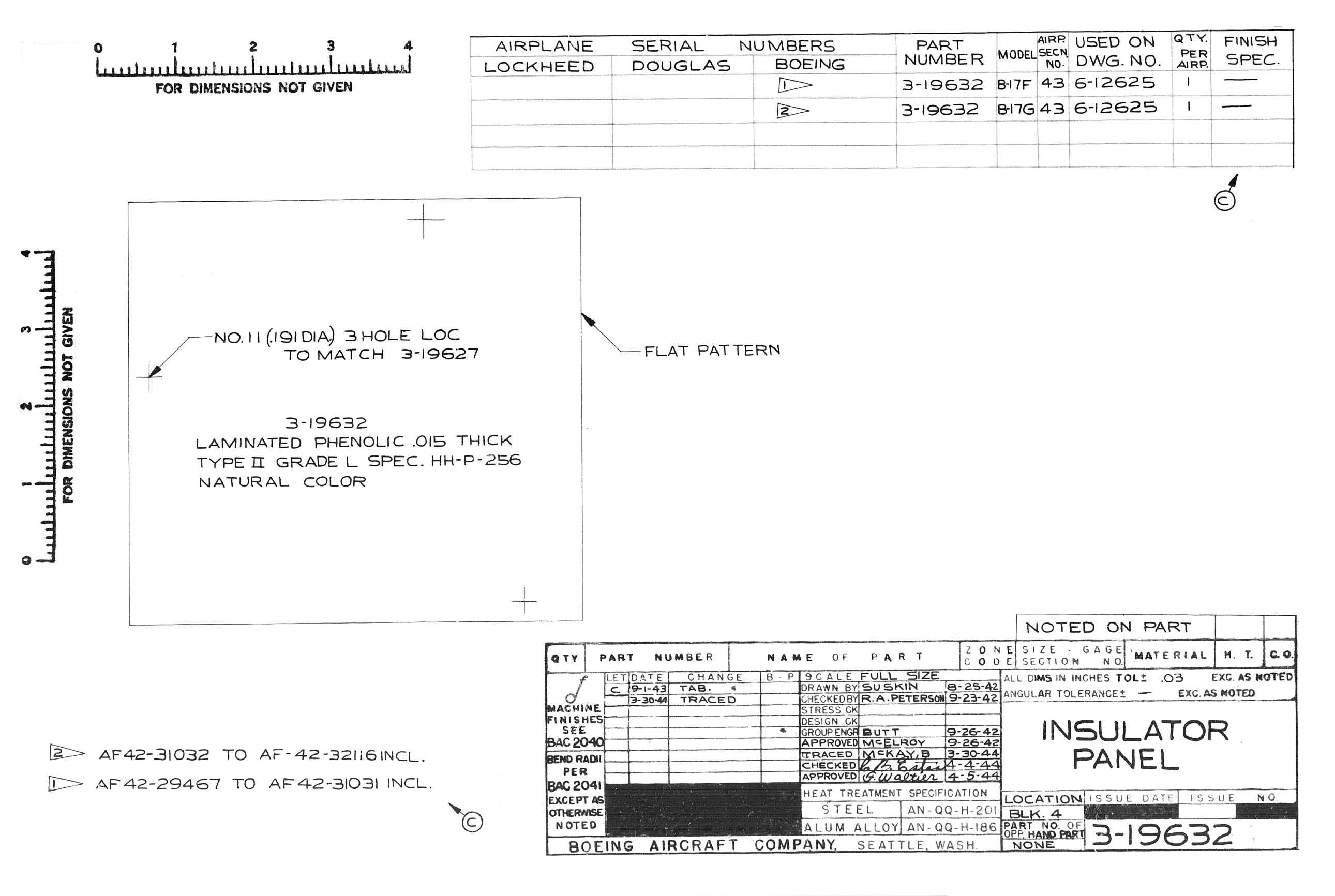
Cockpit Fuse Panel – Right Side
Cockpit Fuse Panel: Blueprint 6-12625-D
Components:
10x Fuses – 15 Amp (5AG)
4x Fuses – 30 Amp (5AG)
20x Fuse Clips – 5AG
Relay – Four Pole, Double Throw 2028 (Leach Relay)
Assemblies:
Fuse Chart (Blueprint 1-29168) DRAFTED
Panel Assembly (Blueprint 3-19627-4)
Bus Connector (Blueprint 1-27913)
10x Bus Connectors (Blueprint 21-7401-2)
Panel Insulator (Blueprint 3-19632)
Relay Assembly (Blueprint 3-16974)

Wing Junction Boxes
Wing Junction Boxes: Blueprint 14-2072-E and -F
Components:
2x CA-275X Capacitors
Assemblies:
Bus Connectors (Blueprint 21-7401-6)
Decals (Blueprint 9-4641-4), (-5)
Insulator (1-25561)
Insulators (Blueprint 3-13696)
Panel Assembly (Blueprint 3-16953)
Bus Connector (Blueprint 1-25543-1)
Panel Assembly (Blueprint 9-3601)
Shield Assembly (Blueprint 6-9325-1), (-4)

Bombbay Junction Boxes – Ignition
Bombbay Junction Boxes – Ignition: Blueprint 6-7889-A-0 and -A-1
Assemblies:
Box Assemblies (Blueprint 21-8364-A)
Decals (Blueprint 9-4641-13), (-14)
Insulators (Blueprint 21-8627)
Connector Assemblies (Blueprint 21-8891)

Bombbay Junction Boxes – Generator
Bombbay Junction Boxes – Generator: Blueprint 6-9509-A-0 and -A-1
Assemblies:
Cover Assemblies (Blueprint 41-9981-2)
Decals (Blueprint 6-10790-2), (-7)

Bomb Rack Junction Box
Bomb Rack Junction Box: Blueprint 15-7967
Assemblies:
Decals (Blueprint 1-24603), (-1)
Decals (Blueprint 9-4641-19), (-36)
Insulators (Blueprint 3-14244)
Panel Assemblies (Blueprint 6-10113)
Shield Assemblies (Blueprint 6-10112), (-1)

Strike Camera Power Receptacle
Camera Power Receptacle: Blueprint 6-12851
Components:
AN3102-16S-6P Socket Receptacle
2x AN3102-16-11S Socket Receptacles
Type B-5A Switch (Single Throw)
BAC768-B6 Connector Assembly
Assemblies:
Plate (Blueprint 6-12649)

Liaison Radio Junction Box
Liaison Radio Junction Box: Blueprint 56-7583-A
Components:
Type C-1B Switch
Assemblies:
Bus Connector (Blueprint 21-7401)
Connector Panel Assembly (Blueprint 21-8891-14)
Decal (Blueprint 6-11943-11)
Insulator (Blueprint 21-8627-14)
Retainer (Blueprint 41-158)
Shield Assembly (Blueprint 6-7625)
Stop (Blueprint 41-159)

Waist Fuse Panel
Waist Fuse Panel: Blueprint 69-3659-D
Components:
2x Fuses – 5 Amp (5AG)
2x Fuses – 10 Amp (5AG)
6x Fuses – 15 Amp (5AG)
6x Fuses – 20 Amp (5AG)
6x Fuses – 60 Amp (5AG)
2x Fuses – 70 Amp (2AG)
22x Fuse Clips – 5AG
2x Fuse Clips – 5AG
P. R. Mallory CA-275X Capacitor (50V)
Assemblies:
Fuse Chart (Blueprint 3-19952-6)
Panel Assembly (Blueprint 7-1646-11)
Bus Connector (Blueprint 1-18567) MISSING BLUEPRINT
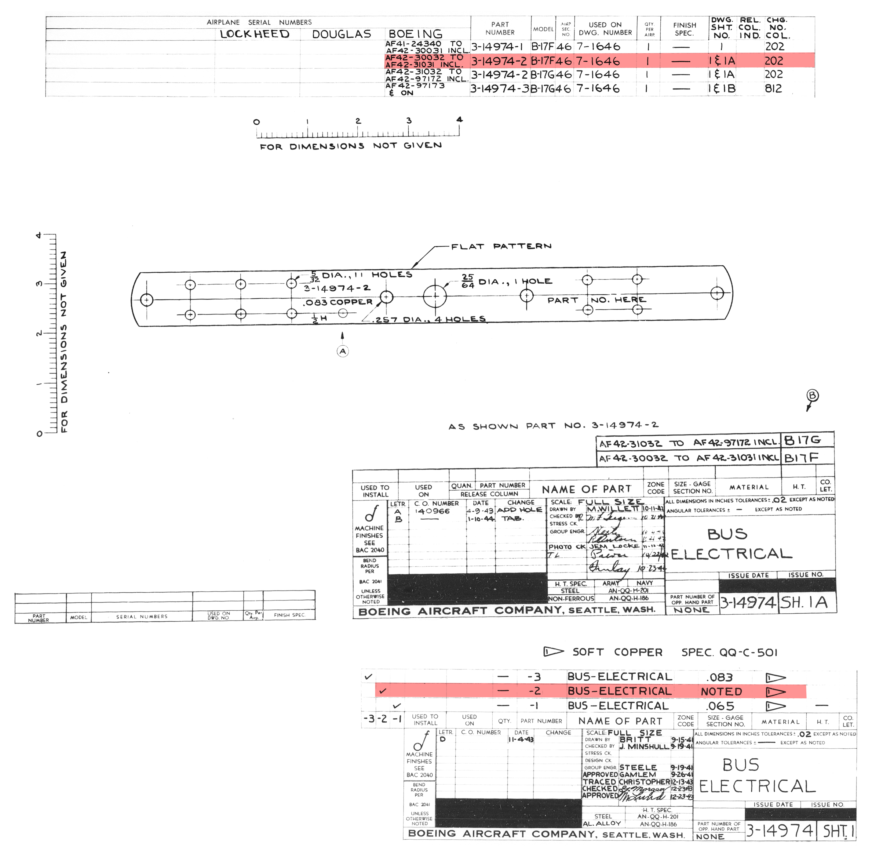
Bus Connector (Blueprint 3-14974-2)
10x Bus Connectors (Blueprint 21-7401-2)
Bus Connector (Blueprint 41-277-8)
2x Washer (Blueprint 41-3996-28-17)
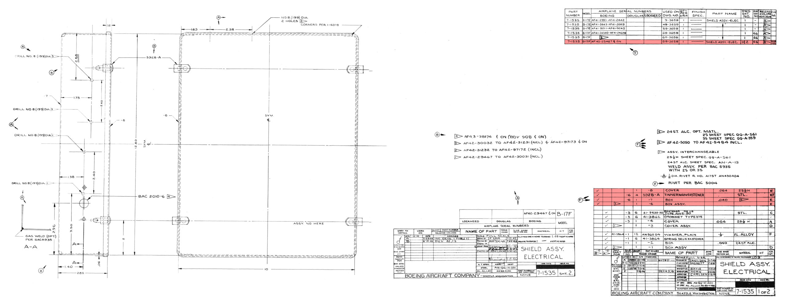
Shield Assembly (Blueprint 7-1535)