
A custom illustration showing an A-1 Upper Turret like the one which was installed aboard Lucky Thirteen.
Lucky Thirteen‘s Needs
When it comes to rebuilding Lucky Thirteen, there are two aspects of the project more difficult than any other: wing spars and turrets. Today we are going to focus on the latter.
For much of the postwar history of Second World War aircraft, powered gun turrets were an afterthought. They were heavy, cumbersome, and took up valuable space – so much so that many warbird owners opted to dispense with their aircrafts’ turrets altogether. This trend was so strong that, when warbird groups began to bring turrets back, resources were scant – both in reference material and actual turret parts. Most of today’s surviving turrets are Frankenstein amalgamations, with many bombers being displayed with turrets completely at odds with what they originally carried.
With our uncompromising dedication to accuracy, it has always been our goal to not only include Lucky Thirteen‘s turrets, but to ensure they are restored to fully operational condition. This will be no easy task. Powered aircraft turrets were as large and complex as small cars. And because of their rarity, turret parts often demand ridiculous sums. We originally estimated needing some 120,000 USD to rebuild the top and ball turrets for Lucky Thirteen, the idea being that each would cost somewhere around 60,000. With the US economy steadily declining, this estimate may have been too conservative. For example, the top turret’s mounting ring (the thin hoop-like piece which connects the turret to the airplane) has been offered to us for 10,000 USD.
Because we are dependent on donations to accomplish this goal, we have not come close to reaching those figures. But we have made progress.
Regarding the top turret body, we have been fortunate in acquiring the platform assembly and dome. As for components, we have acquired the correct gunsight, Edgewater adapters, and hand control assembly, as well as the double power units for both turrets. (Making sure each piece is accurate to our serial makes this process more difficult than one might expect.) Since it seems unlikely that we will ever find an example of the turret’s tub assembly, we managed to contact someone with an A-1 turret who would allow us to 3D scan their example. Once we finish reverse engineering this scan, we can hopefully have the tub assembly cast anew (assuming an original does not find its way here).
The early style interrupter gear, as well as the tub assembly with its various small connecting parts, will prove the most challenging aspect of this already difficult goal. If this technological history write-up is of any interest or use to you, please consider contributing to the rebuilding of Lucky Thirteen‘s powered turrets.
We DO know of one complete Type A-1 Upper Turret that is not installed on an aircraft. The owner has stated that he would be willing to sell if it went to Lucky Thirteen. However, he has not set a concrete price, only acknowledging that it would be expensive. If we were to be able to raise enough to meet his desire, we could purchase the entire turret rather than fundraising bits here and there for a new turret. But we cannot take the offer for a complete turret at face value – if we cannot guarantee its purchase, we must work toward what we know we can accomplish. The route forward is entirely dependent of how much we bring in in financial support.
History
Contrary to popular belief, US Army Air Corps theories about strategic bombing prior to the Second World War were not based on the idea that the bomber could defend itself. Rather, in the absence of radar technology, Air Corps Tactical School instructors postulated that modern bomber aircraft could approach their targets at such altitudes and speeds that they could hit their targets and egress before interception. A minor distinction but an important one. This theory was hotly debated and it certainly did not help that the technologies involved were low priority in US defense spending. As such, while France and Great Britain were experimenting with powered gun turrets as early as 1935, it was not until after the outbreak of war in Europe – and the introduction of early-warning radar – that the United States earnestly began researching powered gun turrets for its bombers.
Observation reports covering the vulnerability of bombers in the Japanese invasion of China and Spanish Civil War seriously troubled the War Department. After all, while the Boeing B-17 was over four years old, it was not ordered into mass production until the 1938 Munich Agreement. The big bomber was expensive and the possibility of it being useless was not easy to stomach. However, reports from Great Britain noted that German fighters eschewed rear attacks against Vickers Wellingtons due to their powered turrets.
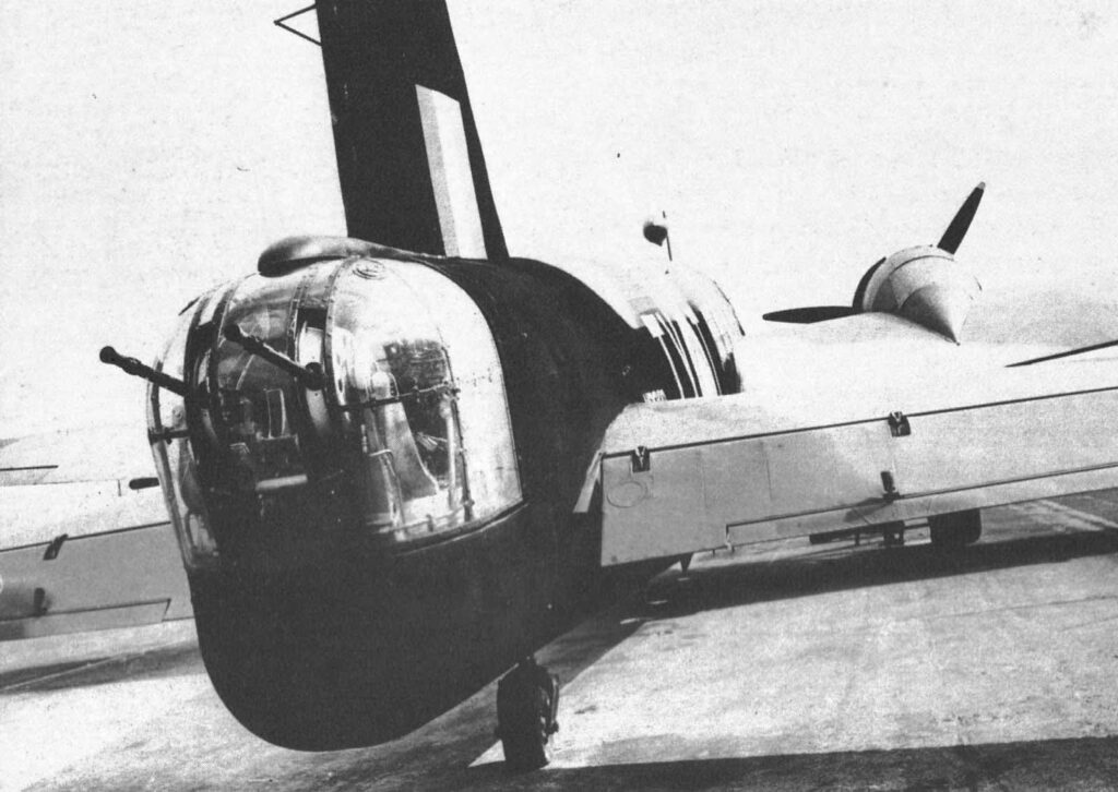
A Vickers Wellington with its Frazer Nash FN-5 tail turret. The first aerial victory using a powered turret occurred on 3 December 1939, when LCpl John J. Copley, tail gunner on “Z for Zebra” (N2879, 38 Squadron), downed a Bf-110C (ZG26) piloted by Lt Günther Specht (who lost an eye).
The world took strong notice of Great Britain’s early successes, with aviation journals particularly lauding where 264 Squadron (a Boulton Paul Defiant unit) claimed 37 aerial victories on 29 May 1940 alone. While these figures were obviously exaggerated, they still contained a kernel of truth: powered-gun turrets worked. A report by LTC Grandison Gardner and MAJ Franklin O. Carroll noted:
The installation of these turrets on some of their bombers had caused such losses to the enemy attacking airplanes that the British now claim that the attacks directly aft have been discontinued on these installations. . . . It is imperative that our heavy and long-range bombers be equipped with at least four turrets. . . The British have shown the way and the method together with the results to be obtained in the installation of machine gun turrets. . . no effort must be spared to apply this type of mechanism to our own advantage.
For their part, the Germans learned to avoid the nose and tail turrets of British bombers by approaching “on the beam” (sideways). This proved frightfully effective as many older aircraft lacked self-sealing fuel tanks, leaving them quite flammable. The solution was obvious: a powered gun turret for all four approaches.
Immediately the USAAC put into place a powered turret program based on the British model, assigning turret manufacturers specific airframes to arm: Sperry for the B-17, Bendix for the North American B-25, etc. Calls were made for sample British turrets and the RAF happily complied, though their request for a sample Norden bombsight in trade was denied (they were property of the Navy not the Army). By the time representatives from Frazer-Nash and Boulton Paul arrived with sample turrets at Wright Field (22 November 1940), several US prototypes were already undergoing testing (such as an electric upper turret by Martin and a hydraulic tail turret by Consolidated).
Sperry Gyroscope, with their history developing bombsights and targeting computers for the US Navy, was a natural choice to design turrets for the B-17. As such, the first two powered aircraft turrets accepted by the US Army were the B-17’s A-1 upper turret and the A-2 ball turret. The latter took some time to develop and the first 112 B-17Es (the first of the turret equipped B-17s) were delivered with a remotely aimed variant of the A-1 as a belly turret. Belly remotes were already falling out of favor due to their disturbing tendency to cause vertigo, with few seeing actual combat use. Sperry formally applied for patents on the A-1 and A-2 on 24 October 1941.
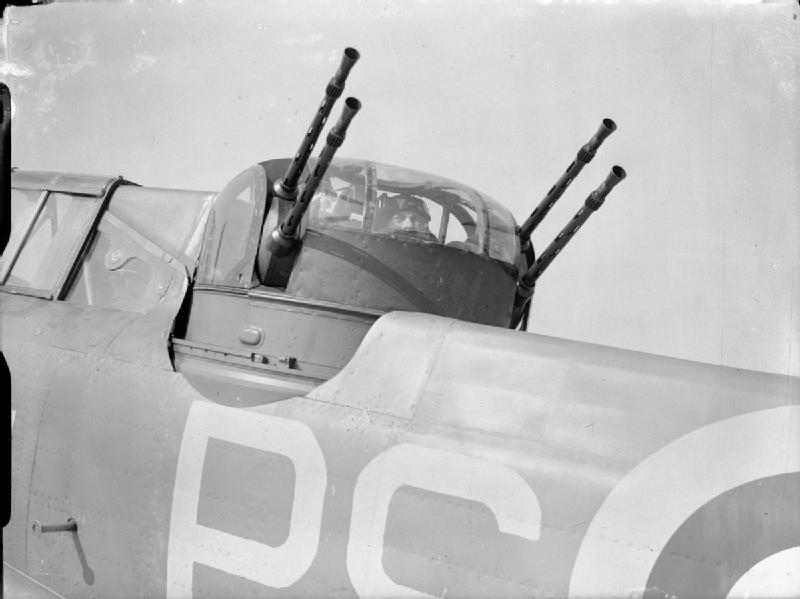
A Boulton Paul Type A turret installed on a Boulton Paul Defiant. Note the resemblance between it and the Sperry A-1.
Sperry’s designs were heavily influenced by Boulton Paul of Wolverhampton, England. Unlike competitor Frazer-Nash, whose hydraulic turrets were directly connected to the aircraft, Boulton Paul’s system was self-contained, allowing turrets to be swapped out for maintenance and repair. This system was first developed by J. B. Antoine de Boysson of France, who licensed his turret to Boulton Paul in 1935 after being expected to bribe his way into a French contract. As such, the turrets were powered by an electric motor sandwiched between a pair of hydraulic transmissions. This “double power unit” was identical for both the A-1 and A-2. Since Sperry was incapable of manufacturing the turrets in-house, the turrets were license built. The upper turrets were built by Steel Products & Engineering (SPECO) of Springfield, Ohio and the ball turrets by Briggs Manufacturing of Detroit, Michigan. Rather appropriately, considering Briggs’s history as an autobody producer, the double power units were produced by nearby Vickers Hydraulics (no relation to the British firm).
It is worth noting that the Vickers plant was identified after the war as being one of the few strategic bottlenecks in the US war economy, as no other plant produced double power units for Sperry turrets. This was not by choice. Vickers reacted violently to an attempt by Emerson Electric to supplement power unit production, in the process revealing that their production shortages were, in reality, a ruse to coerce a larger defense contract.
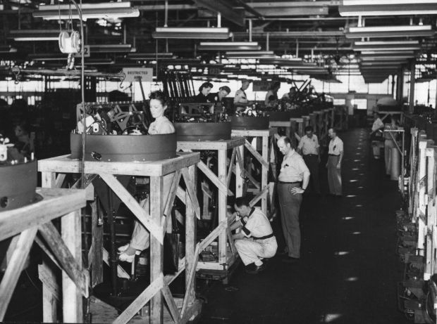
The A-1 Turret production line at Emerson Electric.
W. Stuart Symington III, upstart president of Emerson Electric of St. Louis, Missouri, oversaw a massive expansion which saw a new turret-producing wing, openly catering to supplement turret production on aircraft beyond those assigned to his company (the Consolidated B-24). While this was bitterly resisted by Briggs, SPECO welcomed the assistance, and Emerson manufactured large numbers of both A-1 and A-2 turrets. (The ball turret used on the B-24 was designated the A-13, being differentiated by its hydraulic retraction system necessitated by the B-24’s low ground clearance.)
The Sperry A-1 Upper Turret
The Sperry A-1 top turret was produced in three variants: the A-1, the A-1A, and the A-1B. A fourth variant, the A-1C, was designed but, according to the Boeing installation blueprint, never actually put into service. This is further supported by the A-1C’s manual, which was not published until after the war on 25 October 1945. In general, turret variants were installed thusly:
Type A-1 Upper Turret
B-17E through B-17F-80-BO
SP-1 – SP-1640
E-1 – E-2700
Type A-1A Upper Turret
B-17F-80-BO through B-17G-90-BO
SP-1641 – SP-6550
E-2700 – unk.
Type A-1B Upper Turret
B-17G-90-BO through B-17G-110-BO
SP-6551 – unk.
It should be noted that Boeing prints do not specify changes in aircraft license-built by Douglas and Lockheed-Vega. Likewise, there was also a large discrepancy between SPECO and Emerson regarding construction of turrets. While SPECO was a specialty producer, Emerson turrets were built on an assembly line. This is why, for example, SPECO went through five dome variations while Emerson only changed domes once.
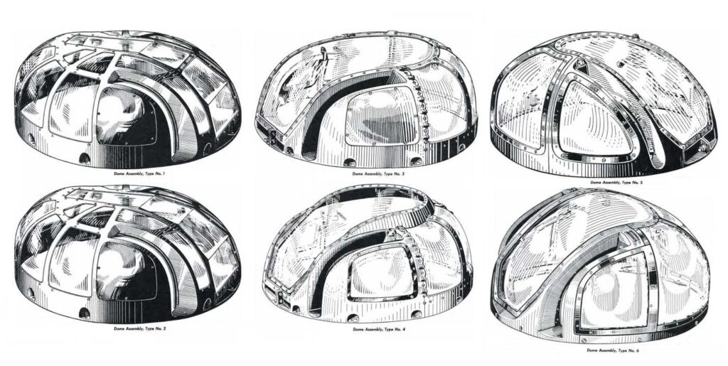
Dome types are listed vertically, with odd numbers being the upper row and even numbers the bottom row.
For example, SPECO produced some 1,640 A-1 turrets while Emerson produced 2,700; while the former used Type 1 and Type 3 domes, changing at SP-723, all 2,700 Emerson A-1s used the same dome, the Type 2. While it is tempting to differentiate the Type 1 and Type 2 dome by the removed center window frame on the Type 2, in reality, these domes were identical, with the removal of the center window frame being a later concession to the obsolescence of the design.
This is how, when viewing pictures of B-17Fs and early B-17Gs, one can distinguish whether the aircraft had an Emerson or a SPECO A-1 installed (assuming the domes had not been switched).
To continue this example, let us compare King Bee (42-3474, 100BG) and Lucky Lady II (42-30290, 96BG).
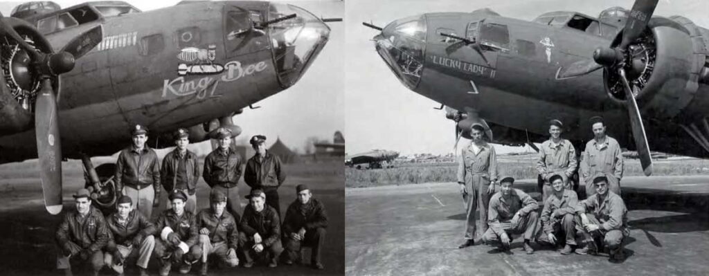
Both of these aircraft were of similar age, being late-Fs which entered service in 1943. While Lucky Lady II was a Boeing-built F-model, King Bee was a Douglas-built F-model. Looking at the photos, we can tell that Lucky Lady II had a SPECO installed because of her Type 3 dome, and King Bee had an Emerson installed because of her Type 2 dome. Admittedly, it is possible that the domes on these turrets were swapped out, but photos of other aircraft suggest that Emersons were more prevalent on license-built B-17s than SPECOs.
This should come as no surprise. Since Emerson built on a production line, it was more difficult for them to implement changes in design. As such, Emerson built turrets evolved far slower than those built by SPECO. In fact, Emerson only produced A-1s and A-1As, as the A-1Bs were entirely built by SPECO. Emerson-built A-1s had Type 2 domes while Emerson-built A-1As had Type 6 domes. All other dome types were used by SPECO. The Type 6 dome (known as the “Ainsworth Dome”) was the only dome used by both Emerson and SPECO.
The A-1 and A-1A turrets were very much alike, with the shift from one model to the other being almost fluid in its evolution. If we focus strictly on SPECO turrets however, this task becomes easier. Partway through the A-1A series, the platform assembly was redesigned to lessen the turret’s weight. This feature was expanded on the A-1B to include a redesigned tub assembly, seat strap, and foot stirrups, while increasing the ammunition complement from 800 to 1,400 rounds.
To roughly describe the turret’s design, the electric motor provided power, which was amplified using the hydraulic transmissions on either side: one for azimuth and one for elevation, each connecting to a gear assembly. The elevation gear assembly was more complex than the azimuth as, rather than a single unit, it was two gears on opposite sides, joined by center linkage. The gunner stood on height adjustable stirrups, his bottom resting on a sling and his shoulders in the opening of large V-shaped rails. These rails held the turret’s ammunition in stainless steel cans. As the war progressed, SPECO implemented several weight-saving measures into their turrets, adding lightening holes to the tub, downsizing the base assembly, and replacing the stainless steel ammo cans with galvanized aluminum ones. Emerson was slower to adopt such alterations.
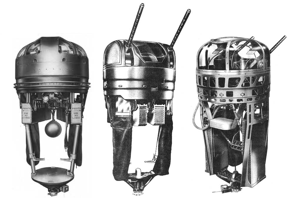
From left to right: an early A-1, a late A-1A, and an A-1B.
Some of the major design changes in the A-1 series:
SP-1 – SP-1202
E-1 – E-1049
The charging bracket was redesigned after these turrets as the side mounted G-4A solenoid was replaced by the G-11, which fitted on the M2 .50 caliber MG’s buffer tube.
SP-1 – SP-1640
E-1 – E-2700
The shutter assemblies for the guns were redesigned after these turrets from a two-part watchchain-like shutter under the guns with a plexiglass shutter above, to an all-metal shutter.
SP-1 – SP-1202
E-1 – E-1851
The hand controls were redesigned after these turrets. The range reticule for the gunsight was controlled by a thumb wheel on the first design and by a motorcycle grip on the second. The push-to-talk switch was also changed, from a footswitch to a thumb switch located on the hand control.
SP-1 – SP-2548
E-1 – E-3060
The Sperry designed interrupter gear assembly was replaced following these turrets with a SPECO designed one that allowed the guns to depress 5 degrees below horizon level. This necessarily saw a slight alteration to the hand control assembly (which interlocked with the interrupter).
SP-1 – SP-599
E-1 – E-350
The interrupter gear was slightly altered after these turrets from being purely mechanical to using electric relays.
SP-1 – SP-1275
E-1 – E-1076
Manual hand cranks for azimuth and elevation were removed after these turrets. The attachment point for the hand drive on the azimuth gearing was covered by a plate until turrets SP-1652 and E-1177, after which the attachment point was removed entirely.
E-1 – E-1851
The Type B-7 trouble light was moved from the center rail to the hull of the turret’s tub assembly following these turrets. This brought Emerson turrets in line with what was standard practice for SPECO, who first introduced the trouble light on turret SP-601.
SP-1 – SP-1201
E-1 – E-816
The constant flow oxygen system, using the Type A-9 regulator, was replaced by the demand flow oxygen system following these turrets, using the Type A-12 regulator.
SP-1 – SP-1652
E-1 – E-1851
The Type F-1 Oxygen Tank, located between the gunner’s legs on a swivel, was removed following these turrets, the platform being replaced by one with an oxygen swivel connecting the turret to the B-17’s oxygen supply.
SP-1 – SP-1717
E-1 – E-1943
The cast rails were replaced with a simpler steel rail design following these turrets.
SP-1 – SP-2260
E-1 – E-999
The sling type seat was supplemented with a padded seat cushion following these turrets.
SP-1653 – SP-4754
The platform assembly was redesigned after these turrets to reduce weight. The resultant design changed the platform from a circle to an hourglass shape. Emerson turrets did not make this change.
SP-1 – SP-3205
E-1 – E-3179
Electric ammunition boosters were added following these turrets.
SP-1202 – SP-2611
E-817 – E-2700
The Type A-1 Oxygen Flow Indicator was replaced with the Type A-3 Oxygen Blinker following these turrets. Similarly, the oxygen panel was shifted from a vertical to a horizontal design.
SP-1 – SP-2611
E-1 – E-3060
Turrets following these serial numbers were equipped with a rheostat-type electrical flight suit heater.
SP-1 – SP-600
E-1 – E-1300
Turrets following these serial numbers had a NF2-1 Filter (100 Amp) installed at the base for intercom noise.
Stay tuned for Part 2, where I will cover the ball turret in detail…