
We have a lot of big news coming up in the next couple months that I think everyone is going to love. I know many of you are eager to see what kind of top turret components we are getting as a result of the April fundraiser. Fred is gathering up turret components now – when he’s ready, we will come down and pick up everything we can afford.
For now I just wanted to share some awesome donations that have come our way.
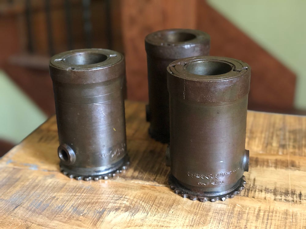
First up is a full set of starters for the B-17F’s Wright R-1820 Cyclone Engines. These were donated by Troy Westrum of Norwalk, Iowa and delivered to us via Eric B Miller of Project Warbird. Eric was up gathering parts for various projects, including his newly-started Vultee BT-13 Valiant. These starters are Eclipse Type F-2s, one of two types used by the B-17 (the other being the G-6). From what I can find, the big difference is that the F-2s could be started using a manual crank, if necessary. Thanks to Troy for this incredible donation!
Next are a series of items contributed Steve Hester of Falls City, Texas. Steve has sent us some amazing pieces lately, and I thought I might share some such as this Type A-3 Gunner’s Safety Belt. A rarely seen piece, this item was design to anchor the waist gunners to the airplane, as this position often operated in open windows. Wrapping through the gunner’s parachute harness, this belt not only kept the airman from being tossed around (or even out) but could also be used to keep his parachute pack nearby. Not counting the seatbelts used by the six seated positions, this means that Lucky Thirteen just needs two A-4 Gunner’s Belts (for the turrets) and one more A-3.
Another recent arrival from Steve was a set of AN5795-6 Dual Temperature Gauges. The B-17F carried four of these gauges, and while we had a full set, two had defects. The gauges that Steve located were in various conditions, but between them and the aforementioned two, I was able to swap and clean various parts to ultimately get a fully restored set. Thanks to Steve’s help and some recent acquisitions, we are now only three gauges away from a full set of wartime gauges for the cockpit instrument panel – all with the correct green UV glow
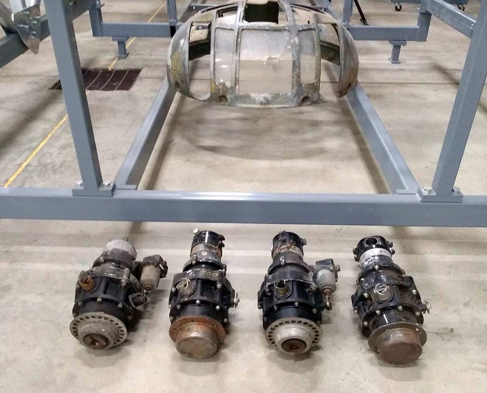
Troy’s newly donated Type F-2 starters lined up in front of the Type A-1 Upper Turret dome.
A major project will soon be underway to repair the damaged area under the left gun port of the dome.
Photo taken 17 May 2022.
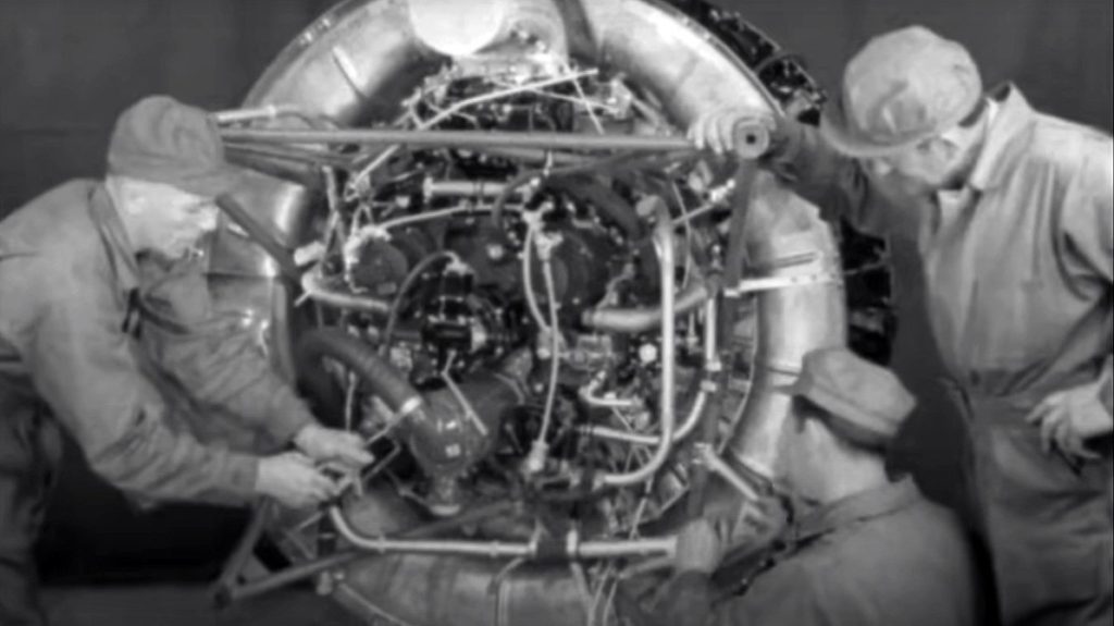
A screencap taken from the The B-17F Engine Installation Series: Engine Build-Up training film. The starter – which in this film is a G-6 – is hard to see because of the poor resolution, but is located nearly dead center on the back of the engine.
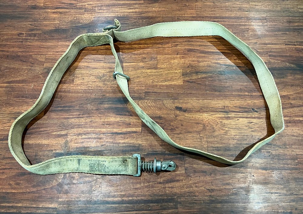
Steve’s newly donated Type A-3 Gunner’s Safety Belt.
Photo taken 17 May 2022.
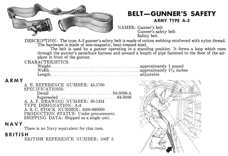
The entry from the Army Index on the A-3 Safety Belt and its usage.

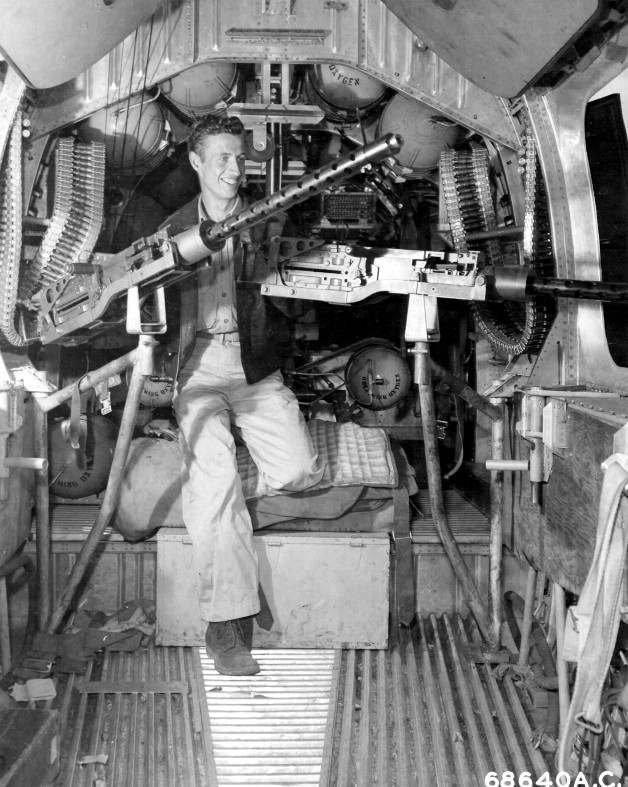
A waist gunner on a late-G model B-17 with his Type A-3 Safety Belt attached. Toward the end of the war, as the Luftwaffe became less of a threat, it was not uncommon for US bombers to have both waist positions manned by a single gunner.
Judging by various clues in the photo, this is most likely a Douglas-built B-17G.
The waist position aboard a Consolidated B-24. Note the A-3 Safety Belts left on the floor.
Behind the airman are the gunners’ flak jackets, casually left on top of the bomber’s Type A-13 Ball Turret. The Type A-13 differed from the B-17’s Type A-2 series in that it could be retracted into the airplane to reduce drag.
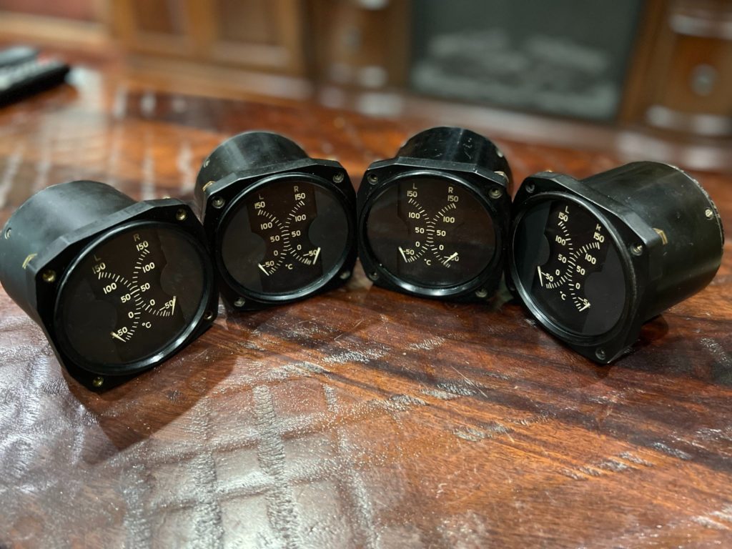
The newly cleaned and restored AN5795-6 Dual Temp. Gauges. Three were made by Electric Auto-Lite of La Crosse, Wisconsin and one by Thomas Edison of West Orange, New Jersey.
It’s a thrill to finally have a set that fully match!
Photo taken 16 May 2022.
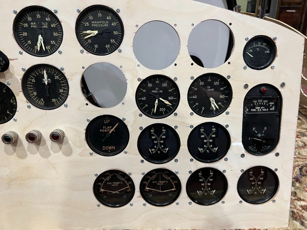
The AN5795-6 Dual Temp Gauges installed in the wooden panel mockup. The holes above are for the needed Fuel Pressure Gauges (x2) and Tachometer (x1).
One aspect of the B-17’s panel that often surprises is that the needles were not numbered to coincide with the engines. Rather, the labels underneath each gauge noted “L for 1,” “R for 2,” etc.
Photo taken 16 May 2022.
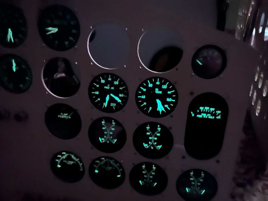
While this photo is rather blurry, you can still see the effect UV/fluorescent light has on the gauges.
The light used for this photo was little more than a handheld cat toy.
Photo taken 16 May 2022.
My apologies for being tardy in our updates. We have all been busy lately!
Just in case you are curious, here are some pics of one of my current projects: the reel antenna.
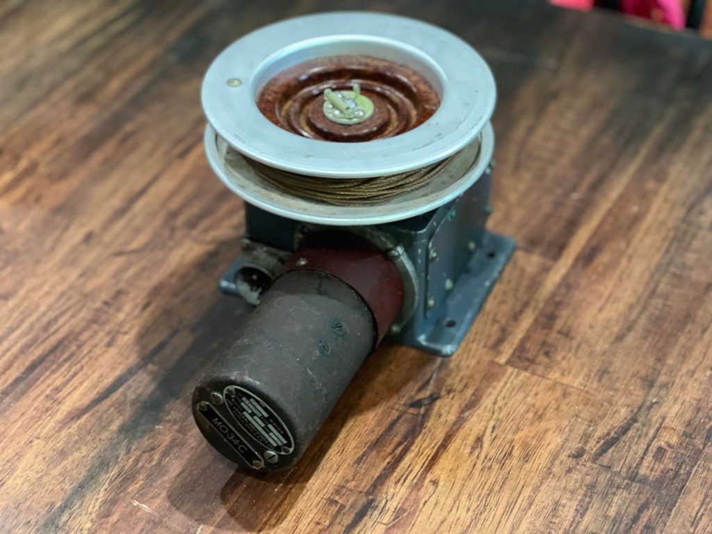
The RL-42 Reel Antenna was a part of the SCR-287 Liaison Radio – the largest of the Boeing B-17’s radio systems. Located near the ball turret, the RL-42 served as a backup to the main antenna, which ran a long wire from the radio compartment to the aircraft’s vertical stabilizer. Should the radio operator need a stronger signal, he could switch between antennas using a SW-224 Knife Switch and spool out the RL-42.
The copper wire could spool some 90 ft, using a 5 lb lead weight (a WT-7) to pull it taught. Power was provided by an electrical junction box, also located by the ball turret, providing current to the spool motor and its control switch, located in the radio operator’s compartment. Talking with 384BG radio operator Don E. Hilliard, Don told me that while he had to qualify using the RL-42, he did not recall any situation that required its use overseas.
We have been rather fortunate with this system. Our F-10 Phenolic Tube was donated by David Green of Ventura, California in 2019, who acquired it from a man who planned on using it (and others) to build a fence! The RL-42 Motor was donated by John B. Wilson of Sapulpa, Oklahoma and the rare early-style BC-461 Control Box by Jack Antonio of Warner-Robins, Georgia (who also provided the appropriate tuning cable). The ‘unobtanium’ MC-163 Fairlead was donated by Joe McKowen of Gaffney, South Carolina.
Older B-17s like Es and Fs used a different clamp system for the reel antenna than most aircraft, and we replicated this mount back in 2020. Having located the MC-163, we are now ready to build a display for this unit – which will be mounted upstairs along with the other radios, once said wall is finished. I recently finished cleaning the RL-42 motor, swapping out some parts with other examples, and installing a NOS wire bobbin, reeling all 90 feet by hand (Toonces the Cat loved that).
Charlie is currently working to restore the Amplifier for the Fluxgate Compass System, though he offered to put together a makeshift junction box to power the RL-42 display. Since Bob Hachmann was already working to model the autopilot junction box and Station 4 fuse panels, Bob suggested we make an inventory of every fuse and junction box in the fuselage. So we did. If any of you would like to volunteer and are experienced with metal fabrication, that would be an excellent way to get started – after all, the B-17 had a lot of electrics…
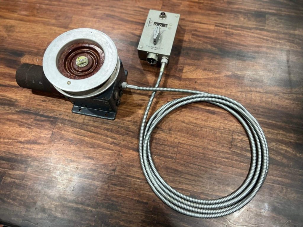
The RL-42 Reel Antenna motor and control box for Lucky Thirteen, all cleaned and ready for display.
Now to build the display for them…
Photo taken 3 May 2022.
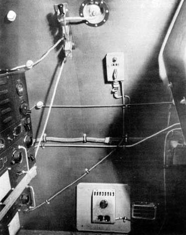
A manual illustration of the radio operator’s left wall. The SW-224 is at the top. Its upper position connecting the fuselage antenna and the lower the reel antenna. Ceramic beads cover the wires which connect to it. Nearby is the BC-461 control box.
Other items of note in the photo are the radio operator’s Q-1B Rheostat (complete with asbestos lined backplate) for flightsuit heat and a nearby vent intended to blow hot air from the wings.
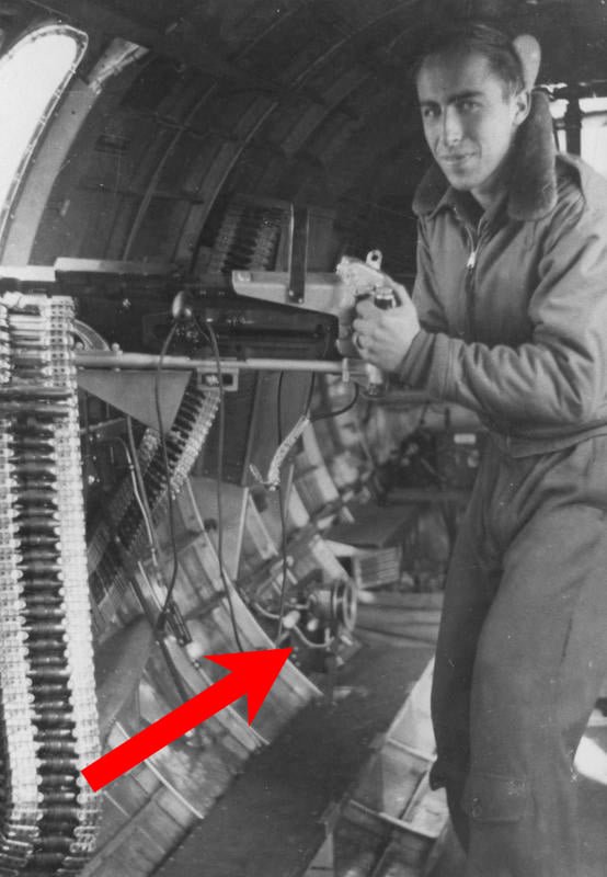
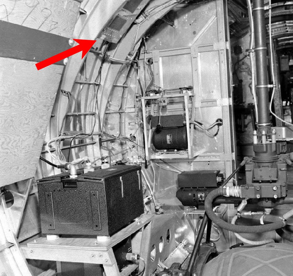
SSGT Ralph E. Azevedo poses in his position as Left Waist Gunner aboard Qualified Quail (42-97851, 91BG). The RL-42 Reel Antenna Motor and Spool is highlighted here.
Damaged over Cologne, Qualified Quail crashlanded in Allied-occupied France on 14 January 1945 and was salvaged. Azevedo was not with them, having been previously wounded and, upon recovery, transferred to another crew.
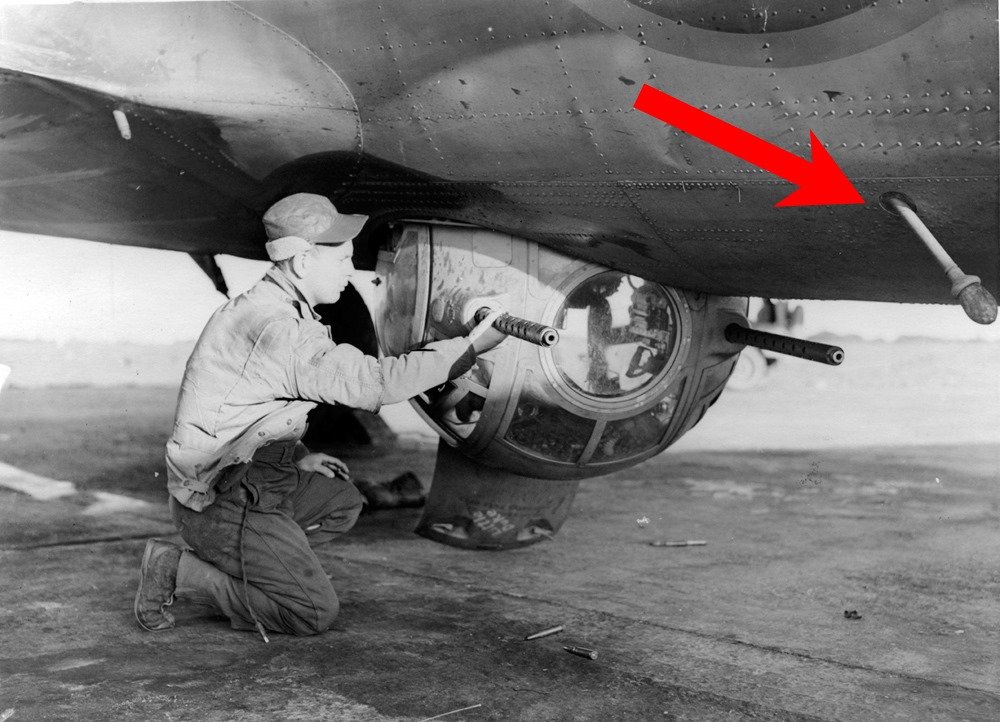
The F-10 phenolic tube for the reel antenna is highlighted on Cabin In The Sky (42-30338, 390BG).
A late-F almost identical to Lucky Thirteen, Cabin In The Sky survived the war and was ultimately sold for scrap.

The RL-42 Motor is cleaned and the newly-threaded bobbin installed.
Photo taken 28 April 2022.
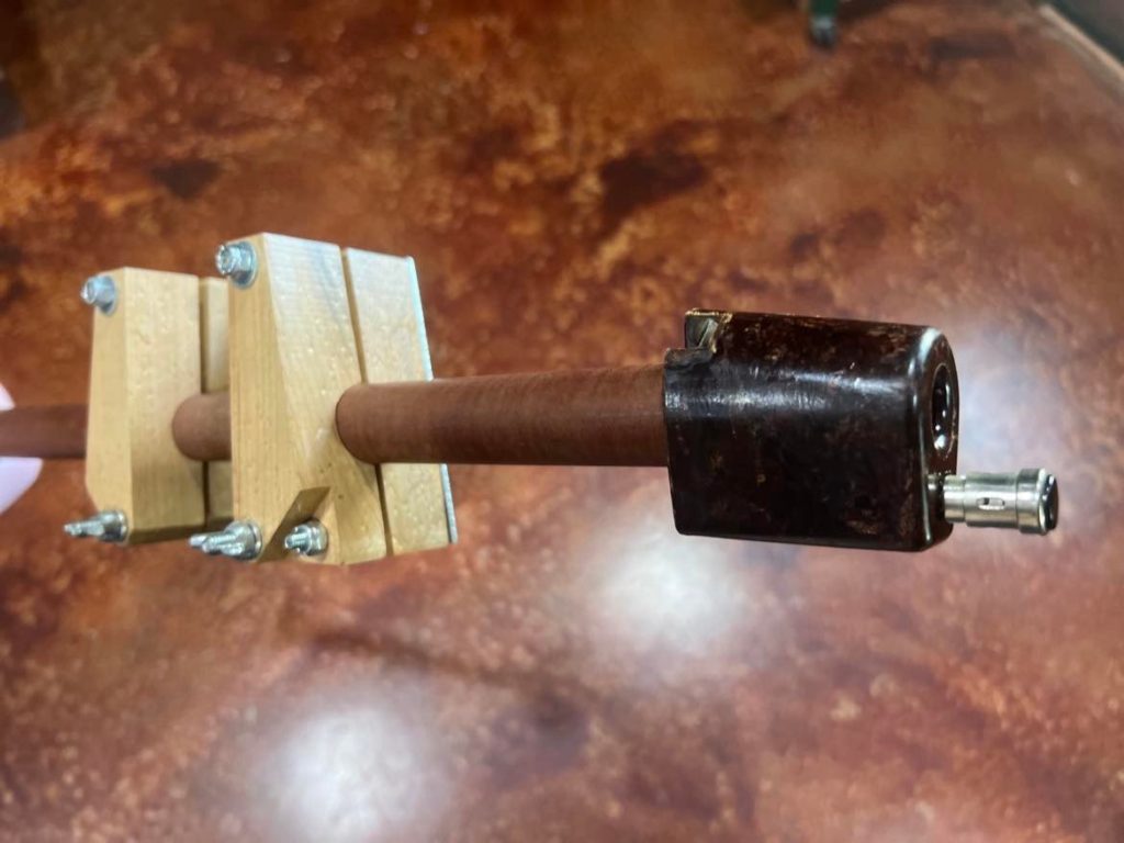
The MC-163 Clamp is installed onto the F-10 Tube.
Photo taken 20 April 2022.
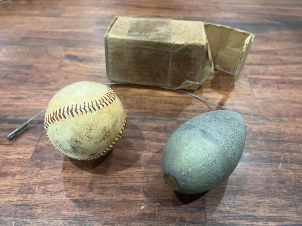
The NOS WT-7 Trailing Antenna Weight with a baseball for size comparison.
Photo taken 20 April 2022.
The Junction Box which provides power to the RL-42 Reel Antenna. Note the wooden shelf below, which holds the bomber’s SCR-522 VHF Antenna.
The shelf on the wall behind holds the dynamotor powering the SCR-287’s transmitter on the other side. The IFF Transponder, normally mounted above, has been removed for this photo.
We were visited by Jim Zazas yesterday, a USAF veteran and vintage aircraft pilot. Like Shawn Knickerbocker, who visited last August, Jim has stick time touring Boeing B-17s and Consolidated B-24s. We had a great time hanging out and chatting, and we look forward to seeing him again in the future!

The newly-arrived mag switch linkage.
Volunteer Bob Hachmann CAD modelled this assembly, and his model was used to 3D print it in aluminum.
Photo taken 18 April 2022.
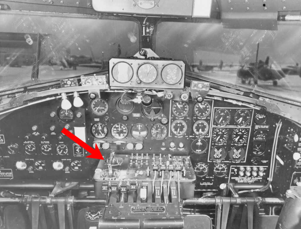
The linkage over the dual mag switches are highlighted in this F-model B-17 cockpit.
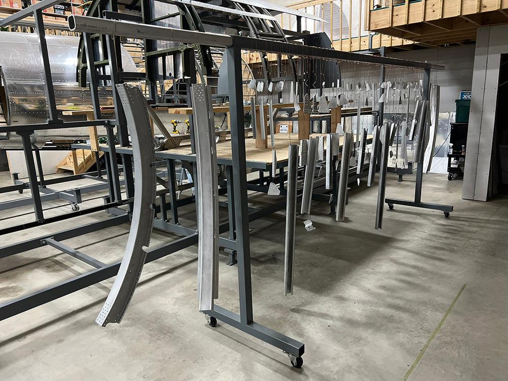
The various ribs and braces for Station 5 (the front wall of the radio compartment) are prepared for finishing.
Different companies had different practices to counter corrosion caused by dissimilar metals. Douglas-built B-17s regularly dipped pieces in zinc chromate, leaving the aluminum skin bare.
We mimic this practice. The pieces you see here will be dipped in zinc chromate, mixed with black pigment (as per wartime practice), which will give them a green color.
The bare aluminum skins that will go over these pieces have already had period-correct ALCLAD markings applied applied to them.
Photo taken 19 April 2022.
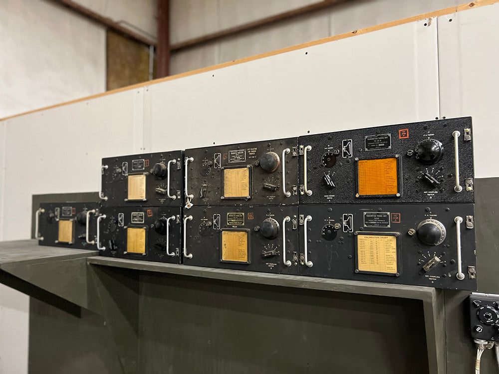
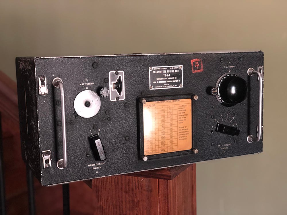
The newly-arrived TU-6 Tuning Unit is placed alongside its comrades for the SCR-287 Liaison Radio System.
These units were stacked against the back wall of the radio compartment, each covering a different frequency range for the giant BC-375 Transmitter.
We are fortunate to have locate pristine examples of all seven units designated for the B-17.
Photo taken 19 April 2022.
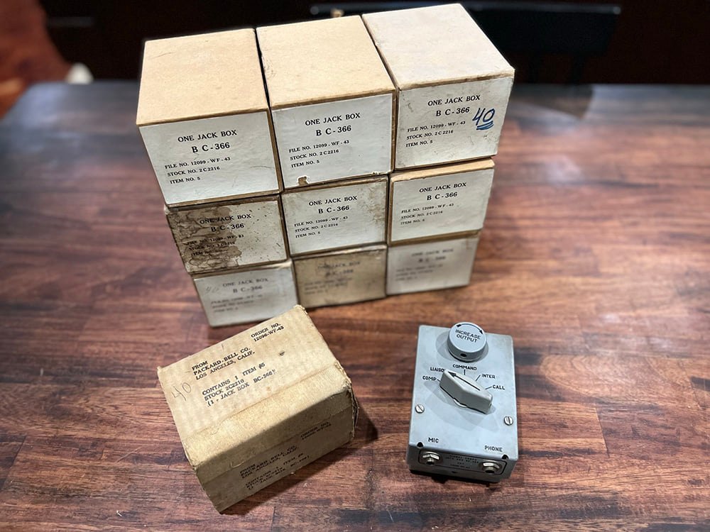
One of the pieces dropped off at the hangar yesterday – a giant collection of BC-366 Intercom Jack Boxes, donated by Joe McKowen of Gaffney, South Carolina.
We now have a fully complement of intercom jack boxes, all of which match – a great thing for obsessive guys like us! Ha!
Photo taken 18 April 2022.
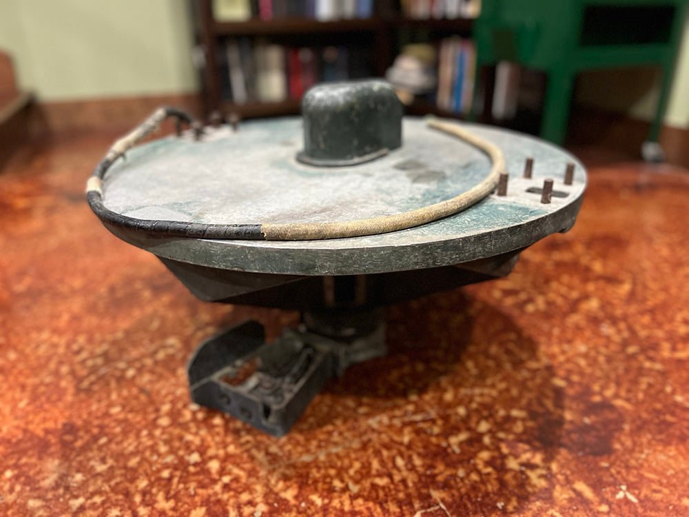
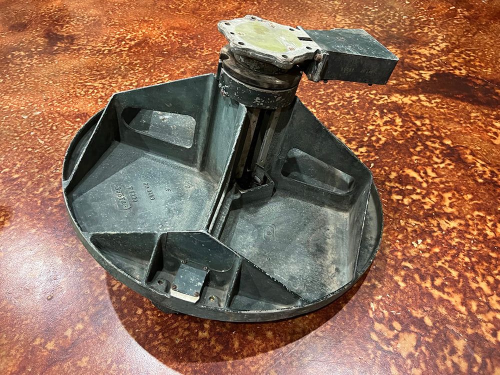
It occurred to me recently that we never took any beauty shots of the top turret base we got from Belgium.
This turret base was removed from “K-King” (44-6139, 351BG), a B-17G which crash-landed near Villers-lez-Heest on 12 September 1944. A combat veteran, it will be restored to working condition as part of the top turret for Lucky Thirteen.
Photo taken 18 April 2022.

Jay Elko’s newly donated NOS Type C-12 Altimeters.
Photo taken 9 April 2022.
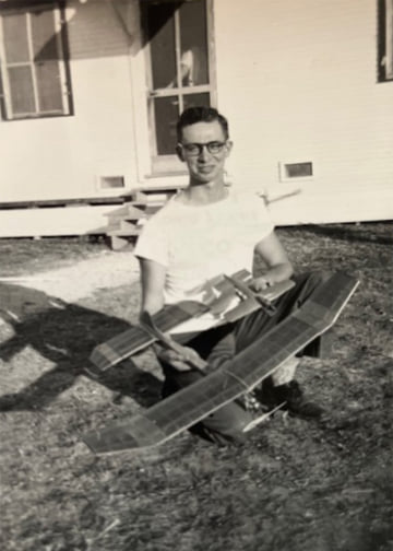
John M. Elko, Jr. posing with a pair of his RC aircraft.
John’s preference was for free flight and controlled line types, and Jay still has some of John’s old models.
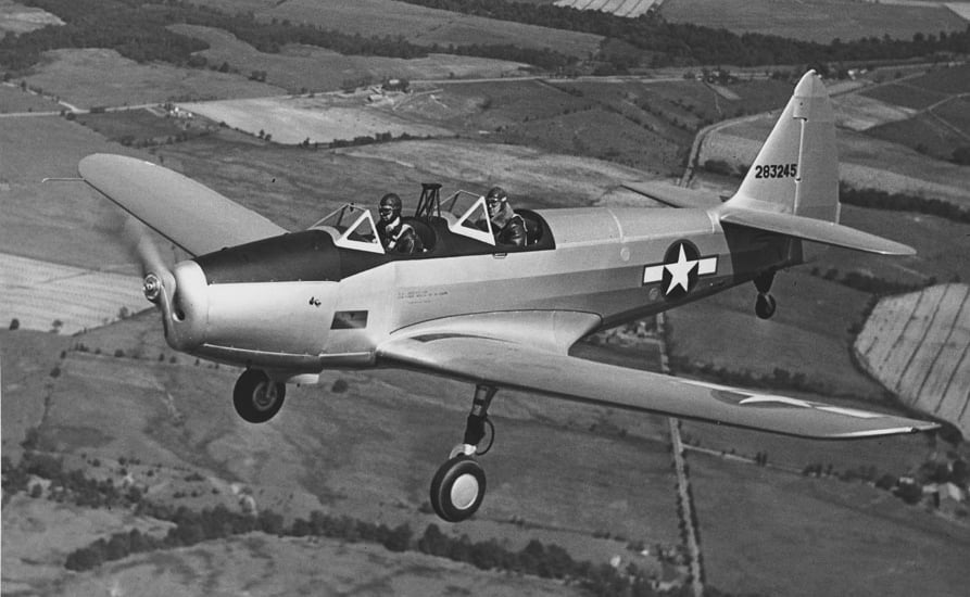
Despite entering service in 1940, the Fairchild PT-19 was very much a callback to aircraft of the late-1920s. The fuselage was made with steel tubing and the wings largely plywood. Because many USAAF bases were located in the South, delamination was a constant issue, damaging the PT-19’s otherwise stellar safety record.
Dr. Mike Elko, John’s uncle who took him up on his first flight, was killed on another flight in 1953 near Essex, Maryland.
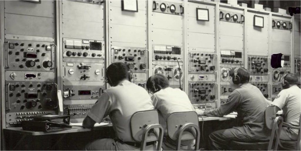
USAFSS operators in the operations building of an AN-FLR-9 station. The men pictured here are linguists intercepting radio telephone traffic.
There were nine AN-FLR-9 “Elephant Cage” systems – so-called because of their circular antenna arrays – scattered across the globe, monitoring Soviet and Chinese communication. It is very likely that John M. Elko, Jr. helped train some of the men pictured.
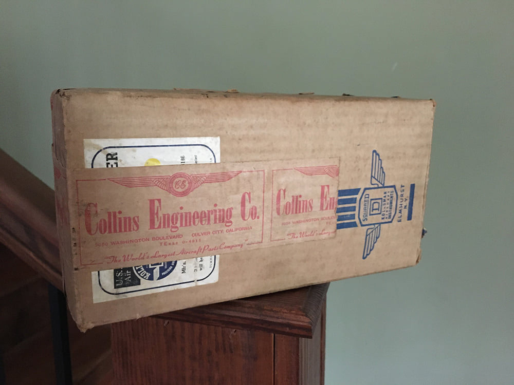
A close-up photo of the box in which the Type C-12 Altimeters were stored.
Photo taken 9 April 2022.

The Altitude Correction Card taped to one of the two Type C-12 Altimeters.
Photo taken 9 April 2022.
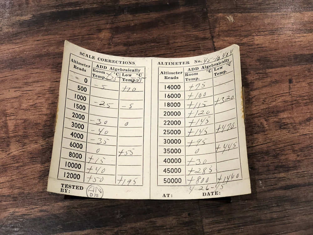
The inside of the Altitude Correction Card taped to one of the two newly-donated Type C-12 Altimeters.
We have already scanned and cleaned the card, so that future duplicates can be made.
Photo taken 9 April 2022.
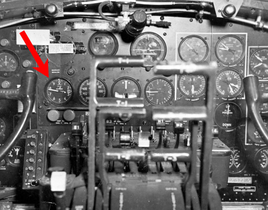
The cockpit of a Boeing B-17F of similar age to Lucky Thirteen. Based on the lights installed in this panel, this aircraft is slightly older.
The Type C-12 Altimeter is highlighted here.
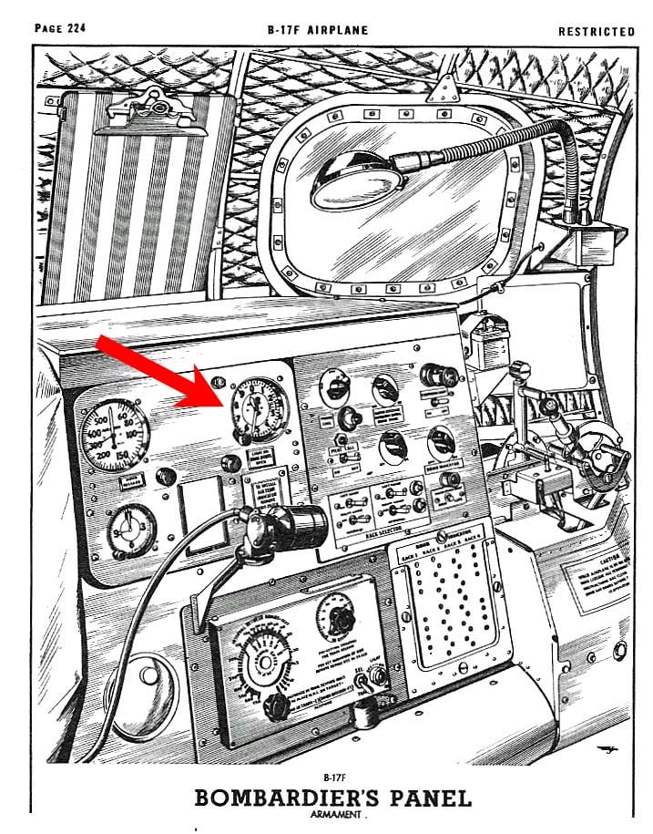
A manual illustration of the bombardier’s position on a Boeing B-17F. The layout of this position on Lucky Thirteen would have been identical.
The Type C-12 Altimeter has been highlighted. The bombardier’s panel provided a duplicate airspeed indicator, altimeter, clock, and if desired, air temperature gauge.
A few recent acquisitions:
First up is another Tuning Unit, the TU-6. The TU-6 is part of the SCR-287 Liaison radio system, being one of seven units. These units covered multiple frequency ranges and were used in conjunction with the BC-375 Transmitter. The TU-6 covered the 3000 – 4500 KC range.
The second piece is much smaller but infinitely rarer: the MC-163 Fairlead Clamp. This piece was donated by Joe McKowen off Gaffney, South Carolina and is part of the RL-42 Reel Antenna. The RL-42 served as a backup to the regular antenna line and could be reeled out using a small electric motor for better reception. The MC-163 fitted to the end of the F-10 Phenolic Pipe, which fed the antenna line in and out the airplane, and served to prevent the wire from snagging.
Having acquired these pieces, Hangar Thirteen has now completed acquisition of all the components to the SCR-287 Liaison System (the largest of the B-17’s radios). This is a massive step forward in our goal of historical fidelity.
All that is left to locate, in terms of radios are:
* BG-109-A Accessory Bag for Gibson Girl Emergency Radio
* Brass Tuning Cable for Fluxgate Compass
* 6-10754 (52.44 inch) Whip Antenna for Radio Direction Finder
* Two FT-115 Sway Mounts (currently using FT-167s as placeholders)
You can check out the details of the Boeing B-17F’s radio complement here.
We were also recently donated a set of three E-10 Edgewater Adapters from Jeff Martin of Caribou, Maine. The Edgewater Adapter was used in the B-17F’s waist, radio, and turret gunner positions, absorbing recoil via a large internal spring mechanism.
A common issue with surviving Edgewaters, these have been altered to suit the Browning M3 machine gun. Developed in the waning years of the Second World War, the M3 boosted the rate-of-fire from the standard AN-M2’s 650 round-per-minute to 1,200 rounds-per-minute, and was commonly found on early jet fighters like the North American F-86. While these Edgewaters are visually identical to unaltered examples, they are braced for a substantially higher rate of fire.
These three bring our current Edgewater complement to six, only needing one more for Lucky Thirteen. Three of our current Edgewater complement are unaltered, while three have been adapted for M3s. If the opportunity arises where we can trade the altered Edgewaters for regular ones, we might can be persuaded…
Still, this is a major step forward and a hardy thanks to Jeff for his donation!
The newly arrived TU-6 Tuning Unit.
Photo taken 6 April 2022.
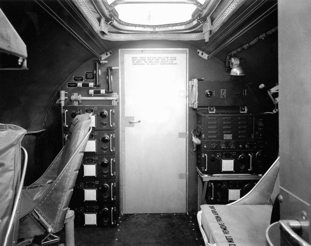
Bulkhead 6 aboard a Boeing B-17. This particular photo was taken on an E-model in the United States, as evidenced by the two passenger chairs – which were usually removed.
Note the stack of five tuning units on the left wall and the two on the right wall. Altogether, they covered frequencies ranging from 1500 – 12,500 KC, as well as 200 – 500 KC.

The newly donated MC-163 Fairlead Clamp.
Now to put together a working display for the RL-42 Reel Antenna…
Photo taken 6 April 2022.
SSGT Ralph E. Azevedo poses in his position as Left Waist Gunner aboard Qualified Quail (42-97851, 91BG). The RL-42 Reel Antenna Motor and Spool is highlighted here.
Damaged over Cologne, Qualified Quail crashlanded in Allied-occupied France on 14 January 1945 and salvaged. Azevedo was not with them, having been previously wounded and, upon recovery, transferred to another crew.
The newly-donated E-10 Edgewater Adapters.
They are in superb condition.
Photo taken 6 April 2022.
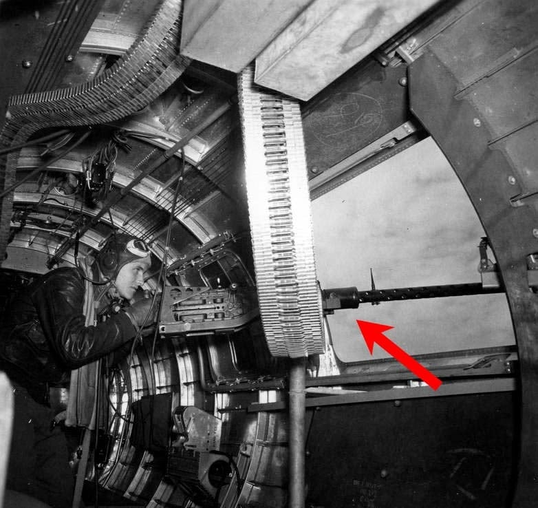
The right waist gunner on Hell’s Angels (41-24577, 303BG) poses at his position.
The E-12 gun cradle, which holds his AN-M2 .50 caliber MG, attaches to bolts on the sides of the Edgewater. The Edgewater is attached to the gun, wrapping around the cooling jacket. The Edgewater absorbs recoil by spring action, and was commonly found on gun positions exposed to the open air.
Hell’s Angels has the distinction of being the first Boeing B-17F in the US 8AF to complete her combat tour of duty. Being an early-F, her waist guns were originally can fed, but were later altered to use boxes mounted to the ceiling. An original ammo can, however, can still be seen here.
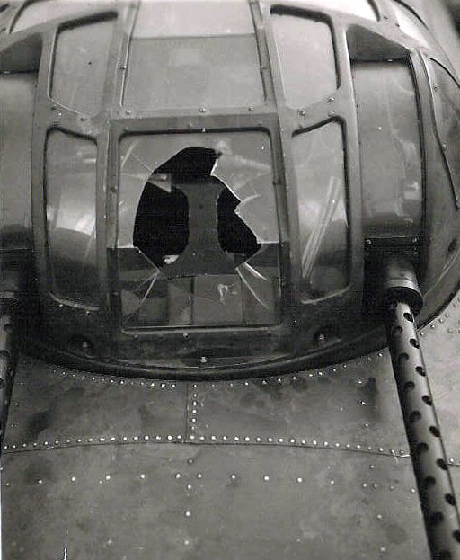
The top turret to Max (42-3158, 303BG). Shrapnel from flak punctured the plexiglass during the 14 October 1943 strike against Schweinfurt. Note the Edgewater adapters.
Like Lucky Thirteen, Max was a Douglas-built F-model B-17, and carried an Emerson Type 2 dome atop her Type A-1 Upper Turret.
Max was lost on a strike against Hanover on 29 April 1944, the aircraft exploding after enemy fighters knocked her two right engines. All but two of her crew were killed.
Photo taken 15 October 1943.
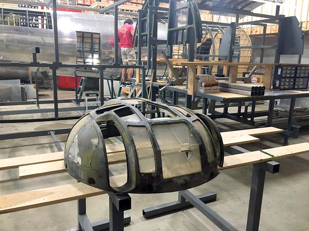
The Type A-1 Upper Turret dome that will be restored for Lucky Thirteen, sitting beside the fuselage jigs.
Photo taken 30 September 2021.
Some of you may recall the top turret hand controller we acquired in February of last year. This controller was an early variant found exclusively on Type A-1 Upper Turrets. After much subsequent research, we have determined that the latter variant is more accurate for our serial number. As such, we have decided to replace it with the latter hand control.
For those interested, here is the gist of our research:
(Warning, this is extensive)
While the US had experimented with remote gun turrets before the war – the idea being to create armament which would not compromise aircraft performance – the outbreak of hostilities, and the lessons of RAF BC operations, demanded immediate action. Efforts were already underway when a report filed on 1 July 1940 by LTC Grandison Gardner and MAJ Franklin Carroll resulted in the requirement that all US bombers be able to defend themselves from all four axes. Companies were assigned individual aircraft and Sperry Gyroscope was given the Boeing B-17.
Sperry was able to take fledgling technology originally developed for these remotes and quickly adapt it to create a locally controlled upper turret based on the UK’s successful Boulton Paul series. The A-1 Upper Turret was the US Army’s first mass-produced powered gun turret and was authorized for production on 9 July 1940. Originally, ventral defense was to be handled by a remote. However, tests at Wright Field found belly remotes unsatisfactory, no doubt due to the vertigo often suffered with such designs. A ball-shaped, locally controlled turret was suggested and Sperry complied, with authorization for the A-2 Ball Turret being given on 20 September 1940. Both of these turrets were patented on 24 October 1941.
Motor assemblies were made by the Sperry subsidiary Vickers of Detroit, Michigan, the same assembly being used on both turrets. Since Sperry was unable to handle the heavy casting and machining to mass-produce the turrets themselves, licensing was necessary. The companies chosen were, for the A-1, Steel Products & Engineering (SPECO) of Springfield, Ohio and, for the A-2, Briggs Manufacturing of Detroit, Michigan. SPECO completed its first prototype in November 1941 and began with an initial run of 11 production models the following month. Remote belly turrets would outfit the first 113 E-model B-17s until Briggs ball turret production was ready to take over.
SPECO and Briggs were later joined by Emerson Electric of St. Louis, Missouri. Emerson expanded their facility to include a dedicated turret division, which opened in January 1942, and since this had the potential to increase turret production from 250 a month to 1,000 a month, the Army pushed Sperry Gyroscope to reach out to Emerson. Emerson began A-1 production with a line of ten in August 1941, eventually reaching 100 a month a by the end of the year. It is unclear when Emerson supplemented production of A-2s, though it is clear this also occurred sometime in 1941. Emerson worked closely with SPECO to ensure compatibility, whereas Briggs was a somewhat more difficult partner.
There were three major variants of the A-1 Upper Turret – the A-1, the A-1A, and the A-1B. There was an A-1C but it never progressed beyond the experimental stage. According to the Boeing turret installation blueprint, we know that the B-17 transitioned from the A-1 to the A-1A with B-17F 42-30332. This aircraft was delivered in May 1943. Transition from the A-1A to the A-1B turret occurred with B-17G 43-38590, which was delivered in August 1944. Since the Boeing blueprint does not give information on Douglas and Vega-built aircraft, we do not know if they transitioned around the same times or not.
The Sperry Upper Turret Manual reveals that SPECO altered the design of the dome four times throughout production, while Emerson only did so once. Since only the first three domes were compatible with the A-1 series, we can likely identify SPECO serials SP-1 through SP-1640, and Emerson serials E-1 through E-2700, as Type A-1 turrets. (More on why this was so later.)
Since the Boeing blueprint explicitly references SPECO about the A-1B and not the A-1 and A-1A, it appears that Emerson never produced the A-1B.
Regarding domes, it should be noted that an important lesson was learned from the dome recently donated to Hangar Thirteen. While it has long been assumed that Type 1 and Type 2 domes were distinguished by the missing center bar on the latter, we now know that they were originally identical. The only distinguishing factor actually being who made which dome – SPECO for the Type 1 and Emerson for the Type 2. The removal of the center bar was clearly something added in the midst of Emerson production to increase visibility, akin to the much superior domes being put out by SPECO.
This information is useful in referencing wartime photographs. Looking at aircraft from the same production block as 42-30332 (Boeing F-100), we can see domes that only could have been fitted to A-1A Upper Turrets. However, since this was a Boeing block, we need to look at photos of Douglas-built F-models from the same production block as Lucky Thirteen (Douglas F-65). Doing so reveals that Douglas-built F-models were almost always equipped with Type 1 or Type 2 domes – indicating A-1 upper turrets even though SPECO had already switched production over to the A-1A.
We must also acknowledge that, like the B-17s themselves, the design of these turrets was never stagnant. An early A-1 was not necessarily identical to a later A-1. The very first page of the manual, for example, shows an illustration labelled as an A-1, with a base assembly that is usually associated with the A-1A.
So, let’s begin there.
The manual notes that the base assembly was altered to include an oxygen slipring with E-1851 and SP-1653. This alteration negated the use of a dedicated oxygen bottle between the gunner’s legs. Based on what we know from the domes, this means that SPECO built 13 A-1As before implementing the oxygen slipring. By contrast, Emerson built their last 849 A-1s with an oxygen slipring. Clearly the two companies were not in perfect alignment.
A similar situation occurs with the hand control assembly. Originally, the hand control featured a thumb wheel for adjusting the reticule on the gunsight. This was removed after E-1851 and SP-1202. Both of these serials were in the A-1 series. The new hand control used a motorcycle grip to adjust the reticule. This hand control also featured an intercom switch, removing the necessity for a foot switch on the base assembly.
So, if alterations were so fluid, what was the major difference between the A-1 and A-1A? It would appear to be the interrupter gear. The interrupter gear was redesigned so that the turret’s guns could be pointed below 5 degrees below horizon – something that the A-1 was incapable of. This is the reason that the A-1 could not use the initial three dome designs.
If I were to hypothesize what kind of upper turret was on Lucky Thirteen, I would assume the following:
Since we know that Douglas built F-models tended to have Emerson built A-1s, this confirms our usage of the recently donated top turret dome (which is an Emerson). However, since SPECO changed production to the A-1A somewhere around May 1943, it seems likely that Emerson would have begun using oxygen slip rings on its base assemblies around this time as well – almost certainly before July, the month that Lucky Thirteen rolled off the line. If so, this means that the base we have from Belgium (with its slipring) is correct for us. However, it also means that the hand control we have is incorrect and should be swapped for the latter model (as the hand control changed at the same time as the base assembly).
This would save us from having to deal with several oddball parts, such as the intercom foot switch and hand cranks for rotation and azimuth (E-1077 / SP-1276). It does not, however, save us from the most difficult part of all – the early-style interrupter gear. By limiting the serial range to the last 849 A-1s made by Emerson, the only alteration between our turret and the standard A-1 would be the addition of a seat-pad for the sling (E-1800 / SP-2261).
This is why we switched hand controllers.
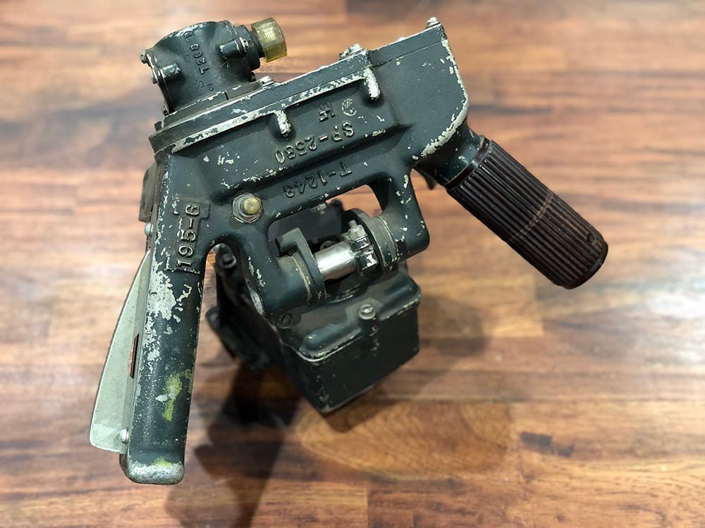
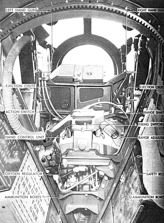
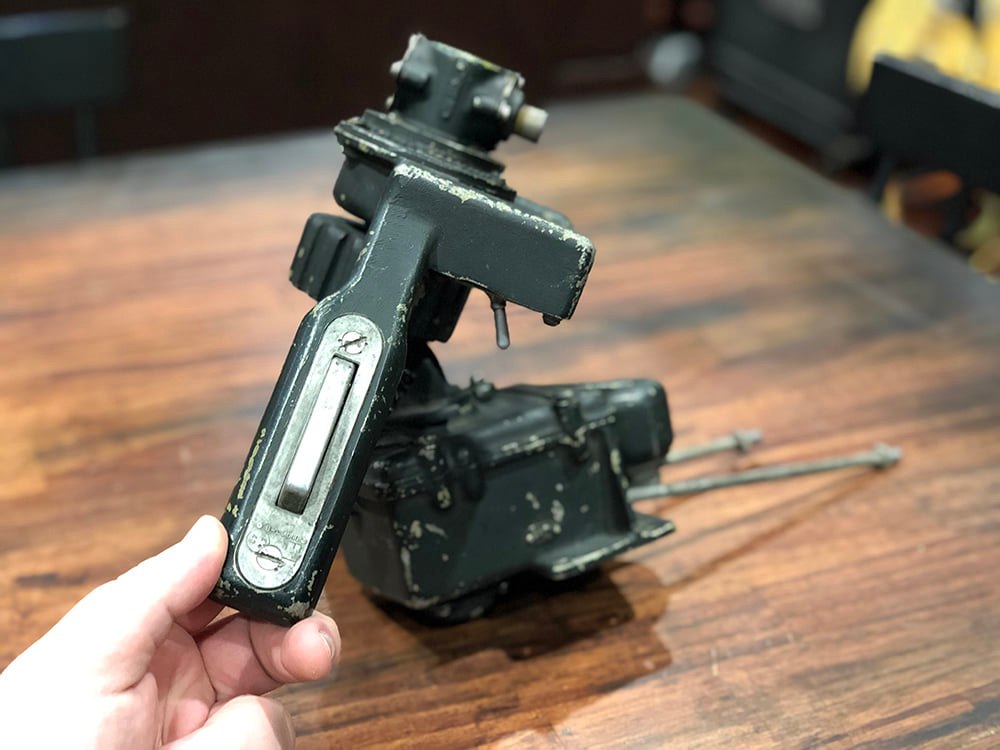
The newly arrived top turret hand control.
This type of hand control entered service with Emerson turret 1852 and SPECO turret 1203, and remained standard for the rest of the war.
Photo taken 28 March 2022.
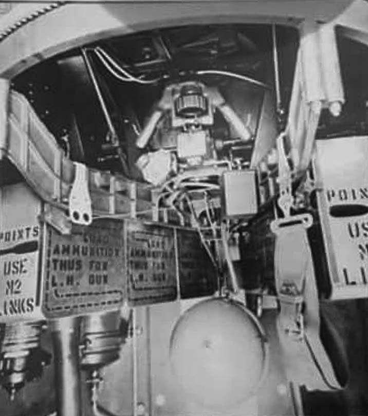
A manual illustration showing one of these hand controllers in place.
Judging by the lack of a pad on the gunner’s safety belt, this might actually be a Type A-1 Upper Turret. If so, then the dome above the camera must be a Type 3.
The earlier hand control used a thumb wheel for adjusting the reticule on the gunsight. The more common latter hand control, seen here, replaced the thumb wheel with a motorcycle grip.
A sophisticated analog computer, the turret’s gunsight calculated lead by having the gunner adjust the reticule to match the wingspan of the target. Gunners were required to memorize enemy aircraft wingspans, and this information was put into the gunsight along with the bomber’s airspeed.
The end result was that, unlike gunners using ring-and-bead sights, turret gunners could directly aim for the enemy knowing the that the sight had already calculated for drift.
Photo taken 28 March 2022.
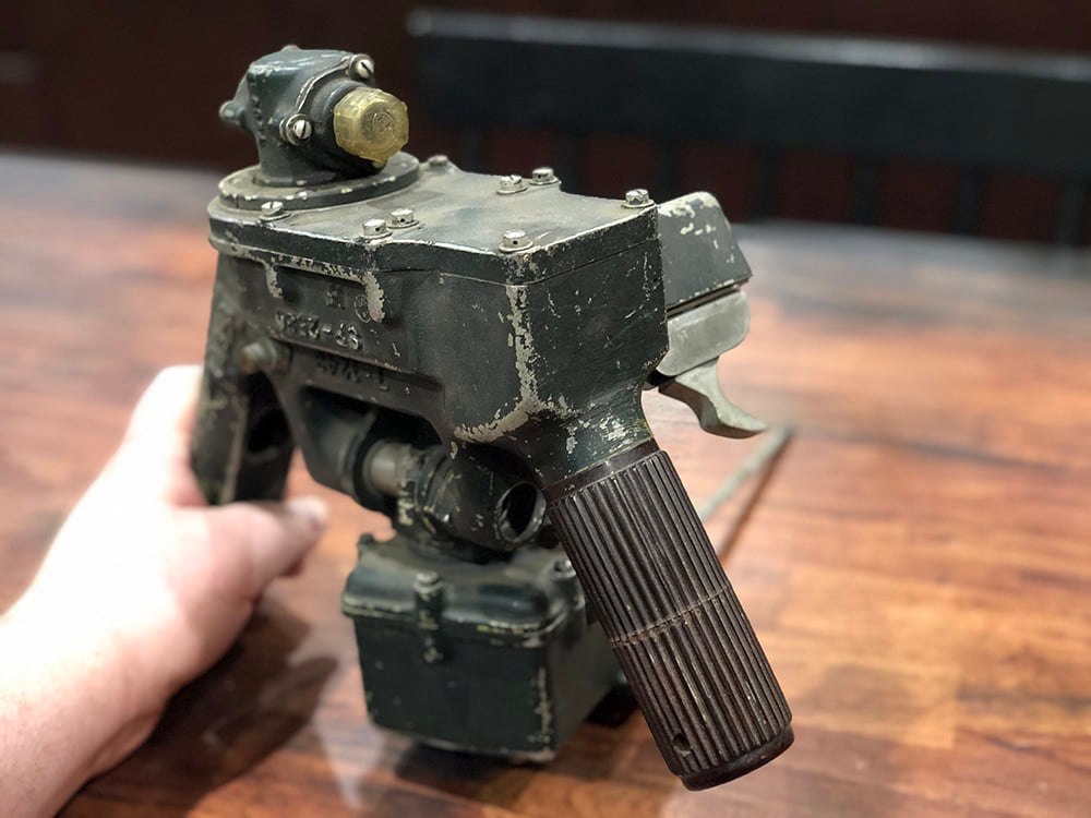
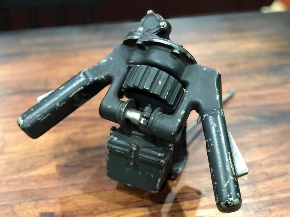
The triggers on the newly arrived top turret hand control.
My hand is on the dead man’s switch – without it being depressed, the turret will not move.
Photo taken 28 March 2022.
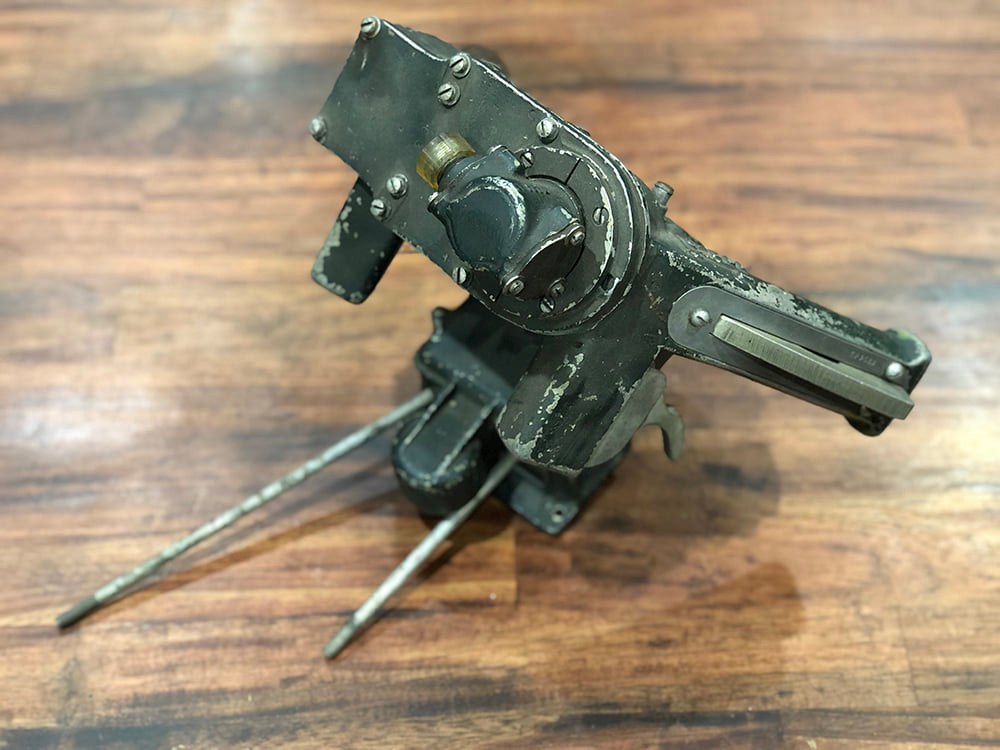
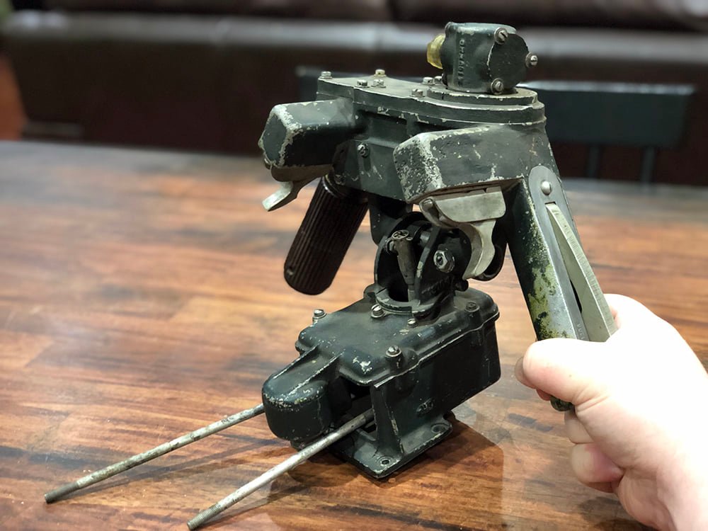
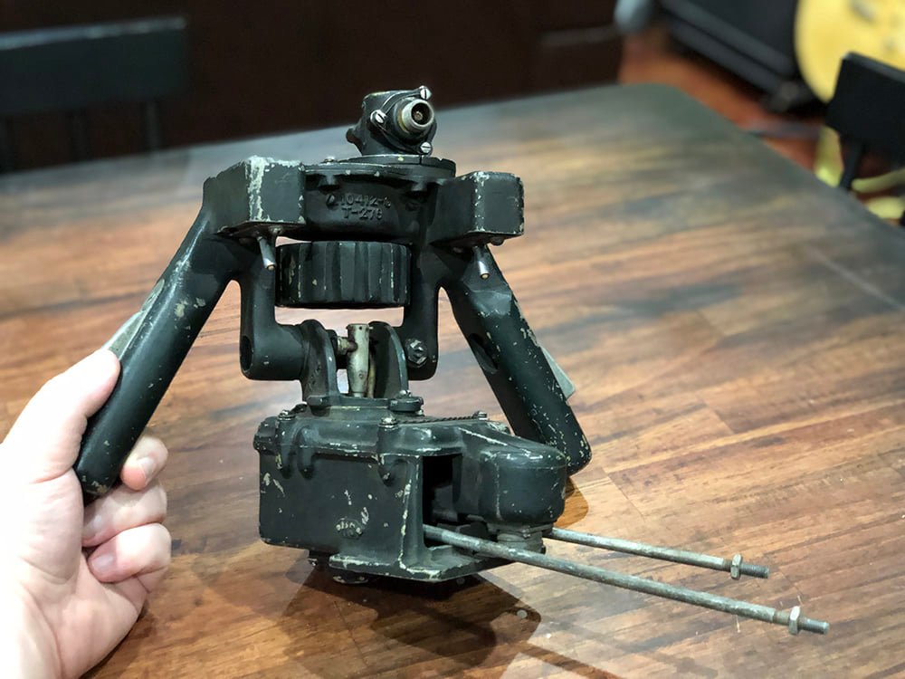
Top view of the newly arrived top turret hand control.
The levers sticking out of the bottom connect to the turret’s interrupter gear.
The interrupter gear prevents the gunner from accidentally firing into his own aircraft.
Photo taken 28 March 2022.
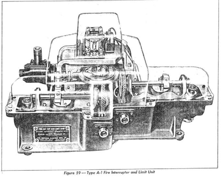
A cutaway illustration of the Type A-1 Upper Turret’s interrupter gear.
This will be one of the most difficult pieces for us to locate. We know of only one and it is being held for another project.
If any of you can help us locate an A-1 interrupter gear, PLEASE let us know!
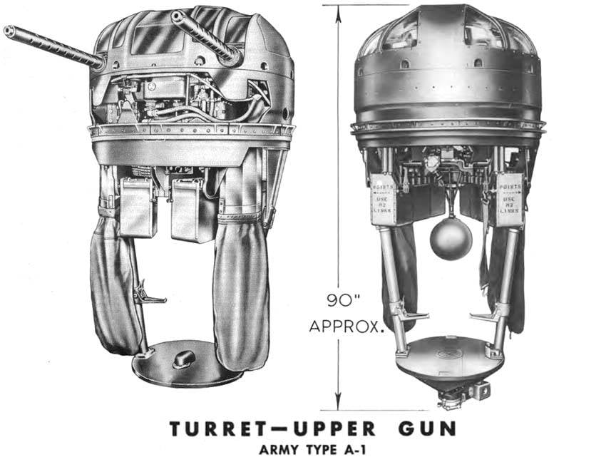
A manual illustration of an early A-1 Upper Turret.
Note the oxygen bottle. The bottle was mounted between the gunner’s legs and could be swiveled up to allow passage through when the turret was not in use.
The top turret control that we originally acquired for Lucky Thirteen.
Note the thumb wheel for adjusting the gunsight. Slow and clumsy, the motorcycle grip was a definite improvement. Also note the that the older control did not have proper triggers but spring toggle switches.
Photo taken 24 March 2022.
A composite made from a pair of manual illustrations. Despite being vastly different, these are both noted as being the same turret.
Like the B-17 itself, the layout of the turret was heavily dependent on timeframe of production.
The turret on the right is the older A-1. Note the oxygen tank and flat base assembly. The turret on the left is the latter A-1. Note the lack of an oxygen bottle. The bump on the base is the oxygen swivel, piping oxygen in directly from the airplane.
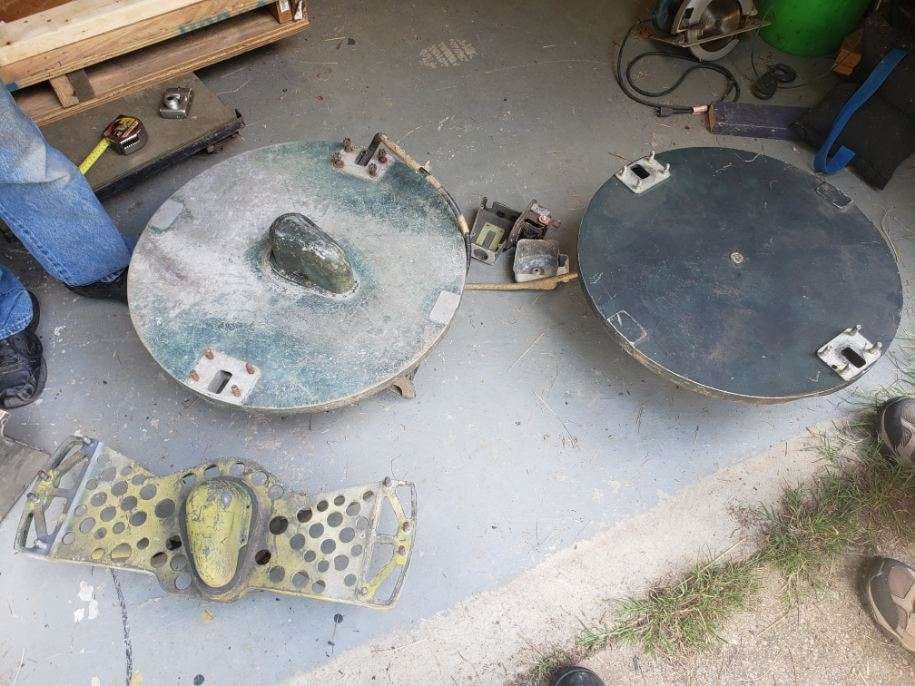
One of the coolest moments for turret nuts like Fred and me – all three base assemblies from the Sperry Upper Turret series are placed side-by-side.
The oldest base is on the far right. The center base is the one Hangar Thirteen acquired from Belgium last year.
The base on the left was designed by SPECO and was introduced with turret 4755 in the A-1A line. Meant to reduce weight, this base was slightly widened for the A-1B series later on. Emerson (who never produced the A-1B), never adopted this base, continuing to use the circular base throughout its entire run.
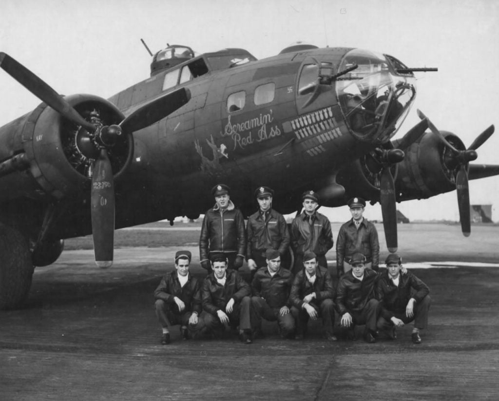
Screamin’ Red Ass (42-30340, 388BG), a B-17F from the first Boeing block with Type A-1A Upper Turrets. This photo clearly shows a Type 4 dome installed on the top turret, evidenced by the large lip atop the upper window. The Type 4 dome, designed by SPECO, was the first dome to make use of the new interrupter gear, which allowed the top turret gunner to depress his guns 5 degrees below horizon.
Screamin’ Red Ass arrived with the 388BG on 26 June 1943. Lucky Thirteen arrived with the 384BG on 11 August 1943.
Screamin’ Red Ass was shot down over Berlin on 8 March 1944 – the second US strike on the German capital. All but one of the crew (waist gunner SSGT Harry Quick) were killed.
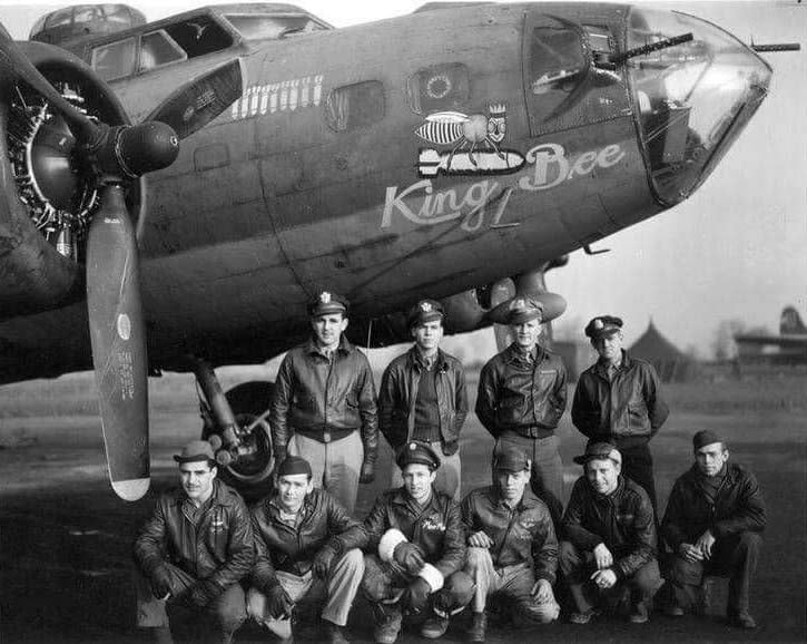
King Bee (42-3474, 100BG), a B-17F from the same Douglas production block as Lucky Thirteen. Note the top turret dome – it is a Type 2. The Type 2 dome, produced by Emerson, could only be installed on Type A-1 Upper Turrets.
While this production block (Douglas-65) was produced later than the one from Screamin’ Red Ass (Boeing-100), the Douglas planes are still using A-1 turrets.
King Bee was written off on 1 January 1944 after a crash-landing at Thorpe-Abbotts during a routine training flight.
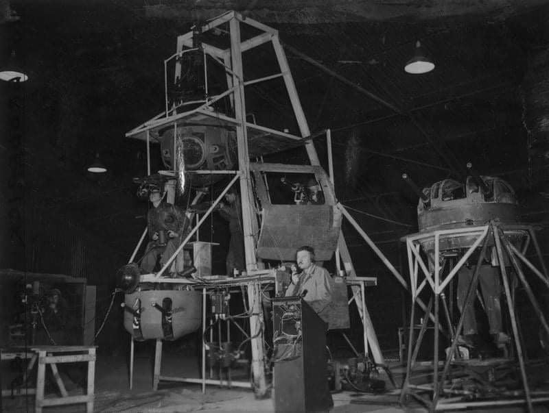
While the USAAF fielded some of the most highly trained personnel of the war, combat commanders were rarely satisfied with the quality of their new and replacement crews. CO 379BG COL Maurice Preston established a makeshift gunnery school for his men, using gun emplacements pulled from old aircraft damaged beyond repair.
Both the A-2 Ball and A-1 Upper turrets seen in this photo are accurate to Lucky Thirteen.
Note the A-1 turret on the far right. It has a Type 2 dome – which can only be used on an A-1 turret – but also has a base with an oxygen swivel.
Photo taken 6 April 1944.