
We have been so busy working that we have been forced to split this latest update into two parts!
This is Part Two.
Longtime followers may remember our friend Jack Antonio donated a massive amount of radio equipment to our project back in September. Included in this donation was a complete RL-42 tailing antenna system.
While the trailing antenna was rarely used in combat operations, the system was visually quite noticeable, sticking out of the left waist near the ball turret. A switch in the radio compartment activated a small motor, extending and retracting a spool of wire which dangled behind the airplane with the aid of a lead weight.
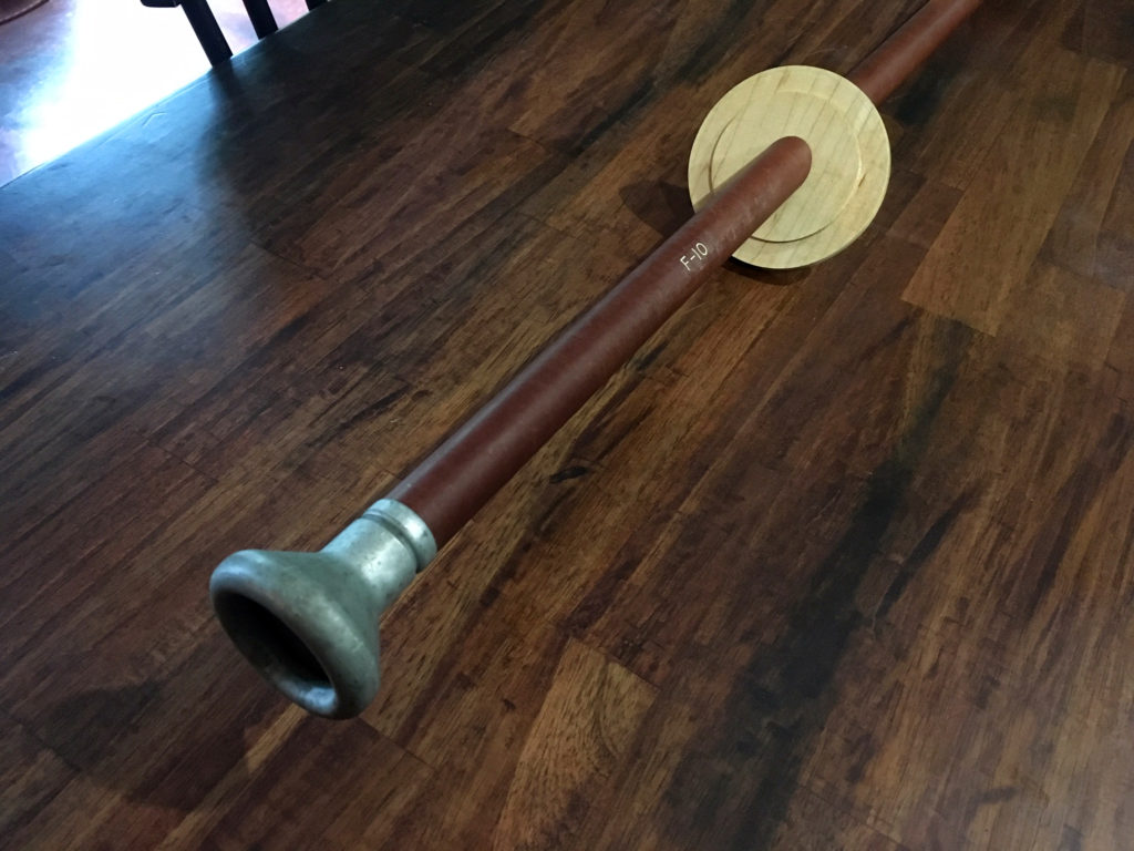
Judging from the flange piece which connects the pipe feeding the wire outside the airplane, Jack’s RL-42 was made somewhere around 1944-1945. This latter style flange used a wooden ball to hold the pipe, similar in size to a bocce ball. Lucky Thirteen, being an F model, had a different style flange. As such, we needed to replicate it.
The F-model flange was a piece of maple cut to a four-inch diameter, with the F-10 phenolic feed pipe passing through at a 35 degree angle. Having to purchase the maple for this, we also created the clamp which holds the completed assembly against the wall. Since both of these pieces were somewhat intricate, they were a perfect test for the new CNC machine.
I also took this opportunity to cut the metal bits for these pieces, so special thanks to Eric Miller for contributing the heavy aluminum for the clamp! While Ray is a metal wizard, this was my first time personally working with metal.
All that is really left to complete the reel antenna assembly is the MC-163 connector clamp which feeds the wire from the reel into the F-10 pipe. There are no blueprints for this piece so we need to keep an eye out for an original. If we can locate one we might be able to make replicas for others who need the same piece.
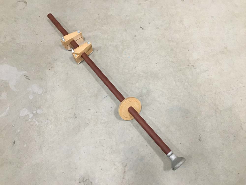
The newly-finished RL-42 reel antenna mount assembly sits on the floor of Ray’s shop.
Because it is so big, it is somewhat difficult to photograph.
Photo taken 2 July 2020.
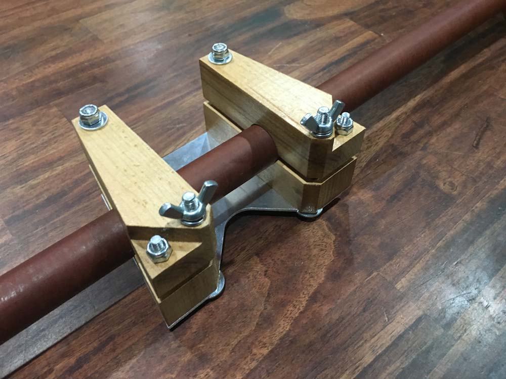
A close-up of the newly-finished clamp assembly.
Photo taken 1 July 2020.
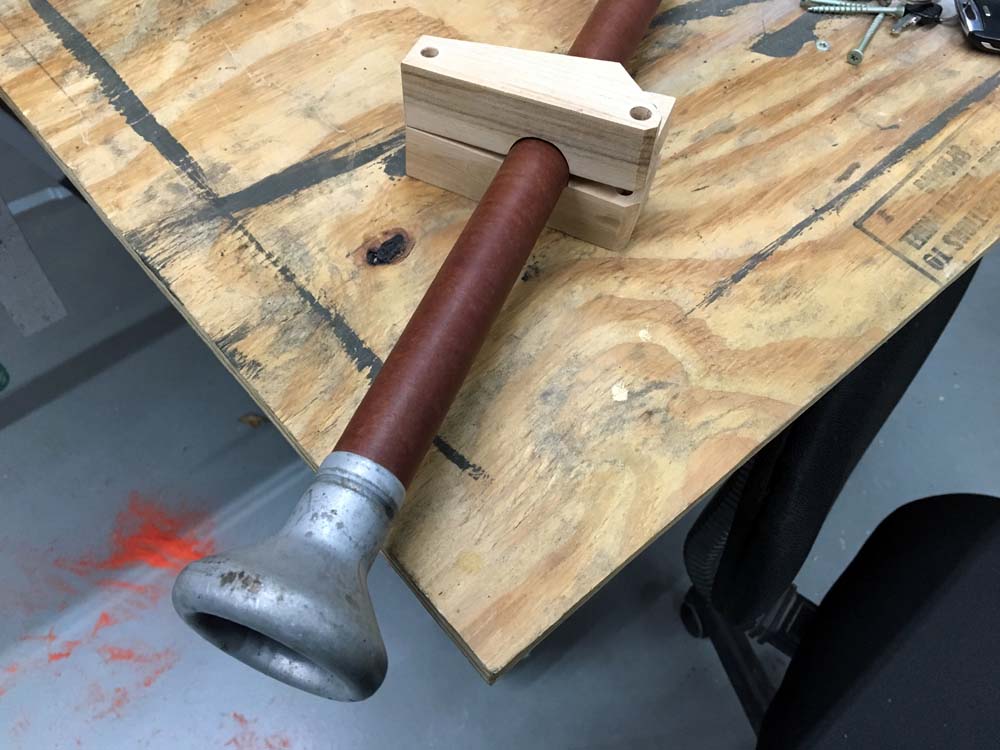
Test fitting one of the clamps.
Photo taken 24 June 2020.
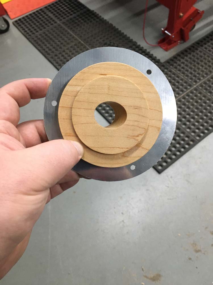
The newly-finished flange assembly.
The blueprints call for three DZUS fasteners: one 1/4 x .66 and two 1/4 x .62. Since I could not locate said fasteners in that size, the part was delivered without them.
Photo taken 1 July 2020.
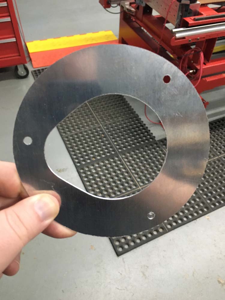
The metal piece behind the wooden flange.
Photo taken 1 July 2020.
The angled feed through the flange was difficult to cut and we are rather proud of how nicely it turned out. It fits like a glove.
While the cut angle was 35 degrees, the entire assembly will be angled 45 degrees inside the airplane.
Photo taken 22 June 2020.
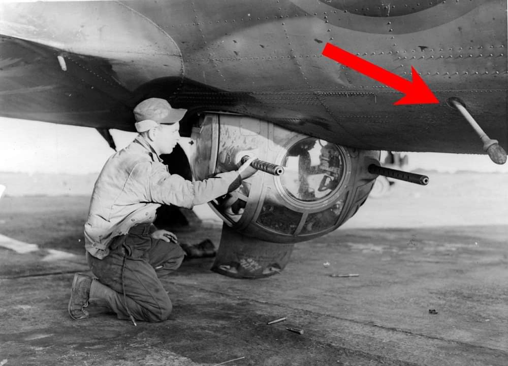
The reel antenna system is highlighted on this B-17F.
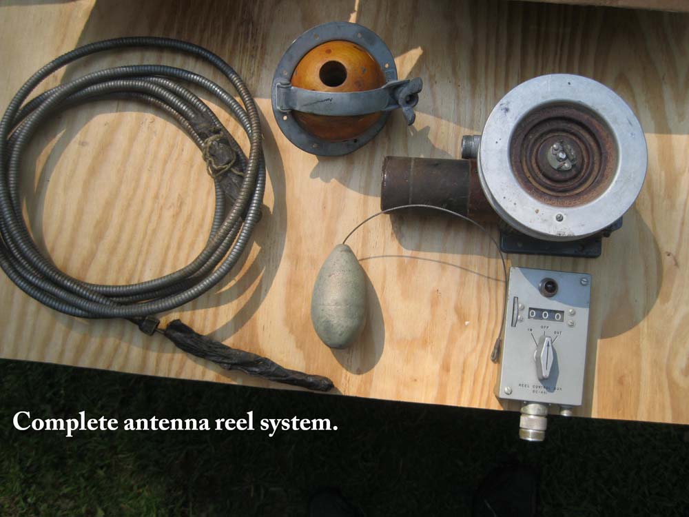
A pic Charlie sent over from when Jack donated his reel antenna system. There were more pieces than what is shown here, but you can clearly see the late-style ball flange.
Charlie recently replaced the wire reel with a NOS one. Aside from the MC-163 piece described earlier, the only other parts needed to complete the reel antenna are the ceramic beads which cover the wiring around this assembly.
Photo taken 3 September 2019.
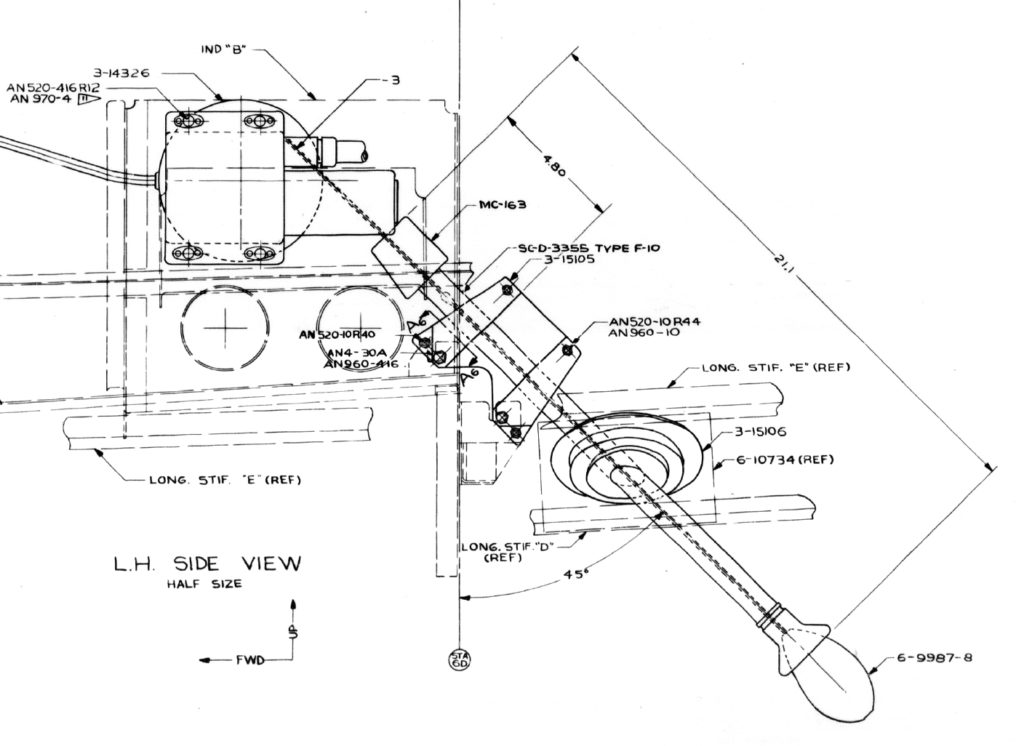
A close-up of the installation blueprint showing how the trailing antenna assembly fits together.
The elusive MC-163 connector clamp can be seen at the top of the F-10 feed pipe.
Had an awesome visit on 2 July 2020 with Peggy and Steve Burner, who came all the way from Oklahoma. Peggy’s dad was TSGT Leonard M. E. Nealis, flight engineer aboard Little America (42-30033, 384BG). Nealis was in the same unit as Lucky Thirteen – even the same squadron (546BS) – and as such, had a special connection to our project.
Lucky Thirteen and her crew were replacements, and as was common practice, her original pilot, 2LT Jacques E. Riddel, was made a co-pilot to a more experienced crew. 1LT Russel R. Faulkiner, an experienced co-pilot, was given Lucky Thirteen and commanded five of her seven combat missions.
Faulkiner was originally co-pilot aboard Little America, previously flying seven operations with her crew. Peggy’s dad witnessed his friend go down on 6 September 1943, and remembered the incredible shock of seeing Faulkiner return on 30 October 1943. Faulkiner was one of three from Lucky Thirteen to evade capture and return to the UK (the others being 2LT Harry A. Hawes and TSGT Oscar K. Hamblin).
Lucky Thirteen‘s original pilot, Riddel, was killed aboard Sky Queen (42-30032) on 28 July 1943 – his first mission.
Nealis flew his 25th and final mission on 5 December 1943 and was made a gunnery instructor upon his return to the States. Peggy recalled how her father never said much about the war, but noted that her bother made a concerted effort to write down everything they caught their dad revealing. Leonard Nealis passed away on 25 April 2008 at the age of 88.
Our heartfelt thanks to Peggy and Steve for their visit. They are wonderful people and it was truly special seeing the emotional connection our work had for Peggy. It is for people like you that we do what we do!
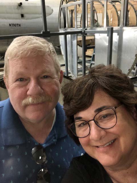
Peggy and Steve Burner.
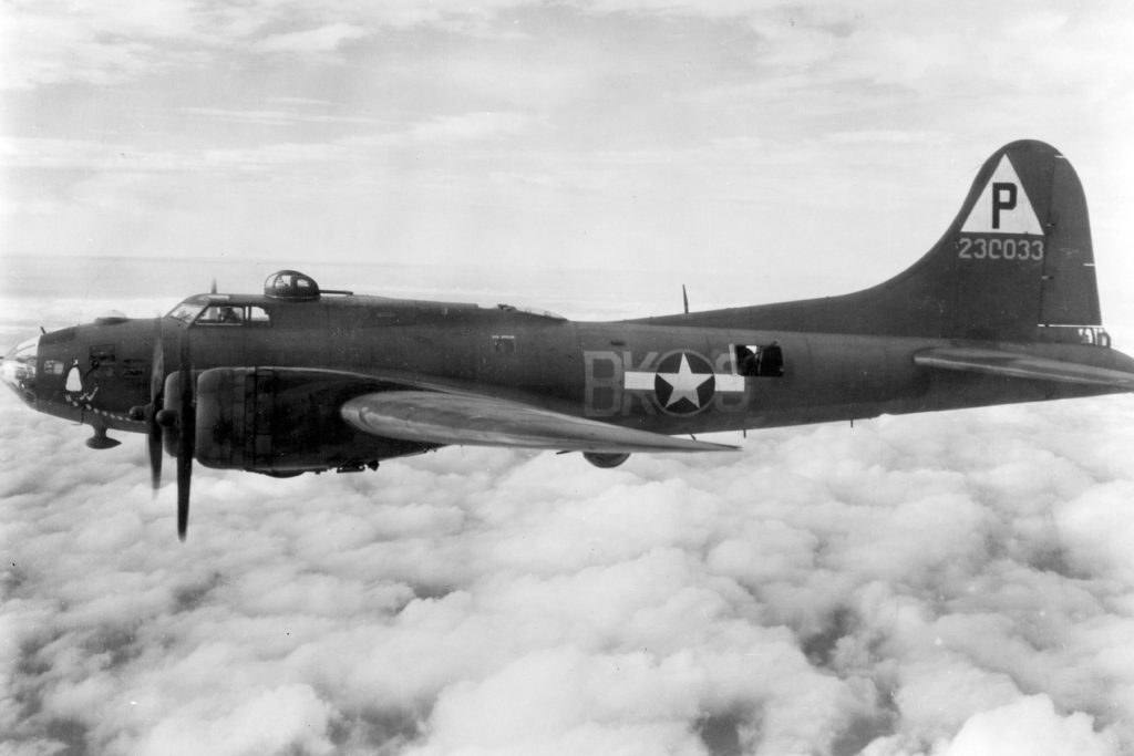
Little America (42-30033).
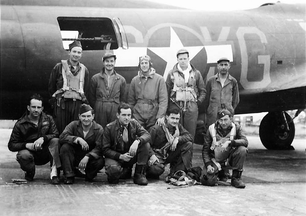
The crew of Little America.
Back row (left to right):
TSGT Leonard M. E. Nealis (Engineer/Top Turret)
SSGT Dennis J. Lane (Ball Turret)
1LT Sidney P. Taylor (Tail/Observer)
MAJ George W. Harris, Jr. (Pilot/ CO 546BS)
SSGT Roland L. Killin (Waist)
Front Row (Left to Right)
TSGT Jerome B. Beaupre (Radio)
SSGT Aloysius W. Mizgorski (Waist)
1LT Bill E. Blount (Navigator)
1LT James H. Kelly (Co-Pilot)
1LT John E. Ryberg (Bombardier)
Photo taken on 3 September 1943, after bombing the airfield at St. Andre-de-L’Eure, France (the secondary target). Little America flew as group lead – hence the crew arrangement above. Lucky Thirteen led the second element of the high squadron that day.
Eric Miller from Project Warbird came by over the weekend of 13 June 2020 to help rivet Station 4 together. In preparation, Ray took the time to clear coat the door and anodize the metal parts on it.
Special thanks to Steve Salinas for the donation of the Flight Reports Folder. Likewise, special thanks to Richard Boyens, Andrew Cathcart, Keith Ellefson, Joe Hall, Steve Heeb, Wayne Somerfield, Kevin Trotman, and Chris Wilkinson for their contributions toward the ALCLAD markings applicator. I hope you guys are as happy as we are seeing it all come together.

Photo taken 15 June 2020
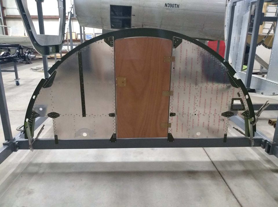
Photo taken 15 June 2020
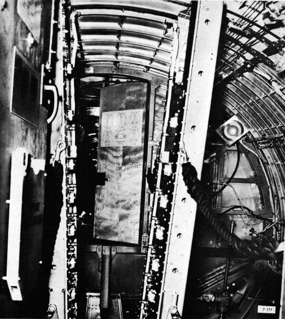
A rare photograph of the cockpit side of the Station 4 door as taken from an original manual.
This particular B-17 is a G model as evidenced by the oversize loading chart on the Station 5 door.
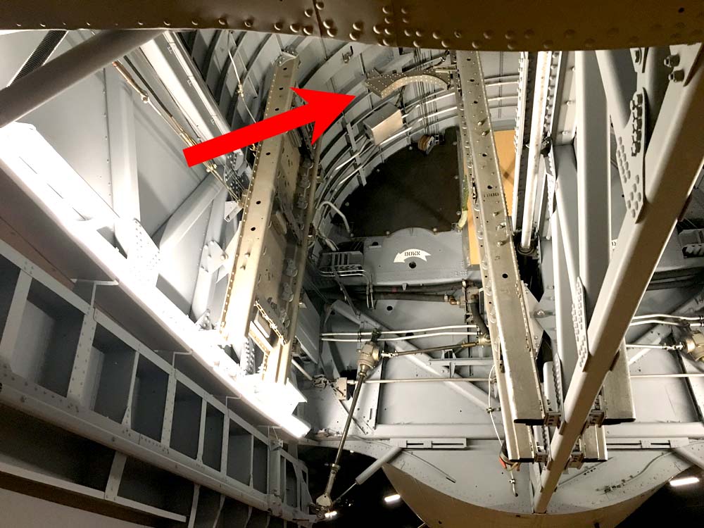
The bomb bay side of Station 4, taken from an original manual.
Two of the armor plates which go on this bulkhead can be seen here. An additional one is located on the opposite side behind the hydraulic reservoirs. The armor plates were made of .25 inch stainless steel.
The loading chart can be seen on the armor plate that hangs on the Station 4 door. Loading charts for the B-17 were located on either side of the bomb bay and instructed which points of the racks were rated for various bomb weights.
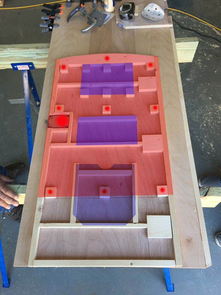
This photograph was taken while constructing the Station 4 door and shows the various hard points called for in the blueprints. It has been color coded to show what these hard points were intended for.
The charts which go on the cockpit side of this door were originally held in aluminum frames. We recently discovered that these frames stopped partway through the E series. This will require I make small alterations to the charts which go here for Lucky Thirteen and Memphis Belle.
With riots following on the heels of the virus scare, Erik Madsen up at Harvard has not been able to make much progress on the instrument panel and box frame. However, since we now have access to a CNC machine here at the woodshop, we figured we could go ahead and move forward on the panel face and let Erik handle the more complex box frame.
My wife Megan (who is a graphic designer) laid out the template using the original blueprints as a reference. Karl offered advice on the top arch as, like you modelers know, Station 3 is not actually a full circle. By laying out everything on the computer and transferring it to the CNC, we can ensure that the placement of each gauge matches the prints down to the .001 point. And, because everything is saved on the computer, we can make multiples if necessary.
However, it is important to remember that the blueprints were originally drawn by measuring a finished example. As such, we occasionally run into blueprints where the numbers do not match one another. To counter this, we are going to use a plywood mock-up to ensure proper fit before moving on to the phenolic (which was the panel’s original material). If we have to make any changes to the template, better to find out before cutting the phenolic!
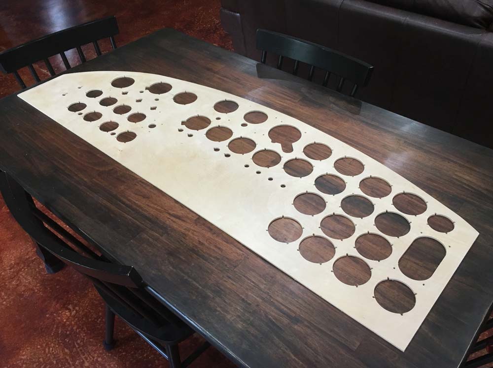
The panel mockup is laid out on my dining table.
Since this mockup is just for testing, we didn’t bother cutting it into three parts yet.
Photo taken 9 June 2020.
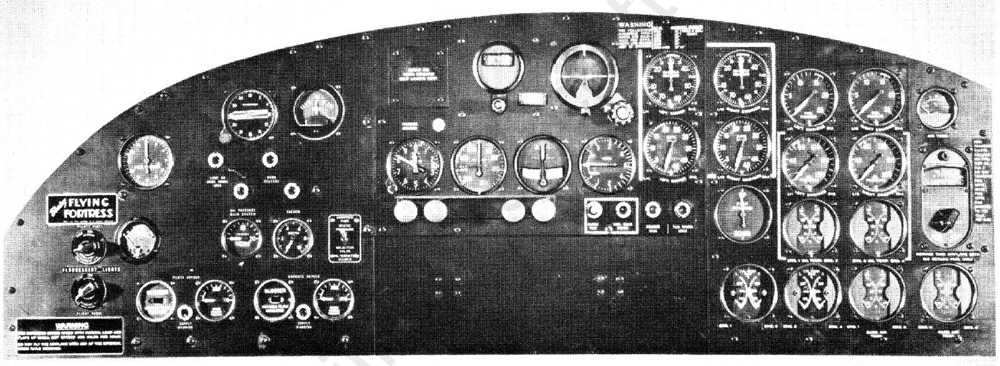
A wartime photo of a training instrument panel. The panel for Lucky Thirteen only differs from this one in having an Emergency Oil Pressure gauge.
If you look closely, you can see the three panel sections which make out the full panel. The blank section will later be obscured by the center console.
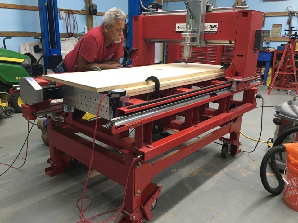
My Uncle Glenn watches as the CNC machine in our woodshop starts cutting.
We started cutting around 6pm and it finished just after 2:30am.
Photo taken 8 June 2020.
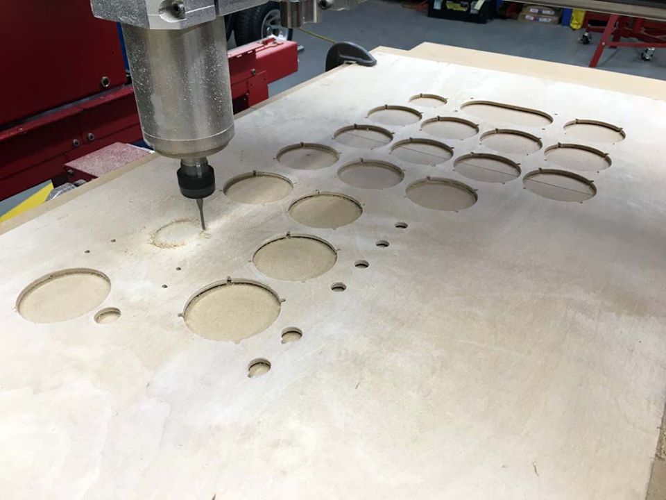
The CNC machine starts to cut out the Artificial Horizon sometime shortly after midnight.
We set the machine to run on its slowest setting to keep the wood from splintering. The bit cut so fine that all that came up was a fine dust.
Photo taken 9 June 2020.
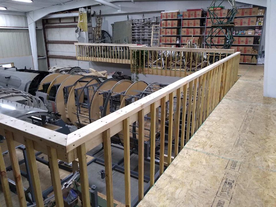
Over the weekend of 5-7 June 2020 Ray finished the walkway connecting the two recent upstairs portions. He also installed the drywall below the walkway. Sometime in the future I will have to share pics of what this hangar looked like before we moved in. It has come a LONG way.
The next step will be to install the drywall upstairs and build a balcony extending over the fabrication area. Along with making more room for storage and displays, the next upstairs extension will feature a small seating area. The radio system displays will also be moved to the balcony you see here, giving more room for demonstrations.
That said, we are not yet at a point where we can take in many visitors. Asheville Regional Airport requires a camera for any hangar door that does not pass through a security checkpoint. These security systems must be paid by the hangar occupant and, naturally, the amount of money they charge is outrageous. As such, we will continue just checking people in through the gate. If you want to visit, be sure to call ahead so we can buzz you in.


It’s peach season in South Carolina so if you go out and buy peaches, make sure they’re from here. We are the peach capital – not Georgia!
Speaking of “peaches” – we got some wild donations:
Long time 384BG friend Matt Smith sent us some incredible pieces all the way from England. These pieces were originally located by Grafton Underwood resident Quentin Bland, to whom Matt was a longtime protégé and friend. Quentin grew up there and was a regular sight at the base, after the war becoming one of the 384BG Association’s most beloved members. We are honored that Matt shared some of Quentin’s pieces with us. Not only do they pay homage to this beloved man, but they are precious to us as pieces from the same unit as Lucky Thirteen.
We were unable to identify the first piece that arrived (a black pump assembly) but the next two pieces were identified as brackets for the B-17’s bomb bay ferry tanks. These auxiliary fuel tanks held 410 gallons each and, when combined with the inner wings’ 1,700 gallons and outer wings’ 1080 gallons (also known as “Tokyo Tanks”), gave the B-17 some 3,600 gallons of fuel.
Of course, using the auxiliary tanks meant foregoing any bombs. These tanks were usually used on ferry flights from the US to assignments overseas. Outside the B-17, ferry tanks saw combat in early-attempts to improve the range of the Republic P-47 and by Consolidated B-24s during Operation TIDAL WAVE. These brackets are extremely rare as they were most commonly seen on F-models, being phased out of the G series in March 1944.
Another donation this week came from our friend Jack Antonio down in Warner-Robbins, Georgia. Learning of the trouble we had in finding the FT-115 Sway Mounts for the BC-375, Jack donated a pair of FT-167 mounts. While the FT-167 is designed for another radio on another aircraft, it is identical to the FT-115 in every way except weight rating. With this problem solved, the only pieces that remain to complete the massive SCR-287 Liaison Radio system is a TU-6 and TU-8 Tuning Unit.
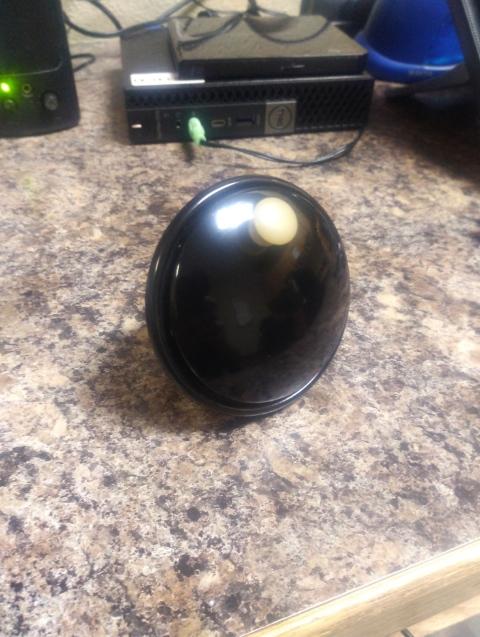
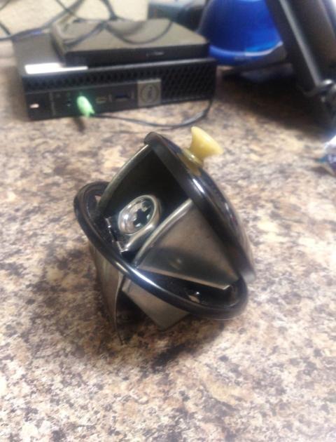
Lastly, we received a Type A-11 Clock from Steve Olson of Renton, Washington. Steve’s dad, Arnt, was a mechanic with the 2AF and a B-17 nut. This clock was pocketed from one of his aircraft. Steve donated the clock in his dad’s honor saying his “father smiles today.” A beautiful sentiment that is greatly cherished.
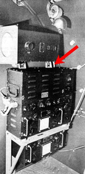
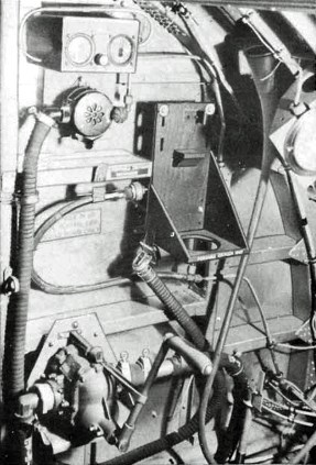
The A-11 is what was known as an “8-day clock” in reference to how often it requires winding. This A-11 appears to be in need of repair as the winding mechanism is inoperable. Hopefully we can find someone local who can repair it. This clock was mounted on a small panel on the cockpit roof next to the primary compass and aircraft thermometer. Said thermometer – a Type C-11 – is all that is left to complete this panel.
A very special “thank you” to Matt, Jack, and Steve for these incredible donations!

Matt Smith’s ferry tank brackets beside the newly cad-plated carry-thru spar plates.
Both of these brackets will be installed into Lucky Thirteen, though one will require a few of parts be replaced due to corrosion.
Photo taken 2 June 2020.
The ferry tank brackets are highlighted aboard Memphis Belle at the National Museum of the US Air Force.
As far as we know, the Belle is the only surviving B-17 to still have these brackets, though Homesick Angel at Offutt AFB still has visible holes showing where her brackets used to be.
Photo taken 24 August 2018.
An illustration from the Parts Manual showing the auxiliary fuel tanks installed.
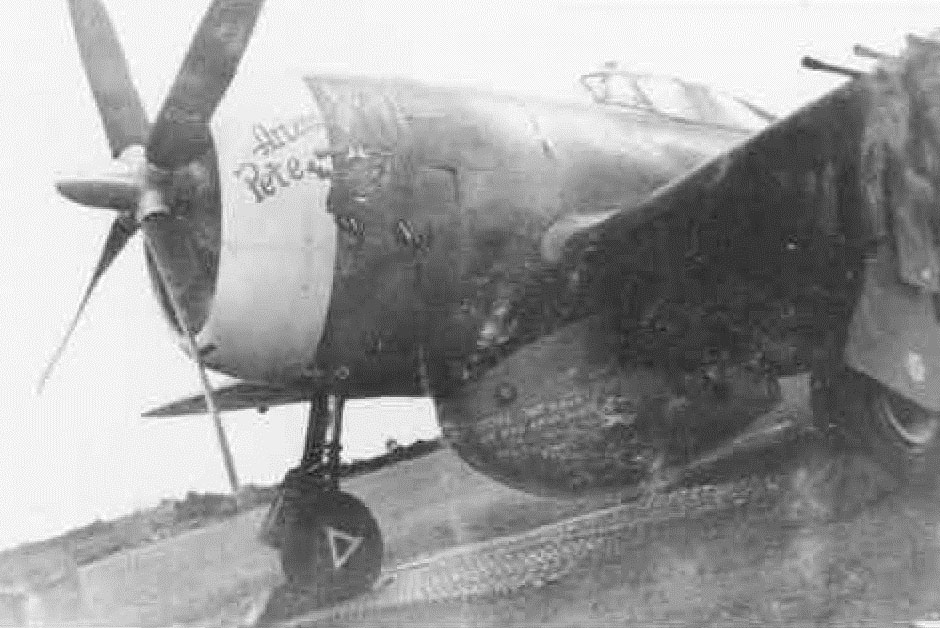
Republic P-47C Arizona Pete (41-6539, 4FG) with a 205 gal. ferry tank.
The first use of external fuel tanks on US 8AF escort fighters occured on 28 July 1943, with 123 P-47s escorting 302 B-17s on a strike against the Fieseler Flugzeugbau (Fieseler Aircraft Construction) plant of Kassel and the AGO Flugzeugwerke (Aviator Gustav Otto Aircraft Works) of Oschersleben, Germany. Struggling to increase fighter range, 8AF P-47s were already being altered to carry auxiliary fuel tanks in their fuselages. External fuel tanks were an uneconomical but effective solution, as the fighters could simply drop the extra flammable weight whenever entering combat – hence the name “droptanks.” Crudely altering the P-47’s gigantic 205 gal. ferry tank – which was not designed for combat usage – so that it could be jettisoned, US fighters penetrated German airspace for the first time this day. Since these droptanks lacked pressurization, they were only half-filled and were immediately dropped upon reaching “feet dry” (crossing the French coast).
Despite the ad hoc nature of this day’s escort, the result was undeniable – more German interceptors were shot down than on any prior strike (23 fighters). For comparison’s sake, the highest interception loss prior to 28 July was 17 May, with 16 German fighters destroyed. This trend continued on 30 July, again using ferry tanks, downing an incredible 31 German fighters. The first purpose-built, pressurized droptanks entered service on 12 August 1943.

The pump assembly Matt donated. Going through our books and asking friends, we cannot identify this piece. The larger tag is marked by “Black & Decker,” a company not listed as a Boeing supplier – though this is not uncommon.
Photo taken 1 June 2020.

Jack Antonio’s newly-donated FT-167 Sway Mounts.
Photo taken 30 May 2020.
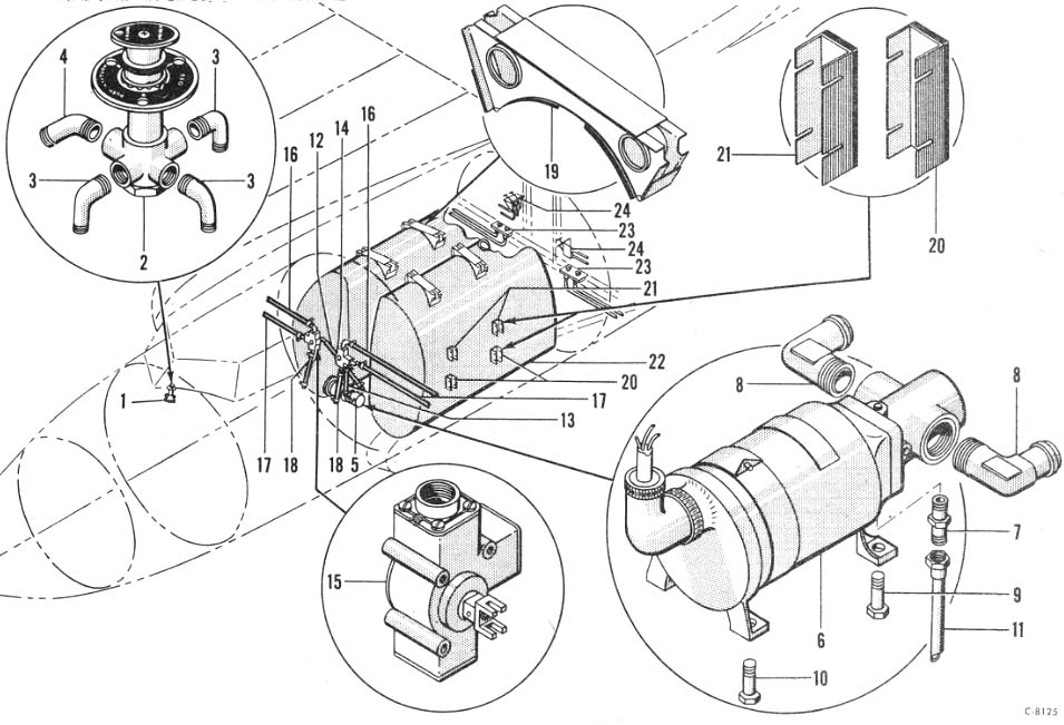
The FT-115 Sway Mounts are highlighted in this manual photo.
These mounts keep the BC-375 transmitter from swaying in flight and provides additional support to the BC-306 Tuning Control above.
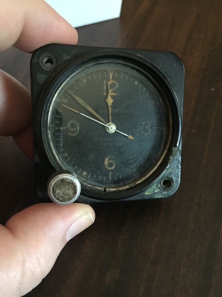
Steve Olson’s newly-donated A-11 Clock.
Photo taken 3 June 2020.
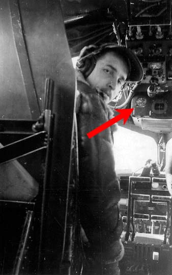
This photo from the 384BG shows Charles W. Tennant at the controls of a late-B-17F – distinctive for its ceiling-mounted emergency brake levers.
The A-11 clock has been highlighted.

Steve’s father, Arnt (left), at work on a B-17.
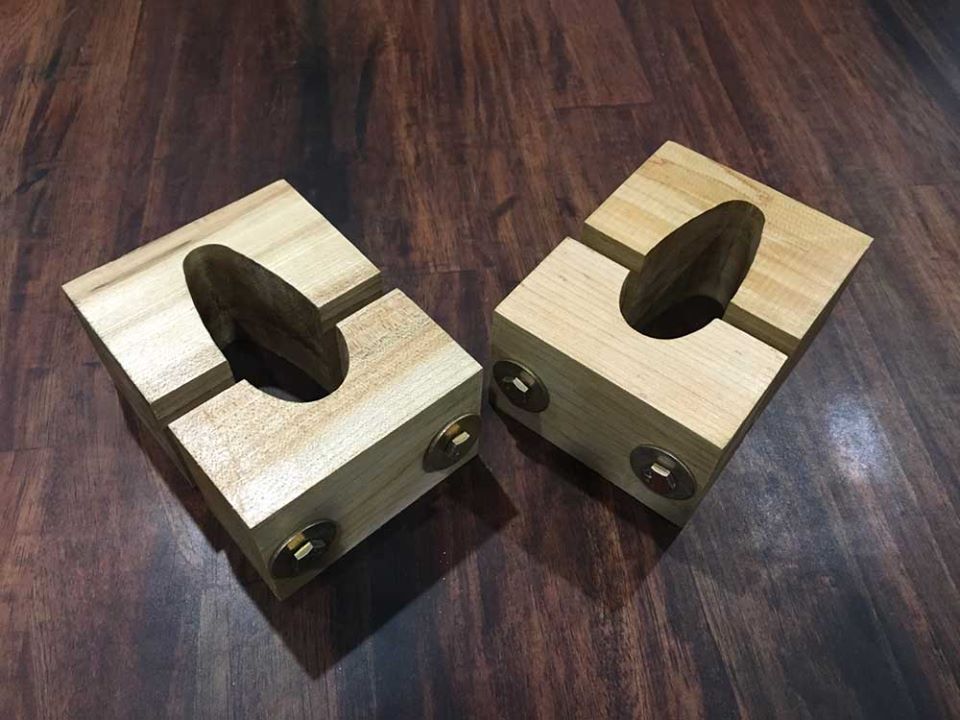
Some of you may recall that we created a set of VHF Antenna Clamps back in early-2019. Well, there was an issue with them – the wood grain was facing the wrong direction. While that may not sound like a problem, it was something that could become an issue in the future. You see, having the screws facing the same way as the wood grain meant the clamps could eventually split. We needed to make new ones.
Rather than cut them by hand again, this time they were cut with a CNC machine. My dad has long wanted one so he recently purchased a machine from Legacy Woodworking. While it is an expensive investment, it is also something can be a huge help in the future. We are slowly learning how to operate the CNC and these clamps are its first contribution to Lucky Thirteen. The fit is far better than anything we could have done by hand.
In other news, our friend Chris Ely sent over some pics of a 1936 Ford Ashtray he just finished restoring – the first of four that will go in Lucky Thirteen. Chris is actually working on a project of his own in Branson, Missouri, restoring a vintage fire truck. Chris has been an amazing asset to us, as not only has one of his contacts begun making boots for the pilot’s control columns, but Chris is also restoring a pair of Type A-2 Carbon Tet Fire Extinguishers for Lucky Thirteen. We cannot thank him enough!
Lastly, attached is another 3D mockup, this time of the Type A-6 Bombardier’s Lamp. The NMUSAF Restoration Division was kind enough to send us a series of measurements and photographs of the one that will be installed on Memphis Belle last year. If anyone out there wants to take a crack at replicating this lamp, we have a gooseneck and a dome to help you get started.
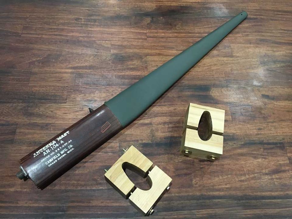
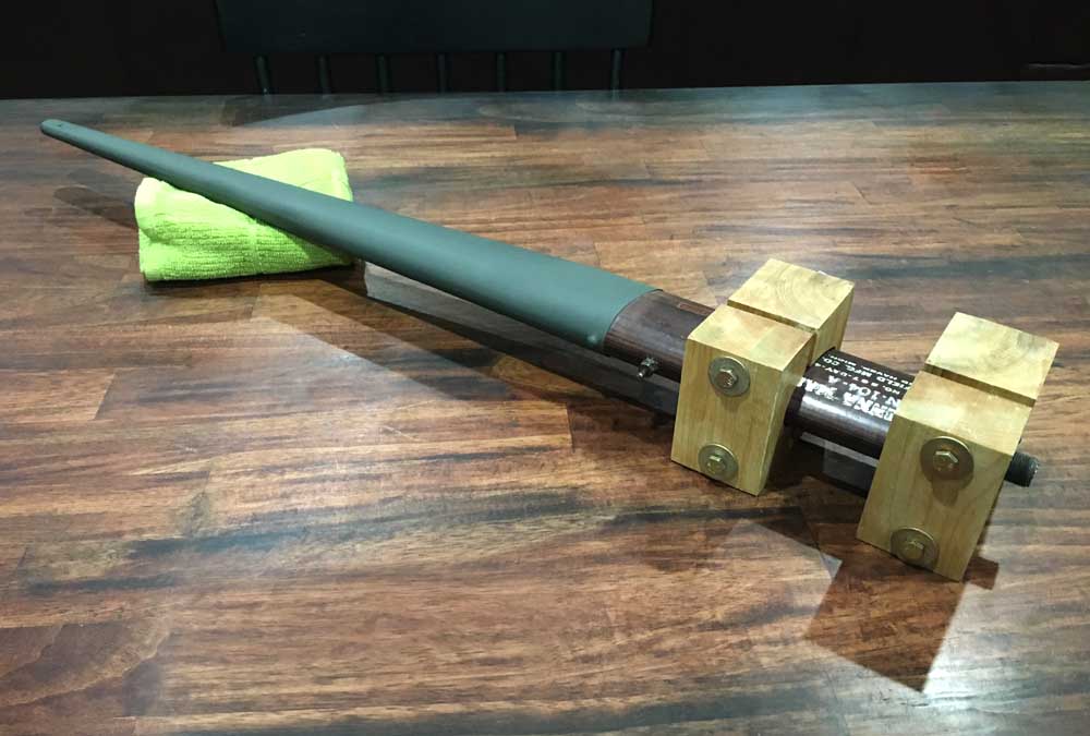
The newly-finished clamps sit beside the AN-104 antenna where they will be eventually mounted.
The mast was made by Camfield Manufacturing of New Haven, Michigan (a kitchen utensil company) and came in three variants: Army, Navy, and postwar replacement. This is an original Army variant.
Photo taken 20 May 2020.
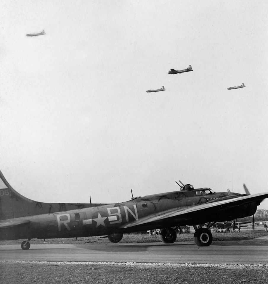
Knockout Dropper (41-24605, 303BG) taxis to hardstand on 13 November 1943. Her VHF antenna is visible center fuselage, left of the radio hatch gun.
A line-of-sight system, the VHF was a quick and easy method of short-range communication.
Knockout Dropper holds the distinction of being the first 8AF aircraft to complete 50 and 75 combat missions, accomplishing this on 16 November 1943 and 27 March 1944, respectively.

SSGT Roland Downs adjusts the radio mast on Heaven’s Above (42-97328, 388BG).
The clamps are attached to the VHF antenna.
The clamps are made of hard maple, a heavy and dense wood that is rather expensive in such thicknesses.
Photo taken 20 May 2020.
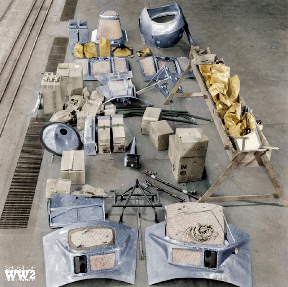
A shot from Daniele Salieri’s “Ghosts of WW2” colorization series featuring the United Airlines Modification Center in Cheyenne, Wyoming. The VHF antenna is located in the center of the photo.
VHF systems were introduced by the British and had to be added to US bombers prior to heading overseas. A wooden shelf held the VHF radios near the ball turret position.
The VHF antenna clamps are lacquered to prevent any possible condensation from eroding the wood.
Photo taken 20 May 2020.
Chris Ely’s recently restored 1936 Ford Ashtray.
Photo taken 21 May 2020.
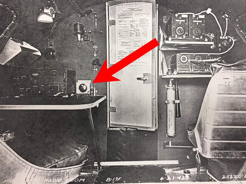
The radio operator’s ashtray is highlighted aboard an early-B-17F.
This particular B-17F is identical to the setup aboard Memphis Belle, though the auxiliary seats to the right were removed.
Photo taken 21 June 1942.
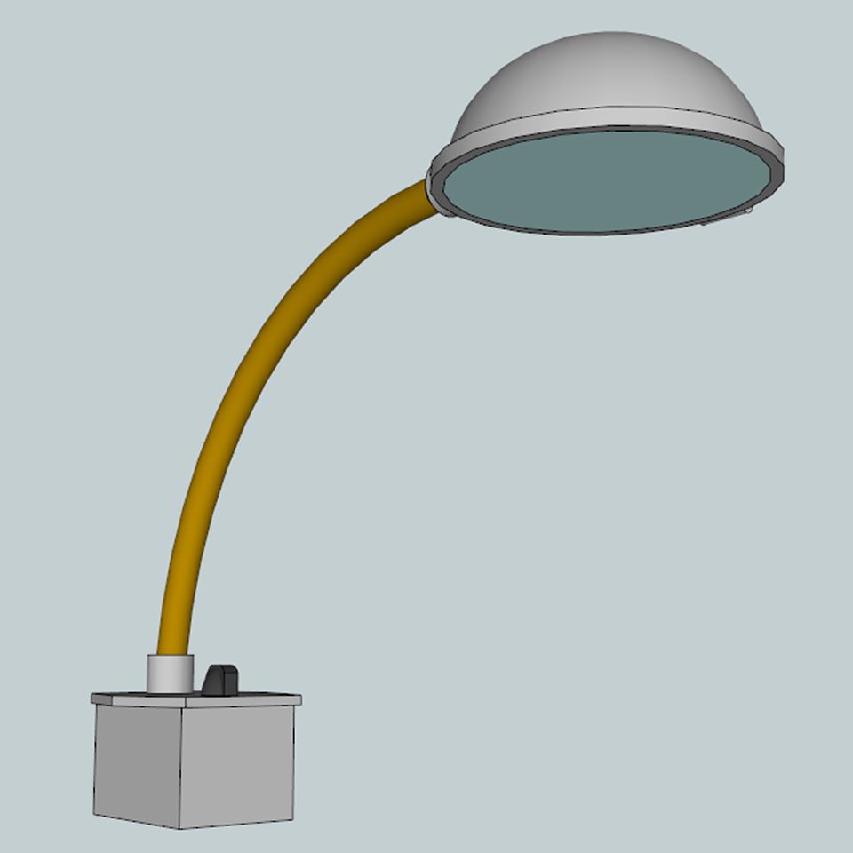
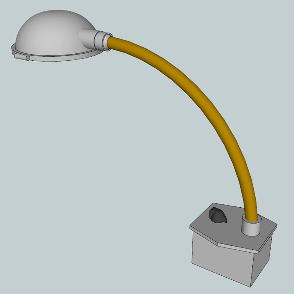
The 3D mockup of the Type A-6 Bombardier’s Lamp.
In wartime these were made by Olympus, a producer of laboratory equipment.
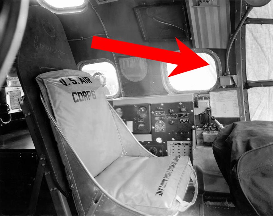
The Type A-6 Bombardier’s Lamp is highlighted in this B-17E’s nose compartment.
Ray recently had some parts cad-plated for the bomb bay. We were fortunate here as, with a couple minor exceptions, all of the bomb bay bracket plates are originals. All that was needed was to simply clean and refinish them.
Going over these pics, Ray asked if I would put out an appeal for the B-17’s cockpit fuse box. He had seen an original example (from a G-model) sold online and hoped that there might be an F-model example out there, too. Since I was not as optimistic as Ray, I went ahead and put up the blueprints relating to the fuse box. They are on our website under the Instrument section of our Parts Drive page:
In general, it does not look like it would be difficult to build one. The only real trouble would be in acquiring all of the correct hardware. This is where our supporters come in. The hardware needed to rebuild this box encompasses:
B-1B SPDT Switch (AN3014)
26x Fuses – 5 Amp (5AG)
2x Fuses –10 Amp (5AG)
48x Fuses – 15 Amp (5AG)
8x Fuses – 20 Amp (5AG)
8x Fuses – 30 Amp (5AG)
2x Fuse – 40 Amp (5AG)
6x Fuses – 60 Amp (5AG)
2x Fuses – 30 Amp (1AG)
2x Fuses – 100 Amp (1AG)
106x Fuse Clips – 5AG
24 Volt Relay SC-C-324-D
Relay – Four Pole, Double Throw 2028 (Leach Relay)
And copper sheets in .035, .049, and .083 thickness to cut out bus connectors.
If any of you can help with this, please let us know. Providing we can locate all of the parts above, I am confident that this box can be built and installed into Station 4 in short order.
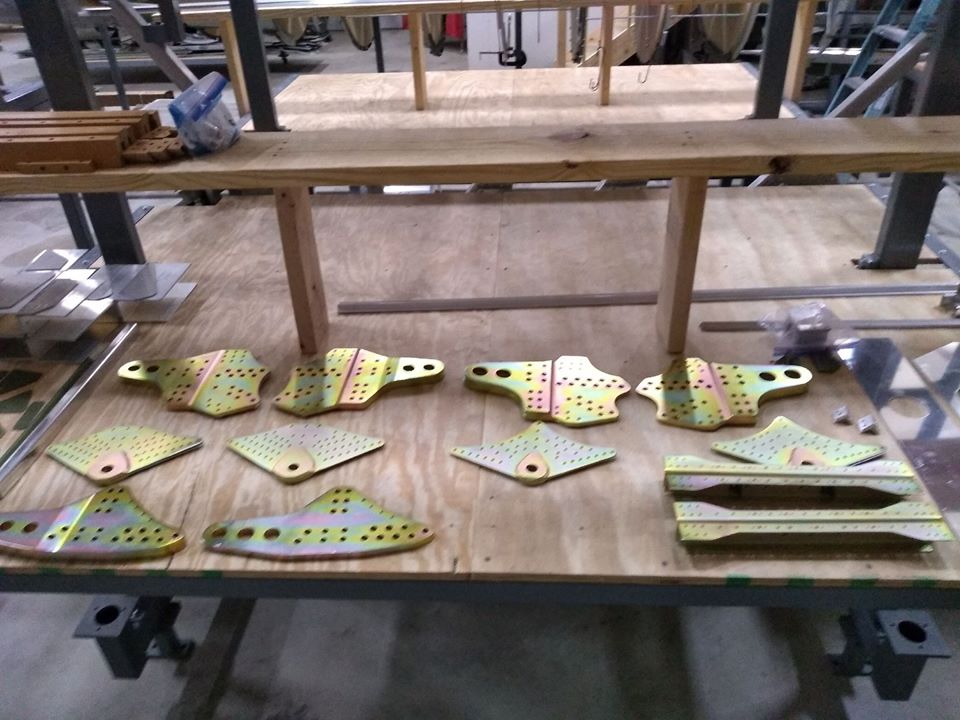
The newly cad-plated bomb bay bracket plates are laid out.
While it is not uncommon for the blueprints to call for parts to be cad-plated, they usually require silver cad. The bomb bay plates were originally gold-cad.
Photo taken 17 May 2020.
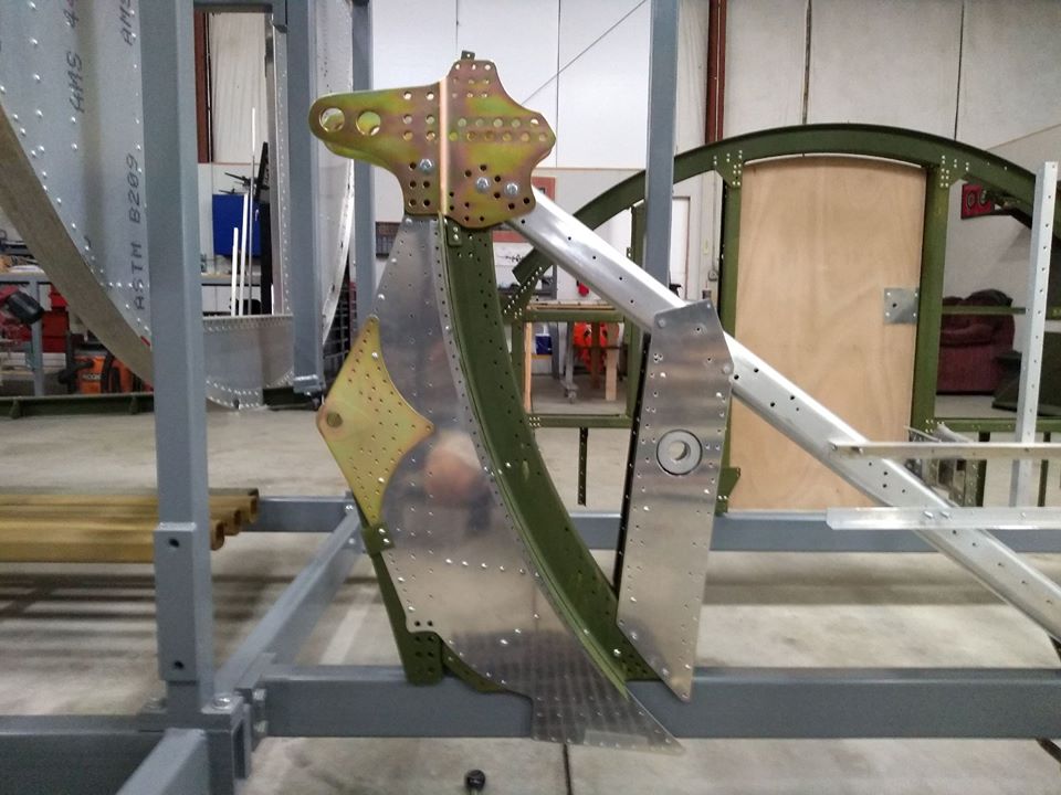
A pair of the newly cad-plated bomb bay bracket plates are test fitted to the carry-thru spar assembly that will go under Station 4.
Photo taken 17 May 2020.
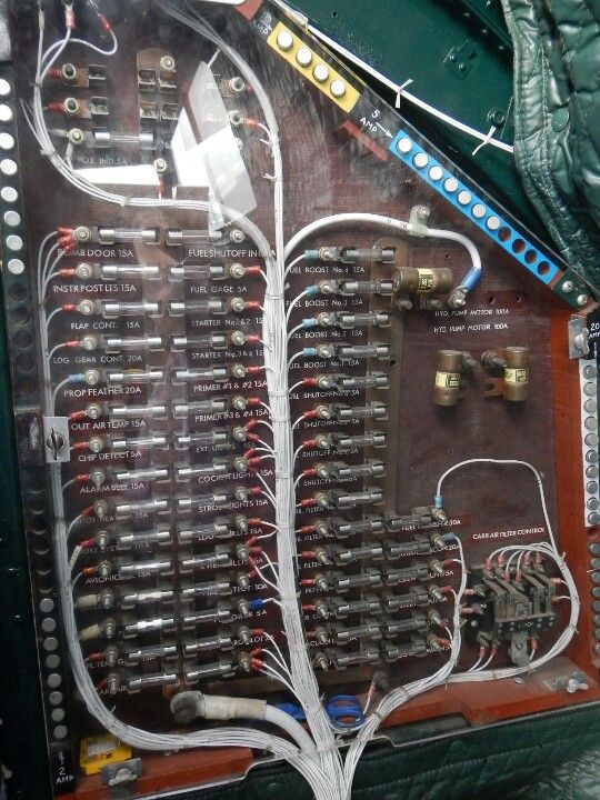
The cockpit fuse box aboard Yankee Lady (44-85829) of the Yankee Air Museum in Belleville, Michigan.
While somewhat different from an F-model box in design, the layout of the components themselves were very similar between the F and G boxes.
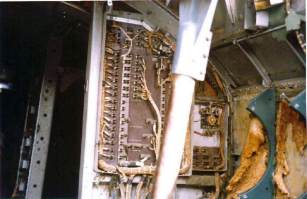
One of Karl’s photos from Memphis Belle back before any work had been done to her.
You can see here that the F fuse box was actually split into two boxes.
Note the ALCLAD markings on the wall to the right, now visible as the fabric and insulation has worn away.
So, as I mentioned in our last update, I took the Station 4 skins to my place to have their ALCLAD markings applied. That being finished, Megan and I went ahead and applied the markings for the manual landing gear cranks too.
Now, interestingly enough, the blueprints for these markings do not match the wreckage. The factory-applied markings were small decals with blue lettering. However, we have two airplane’s worth of wreckage that clearly show stenciled arrows instead. Going over Karl’s photos of Memphis Belle prior to her restoration, she too had white arrows. Must have been a Cheyenne modification…
So, we went with the arrows. The wreckage pieces were traced, scanned into the computer, cleaned, and printed into full-size stencils.
Speaking of Karl, he chided me saying that Belle’s bomb bay had been painted gray. This had been a concern of mine, as reference photos do show F-models with painted bomb bays. However, were able to confirm that Homesick Angel (42-3374) at Offutt AFB had an unpainted bomb bay all the way until her recent preservation. Since she is a Douglas F-model like Lucky Thirteen (slightly older, in fact), we are in good shape.
Besides – Don Price asked that we fly her unpainted for a little when she’s done. Haha!
In other news, our friends at the Douglas C-47 Night Fright recently sent us a gift of an AN6003-6 oxygen hose. You see, for a while we were using a Type A-6 Flare Container as a placeholder until we could locate the Type A-7 that was correct for the B-17. Since the A-6 was used on the C-47, we sent it to them once we were able to locate an A-7. These guys are doing an excellent job with their high-fidelity restoration. If you haven’t checked out their work already, you should take a look.
The B-17 carried eleven AN-6003-6 hoses and two AN6003-4 hoses as standard (the hyphenated numbers are the lengths in feet). Since we are working on the bomb bay, the newly donated AN-6003-6 will be going to the catwalk oxygen station. If you would like to help finish out the B-17F’s oxygen hose and tank complement, feel free to let us know!
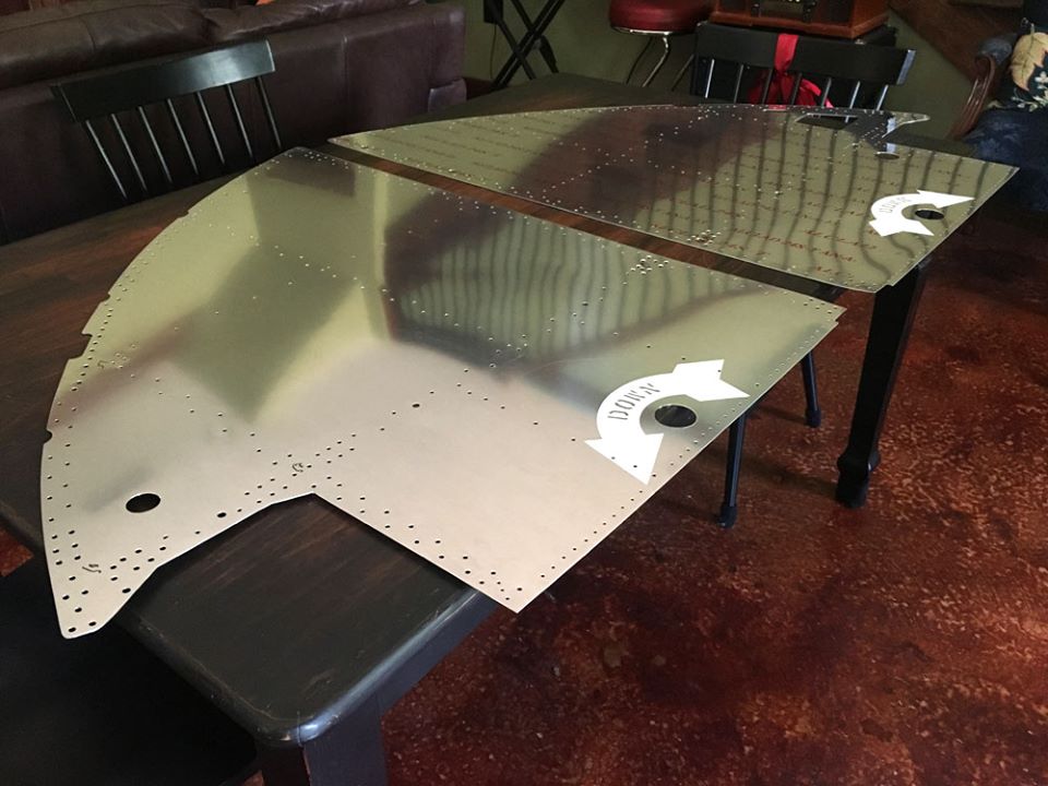
The skins to Station 4 from “Lucky Thirteen” are laid out on my dining table.
If you’re wondering where the ALCLAD markings are for the left panel – they are on the other side. It may be odd, but it matches the wreckage pieces we used for reference.
Photo taken 16 May 2020.

A close up of the stenciled arrow on the left panel.
There was some confusion as to which way the arrow should face on this panel. We had references showing both directions. So which was correct? Karl had the answer – apparently, it all depended on how the gear assembly was installed. Installed one way it turned left, but if installed the other way it turned right. Simple enough.
We opted for left.
Photo taken 16 May 2020.
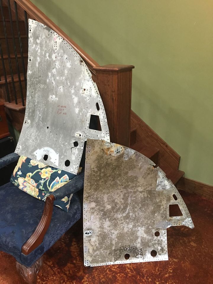
Right side Station 4s, taken from B-17 wrecks, sit at the bottom of my stairs for reference.
The ALCLAD markings on these panels are almost completely worn away. You have to get very close to see where they use to be.
Photo taken 13 May 2020.
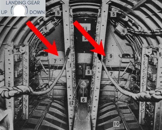
A photo from the manual is highlighted to show the factory-style manual gear markings.
We recreated these markings too, a low-res example of which you can see in the top left corner.
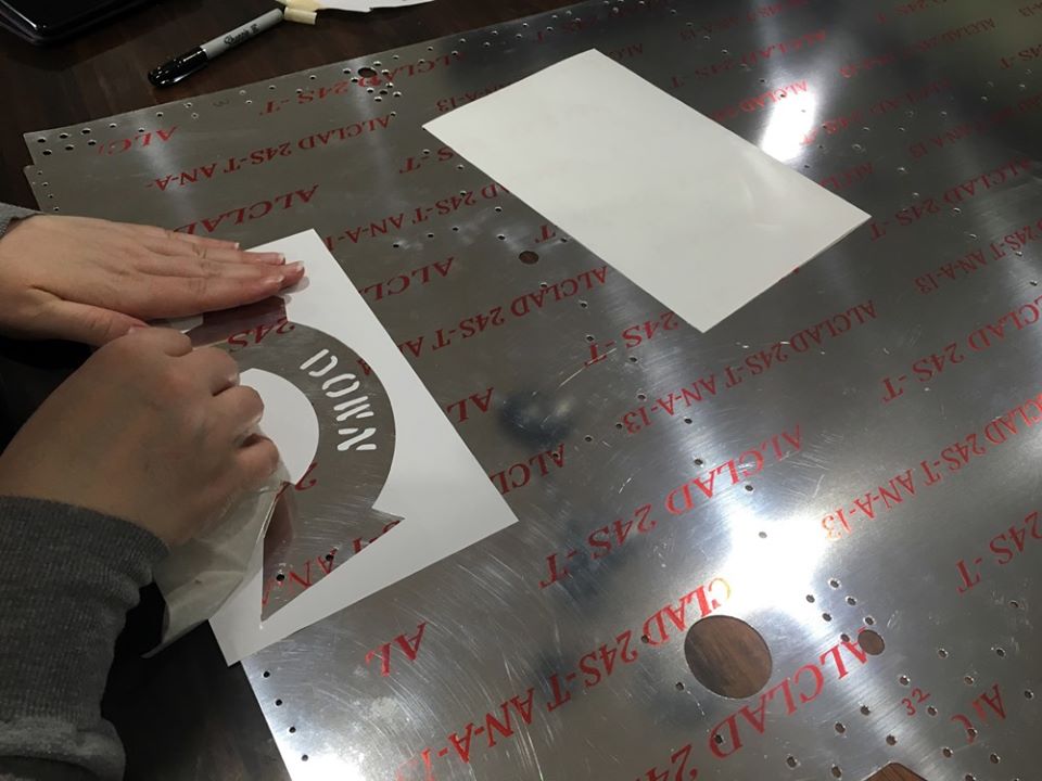
My wife Megan applies the stencil to the right side panel from Station 4.
Photo taken 13 May 2020.
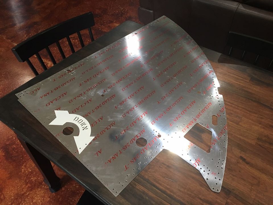
The finished manual gear marking on the right side panel of Station 4.
Photo taken 13 May 2020.
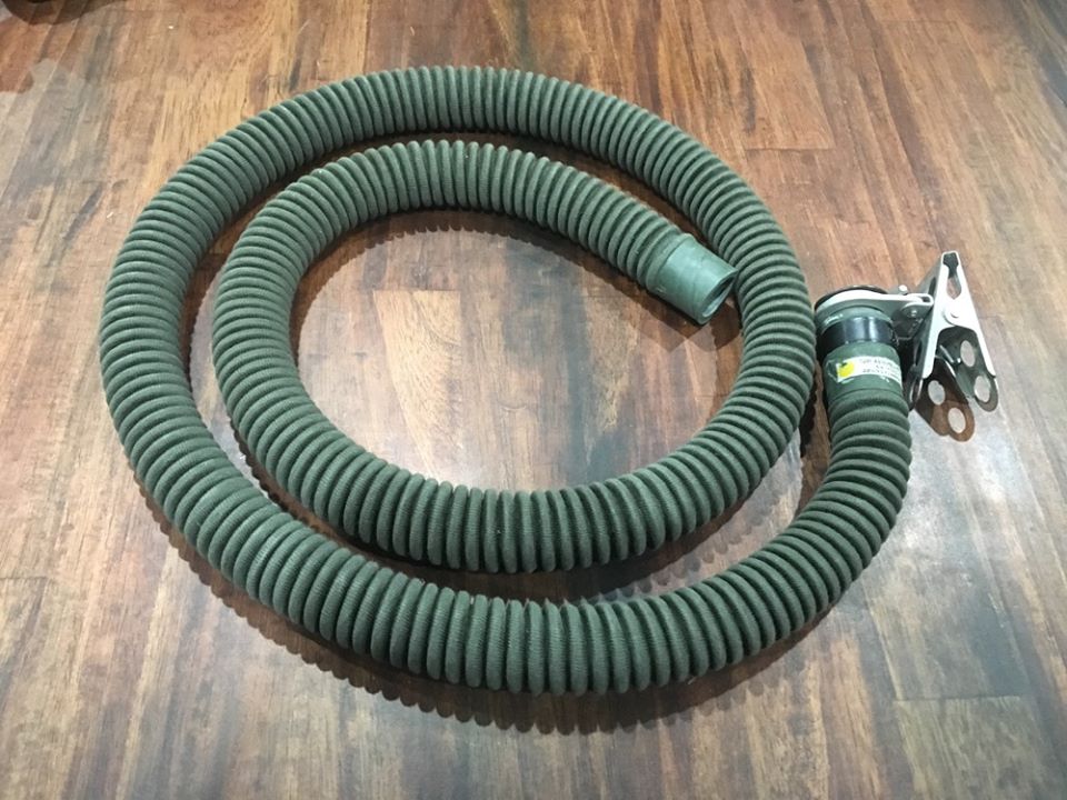
The AN-6003-6 oxygen hose sent to us from the team at Night Fright.
Photo taken 8 May 2020.
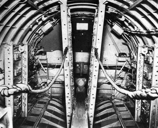
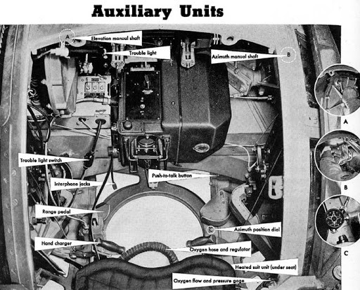
The bomb bay oxygen assembly on Station 5.
The portable oxygen bracket and urine relief tube have already been replicated.
Photo taken from the manual.
I couldn’t help myself…
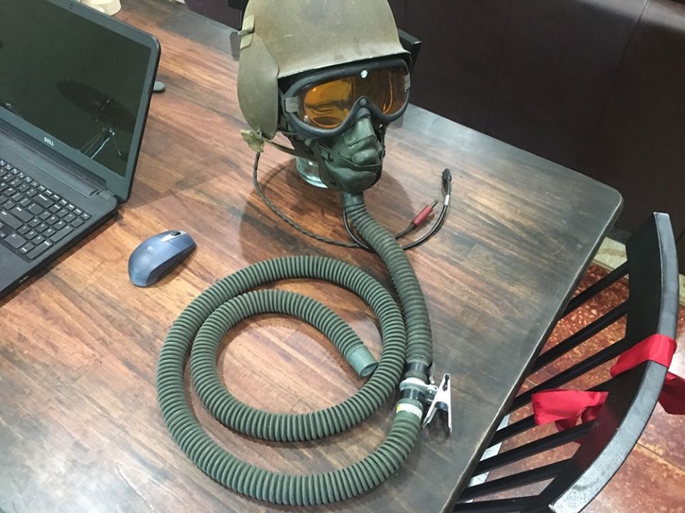
The AN-6003-6 oxygen tube is test fitted to a Type A-14 Oxygen Mask from my personal collection.
Photo taken 8 May 2020.
I recently visited our friend Fred Bieser – the turret restoration expert – down in Georgia. He had a ball turret seatplate he knew I would want to see.
Discoloring from age had left behind indicators of the seat cushion’s stitching. Fred knew I would want to trace it before he refinished the plate.
While I was there, Fred showed me some new stuff he was working on, so I thought I might share some of it.
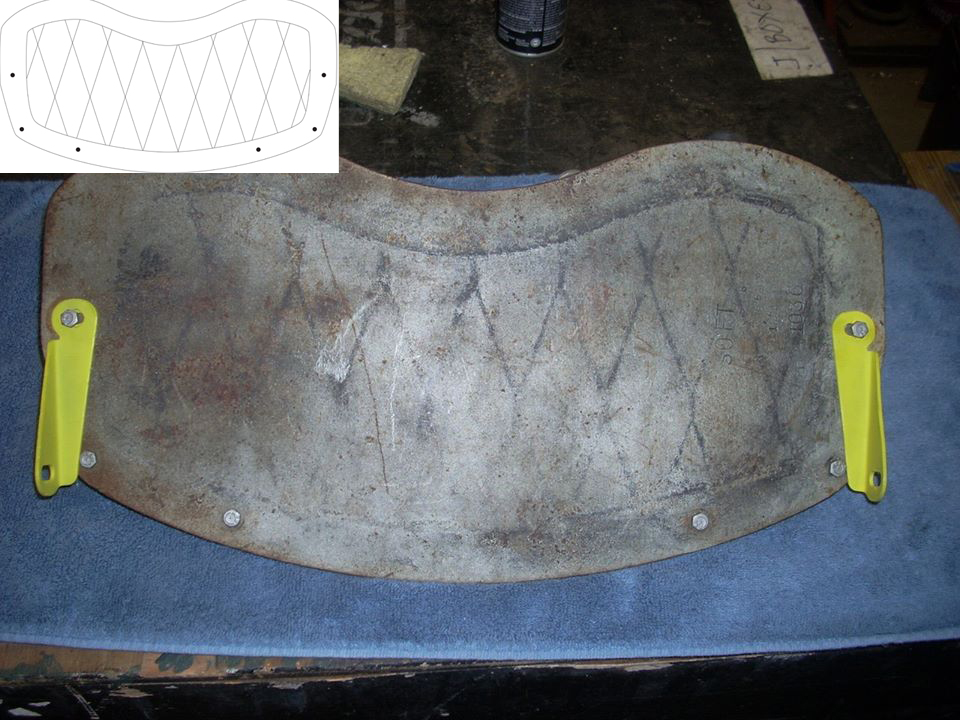
Tracing the ball turret seat and the markings from the old cushion.
The plate was traced onto Megan’s drawing pad and the stitching onto a sheet of clear plastic. Afterwards, the two were scanned into the computer and cleaned, resulting in the drawing in the top-left corner.
Photo taken 25 April 2020.
Manual illustration of a ball turret with a cushion stitched like Fred’s example.
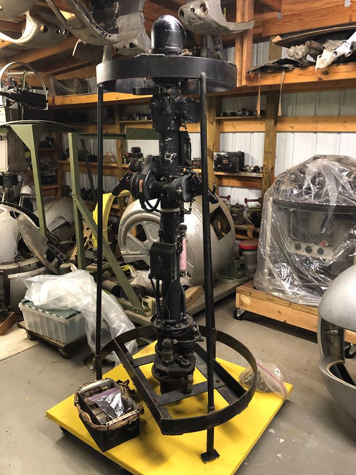
Fred recently acquired this rare periscope assembly from an early Douglas A-26.
Similar to the Boeing B-29, this fire-control system allowed the gunner to control both the upper and lower turrets via a single controller, which was sighted through a dual-ended periscope. In practice, this remote system was notoriously unreliable and the lower turret was often removed. Naturally, the lower scope on this assembly was deactivated and had to be returned to its original state.
Photo taken 25 April 2020.
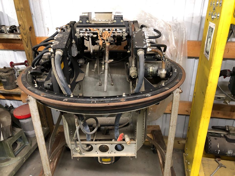
Like the turrets on the Boeing B-29, the gun turrets on the Douglas A-26 were designed by General Electric.
This GE turret from a A-26 is a recent acquisition and, according to Fred, is the most pristine example of a turret he has yet seen. I wouldn’t be surprised – the original placards and stickers all appear untouched.
Photo taken 25 April 2020.
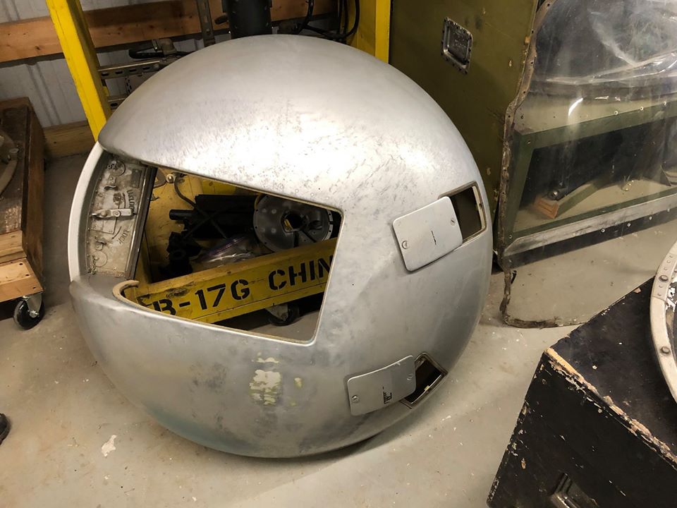
The outer shell to the Douglas A-26 GE turret that Fred recently acquired.
The felt which is meant to seal off outside air is still fully pliable.
Photo taken 25 April 2020.
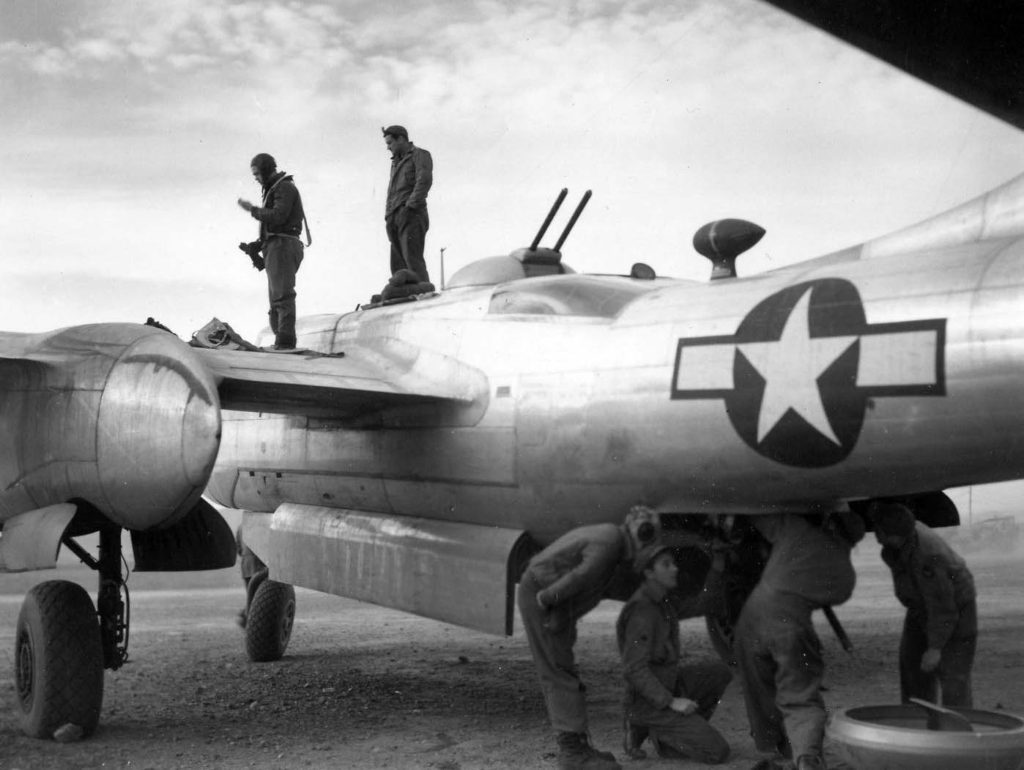
Armorers tend to the belly turret of a 47BG Douglas A-26C.

One of Fred’s several Martin 250CE turrets.
This particular example is notable as its ancillary pieces reveal it to have come from an RAF aircraft.
The Martin 250CE was easily the most successful turret of the war and a few Avro Lancaster variants were equipped with them. “Bomber” Harris had pushed for RAF BC to upgrade its defensive armament to .50 caliber MGs, but outside the Martin 250CE, little real progress was made on this issue.
Photo taken 25 April 2020.