
I must also admit that a lot of my recent work has been on small components that do not exactly warrant individual articles.
Still, many of our followers are not on Facebook, and I would hate to deprive them of an opportunity to see these little additions. So here is a post detailing some of the smaller odds and ends I finished in the past couple months.
Many of the pieces below are from our Auxiliary Parts Drive, which is still ongoing. We have also made significant progress on our Radio Parts Drive, but I am holding back on showing many of these pieces until I have better photos.
If you wish to help by donating and/or locating parts, do not hesitate to contact us.
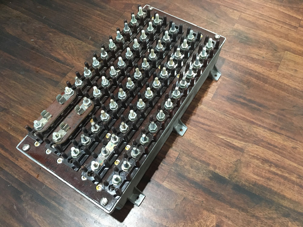
Photo taken 30 March 2019.
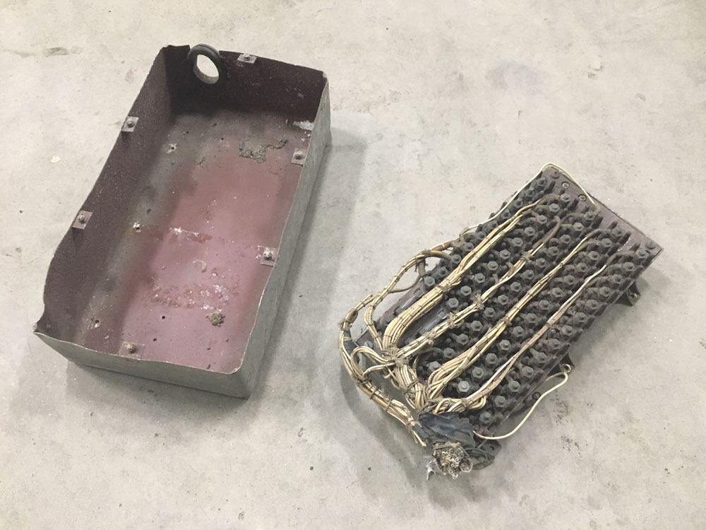
Photo taken 2 April 2019.
This is the BK-22 Relay for Lucky Thirteen‘s SCR-269 Radio Compass system.
Oddly enough, I had ordered the relay not knowing that we already had one. Thankfully, everything worked out. The BK-22 we had was in rough shape, while the ordered one was new-old-stock. The original piece should be helpful as a reference in setting up the untouched one.
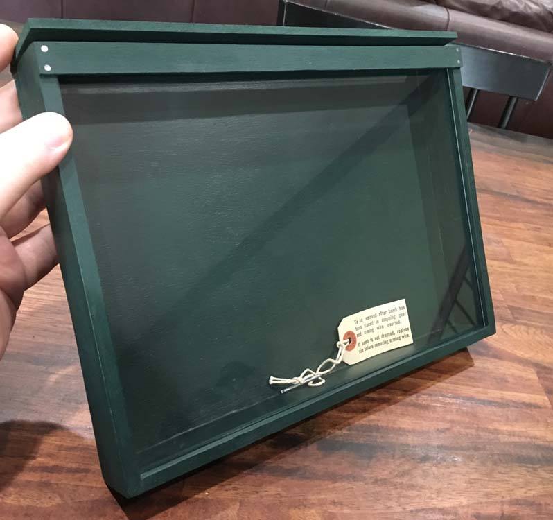
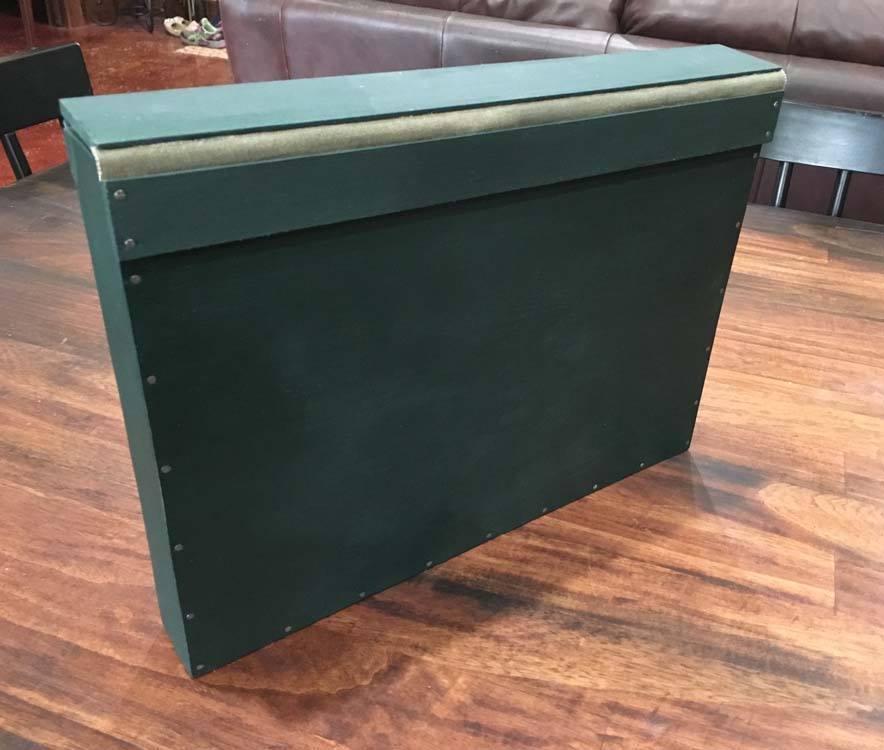
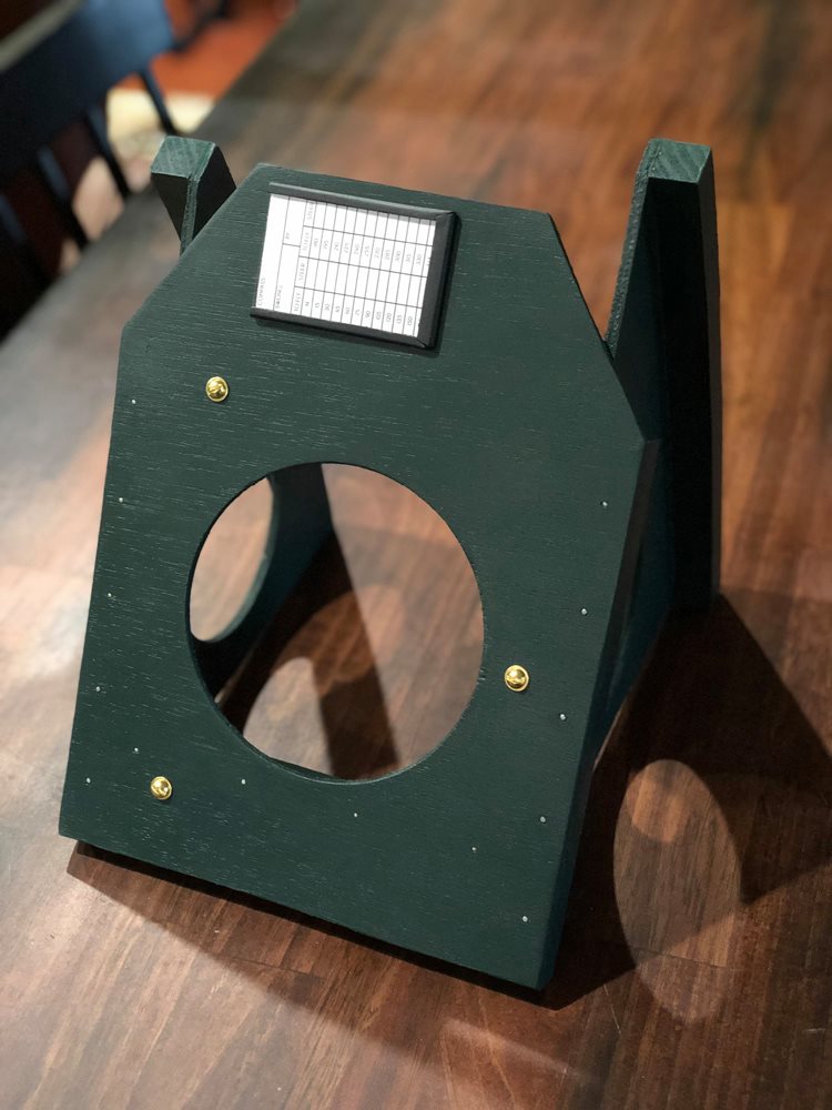
This is the Bombardier’s Data Card Box.
We really get a thrill whenever we do something that hasn’t been done since the war (as far as we know).
This shadow-box was used to display information on the bomber’s current bombload, changing out the charts inside as necessary.
On Es and early-Fs, this box was made of aluminum, though for late-Fs like Lucky Thirteen, the box was made of 3/16 inch plywood. Reference photos confirm that, while the metal versions were unpainted, wooden boxes were painted Bronze Green.
Interestingly, the blueprints called for the box top’s hinge to be made from OD canvas. Sacrificing an old duffel bag for the material, we had to cut the grooves out by hand for the canvas to attach. It took a lot of work to get right, but in the end, the top bounces open just like in the photos.
An original bomb fuse tag is in the box as a nod to the reference photo. The tag was a gift from my wife.
The only missing pieces now are a pair of metal tension clamps to hold the top shut. Ray will handle that later.
I am currently building two more of these boxes for the Planes of Fame Museum in Chino, California and the B-17 Cockpit Project in Braintree, England.
Photos taken 15 March 2019.
The bombardier’s data card box is highlighted next to 1LT Walter E. Witt aboard Winning Run (42-29944, 303BG).
Photo taken on 6 September 1943 – the day that Lucky Thirteen was shot down.
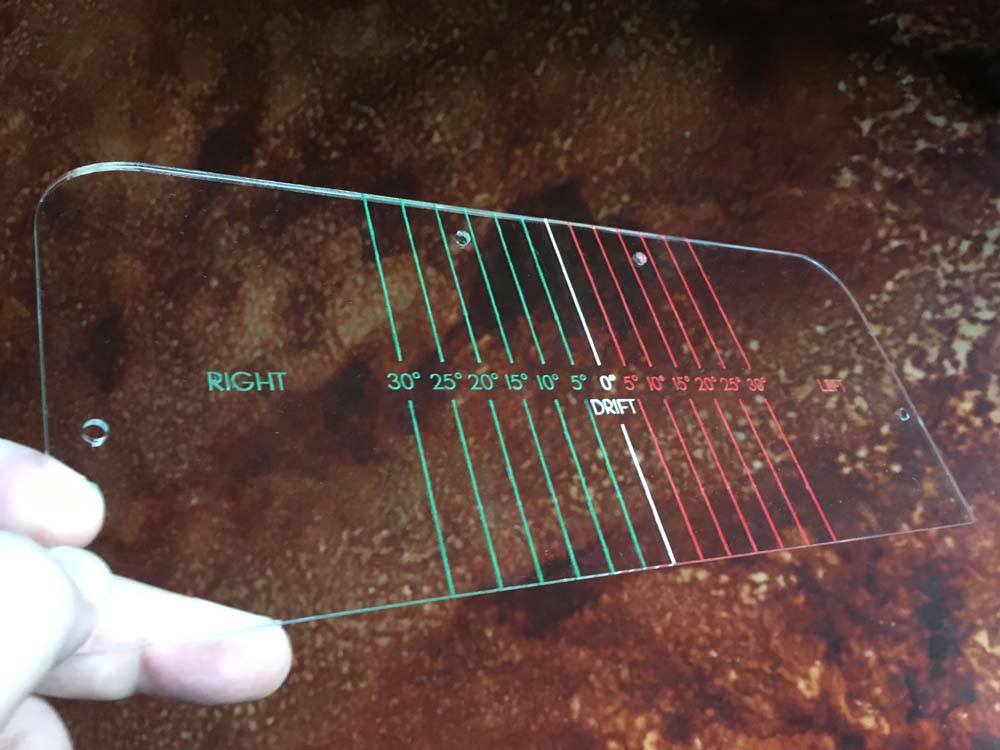
Photo taken 14 March 2019.
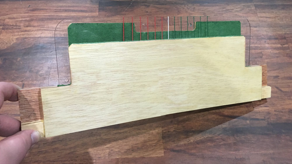
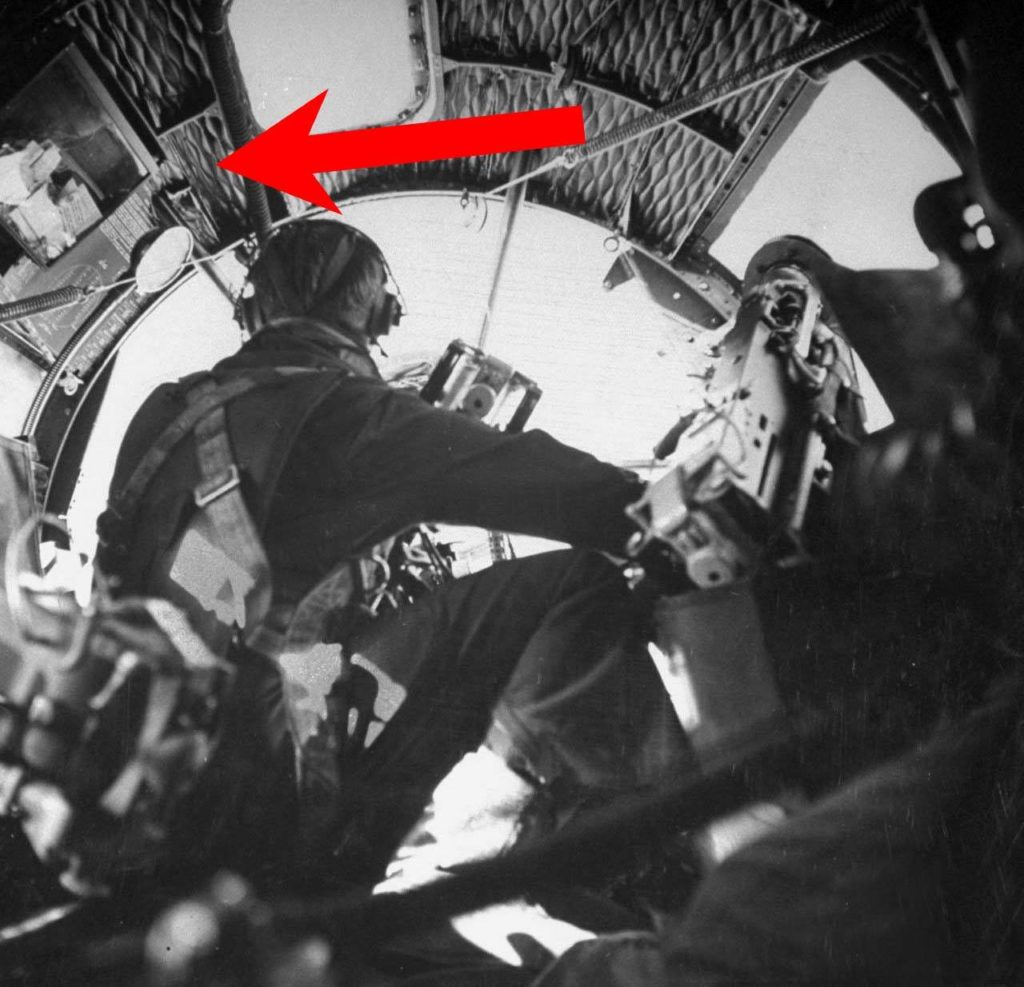
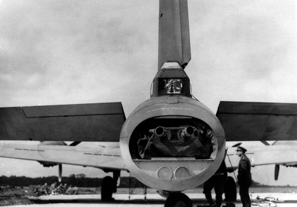
This is the Tail Gunner’s Azimuth Scale.
It took a couple tries to get it exactly right as the positioning is counter-intuitive – because he’s facing the opposite direction, everything for the tail gunner is backwards!
We used a high-quality plexiglass normally used to protect artwork so, in theory, it should never yellow with age.
My apologies for the poor photograph – this thing is hard to take pictures of. Even though the plexiglass is fairly thick, it is crystal clear. The cutting and etching on this piece was done by Trophies Unlimited of Aiken, South Carolina, nice people who have been extremely supportive of our work.
The wooden piece is the Azimuth Scale Holder, used to stow the piece when not in use.
Photo taken 2 April 2019.
SSGT Frederick M. Wilson of the 97BG.
The Azimuth Scale was clipped onto the tail gunner’s sighting window as needed. However, it should be noted that it was a navigation tool and would not be left in place, having nothing to do with aerial gunnery.

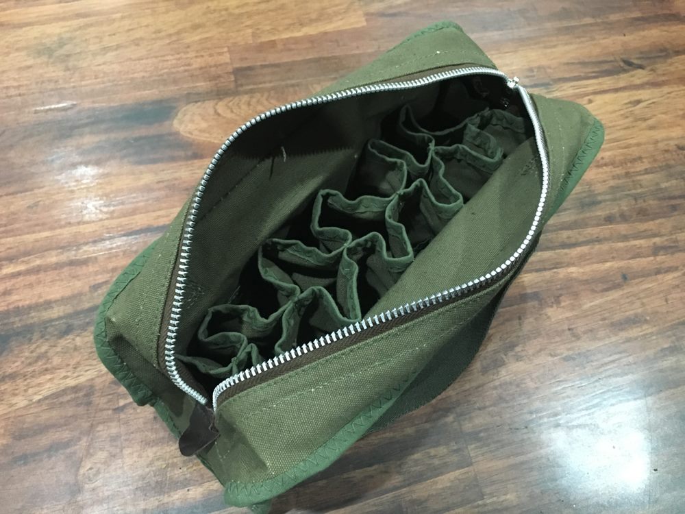
One of the more important pieces in the cockpit is the flare gun and its equipment. The B-17 carried a 37mm flare pistol, along with a pouch carrying several types of colored flares. Snap-attachments allowed the crew to quickly retrieve these pieces in an emergency, though a port in the roof also allowed the crew to use the flare gun in flight. (We are still looking for this mount.)
The blueprints call for a Type A-7 container for the flares, though they also make allowances for other variants. This A-6 type differs only in being an inch shorter in length (holding 12 flares rather than 18) and came to us from a lady who lives at the former proving grounds in Dugway, Utah.
Andy Rivera has already offered an M-8 Flare Pistol (made during the war by Eureka Vacuum) as well as a collection of unused flares.
Astute readers might note that the Flare Holder appears greener than the OD No. 3 fabric typically associated with Army Air Forces equipment. No worries – the Flare Holder is correct, the rich green tint is the camera’s fault.
Photos taken 9 March 2019.
*Since making this update, the correct A-7 container has been acquired.
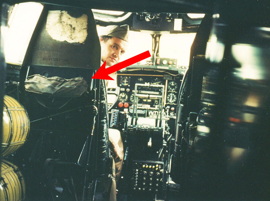
1LT Bob M. Welty of the 398BG peeks over the pilot seat in a rare color interior photo.
The aircraft’s flare container is highlighted here.
Five years ago, I wouldn’t have believed it if you had told me I’d end up working on a B-17. Life is rarely so kind.
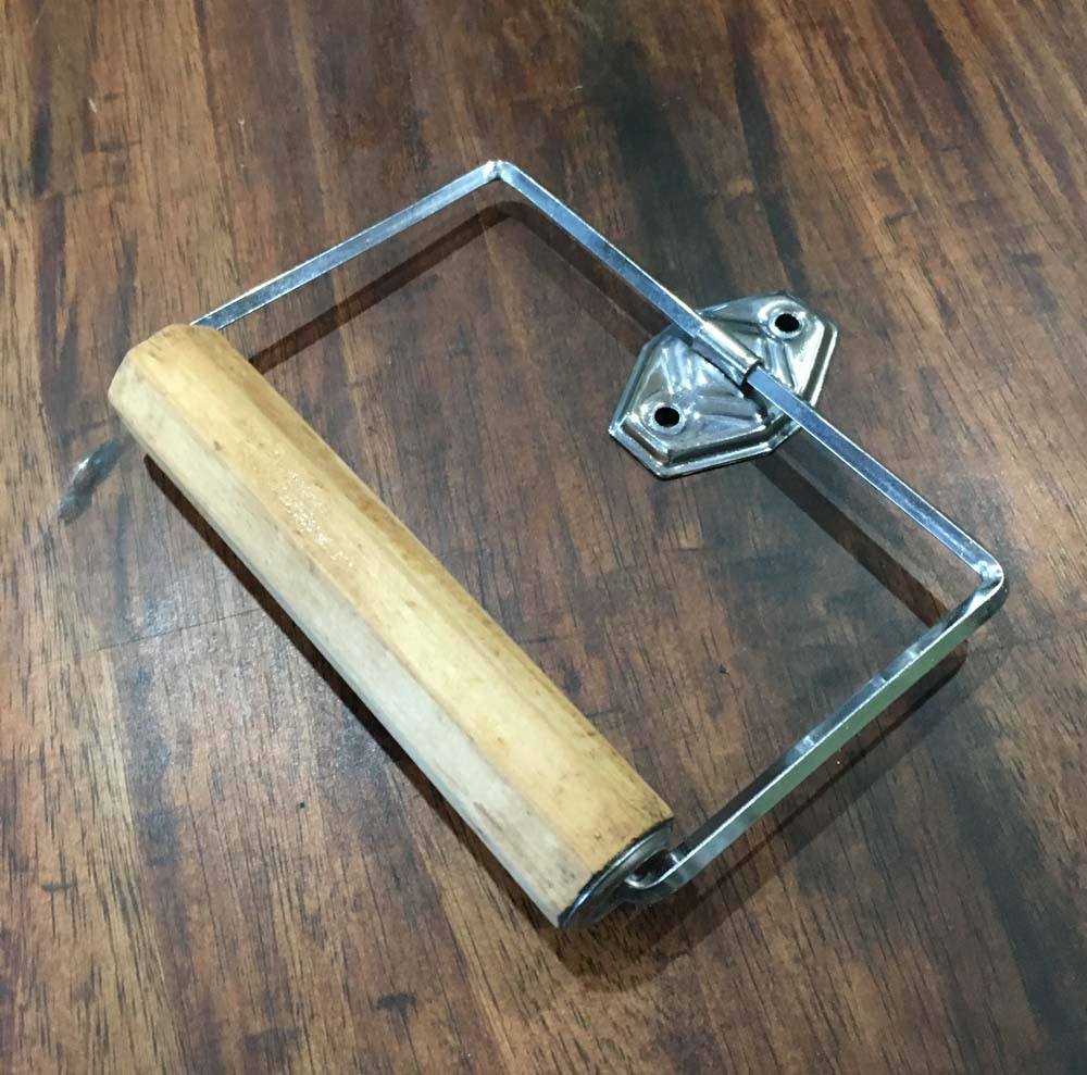
Still, I don’t think I would have ever expected to work so hard on a toilet paper holder.
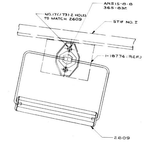
I had to track down and locate two separate holders from 1940s-era homes to get the parts I needed to recreate the original. Then, I had to clean and restore the pieces back to factory condition. Wartime holders were produced by Seattle Hardware as part no. 2609, though Autoyre also produced them on the civilian market.
The toilet paper holder was mounted on the wall beside Station 7, beside the waist entrance door and a Carbon Tet fire extinguisher.
While working on this project, I was able to track down another Toilet Paper Holder for the National Museum of the US Air Force where it will be installed in Memphis Belle.
Photo taken 6 March 2019.
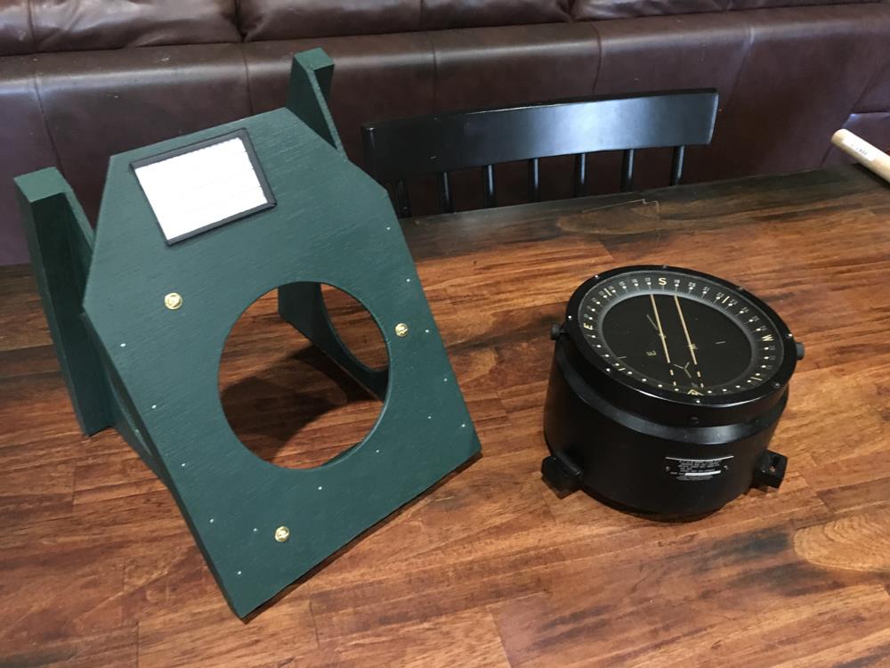
This is the bracket for the Navigator’s D-12 Compass, blueprint 15-7981.
The D-12 Compass was a regular fixture on early B-17s, mounted on a bracket on the wall behind the navigator. The bracket was metal up through block F-55 and wood from there-on to F-85, when the compass was removed altogether.
The blueprints require the screws and nails be brass to avoid upsetting the compass. Apparently, this did not help much in wartime service, as the D-12 was ultimately replaced by a remote compass mounted inside the wing.
On the topside of the shelf is a Compass Correction Card, along with its card holder.
Photos taken 25 February 2019.
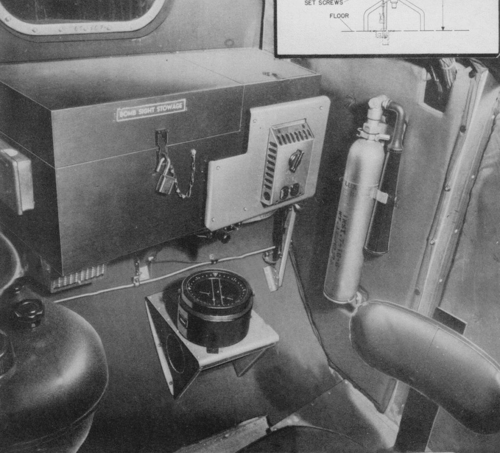
Manual photo of the earlier metal version, with the box above being the rarely-used Bombsight Stowage Box.
The stowage box was quickly replaced by stowing the bombsight in lockers on the airbase.
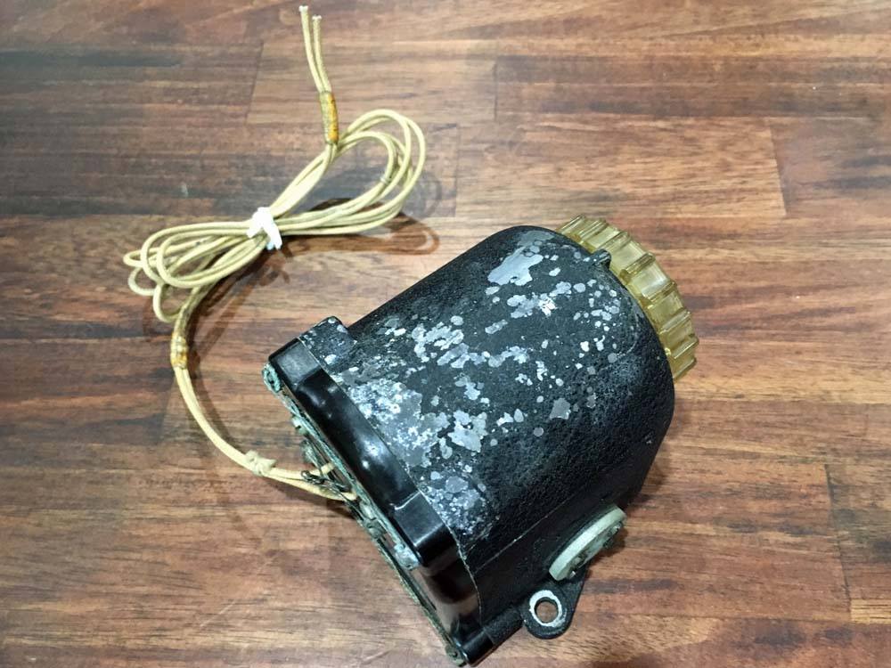
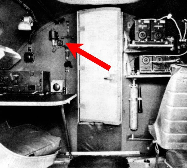
This is the BC-706 Inertia Switch for Lucky Thirteen’s IFF system.
Surviving IFF systems on Second World War warbirds are practically nonexistent. The Boeing B-17 went through three IFFs (Identify Friend From Foe Beacon) in its lifetime: the SCR-535, 595, and 695 – all variants of a British design. Lucky Thirteen served at a time when the most-likely installed IFF was the SCR-595.
The transponder was placed on a rack on the back of Station 6, near the ball turret, while the controls for the unit were placed on Station 5 above the radio operator’s desk. High priority was placed on making sure Allied IFFs never fell into enemy hands. As such, both the pilot and radio operator had destruct switches at their disposal.
Should the crew be unable to destroy the IFF, the BC-706 was designed to automatically destroy the IFF, using an inertia switch to detonate the charge upon impact.
While it needs repainting, the switch is otherwise in fantastic shape. The detonator spring still works!
This IFF comes to us from John Turanin of AeroAntique, who gave us a great deal in support of our efforts. John carries some amazing pieces and we highly recommend you check out his site.
Photo taken 22 February 2019.
*Since this update, the BC-706 shown here has been replaced with one featuring a cannon plug attachment, which appears more common of F-model B-17s.
Manual illustration of the IFF controls aboard a B-17F.
A sign of the high security surrounding the IFF, the control boxes for the IFF have been removed from this reference photo, leaving the mount (the T-shaped piece on the wall), power plug, and inertia switch behind.
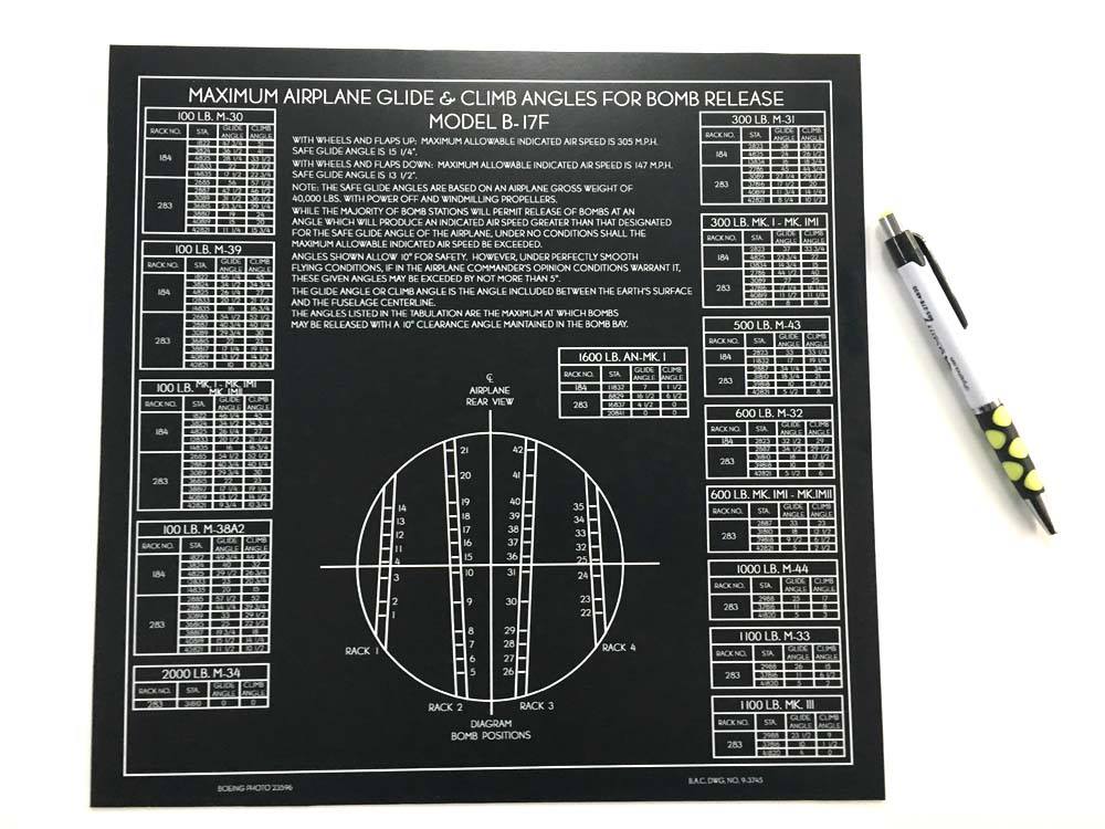
This is the Bomb Glide Angles Chart.
Up through B-17F-60, this chart was printed on a small, white card to the lower left of the bombardier. For the following variants, the chart was printed on black plastic and mounted to the bombardier’s upper right.
This is the latter chart.
At some point I intend to recreate the older chart for Memphis Belle, though I am a little wary as to how small the lettering will be.
Special thanks to Karl for finding the blueprint for this chart. I recreated everything by following an original blueprint, double-checking each number with references I had in the manuals. I am particularly happy with my drawing of the bomb-bay racks.
Photo taken 19 February 2019.
*Since this update, the chart for Memphis Belle has been created and installed. An original chart, with fluorescent markings, remains preferable to our recreation for Lucky Thirteen.
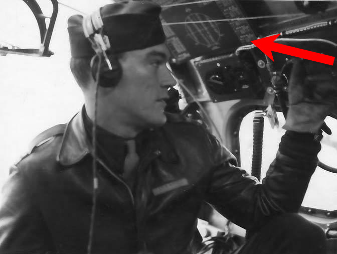
2LT Kent J. Keith of the 388BG, with the Glide Angles Chart highlighted.
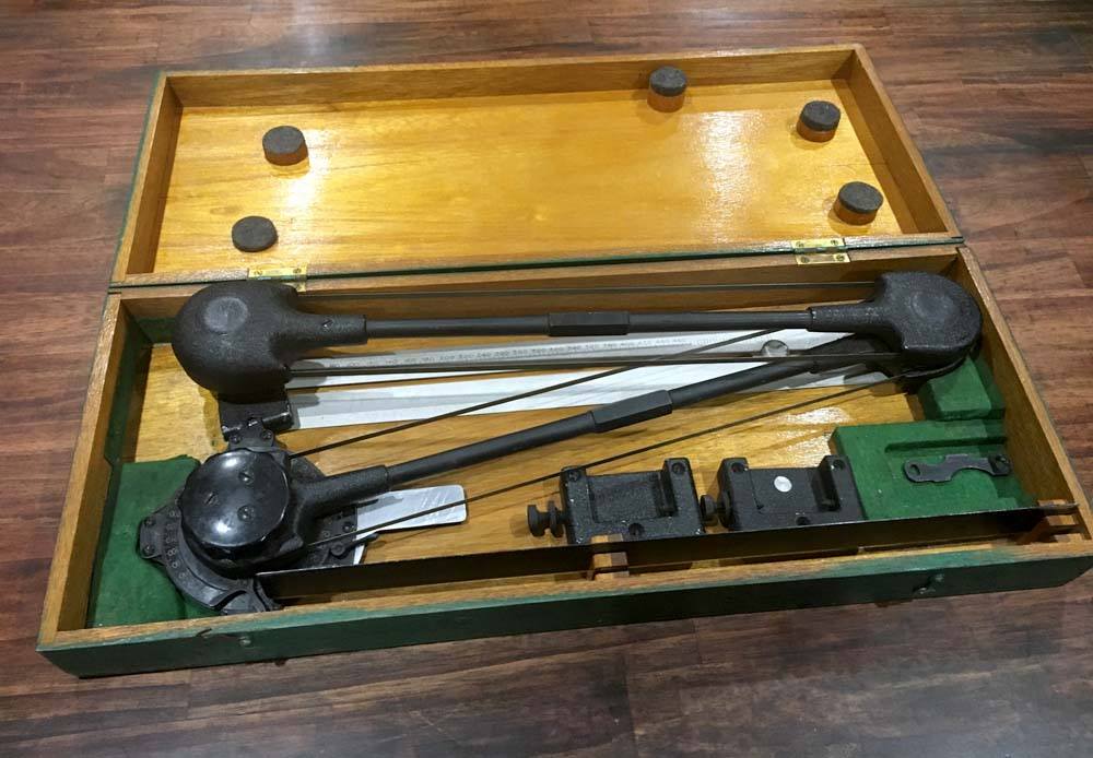
The AN5750 Course Plotter/Protractor, still in its original case. There is a slot for what appears to be another ruler, so this may be incomplete. This was found not far from Asheville and is one of those rare pieces you do not see much in modern restorations.
Photos taken 6 February 2019.
Photos taken 5 February 2019.
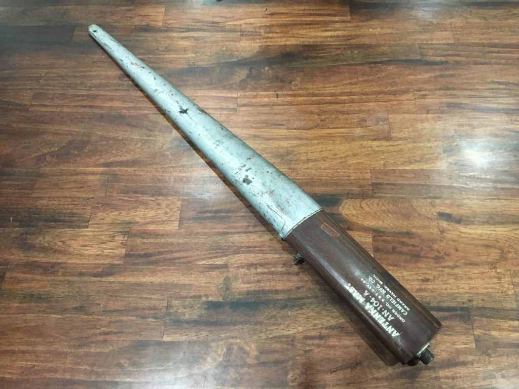
Photo taken 10 January 2019.
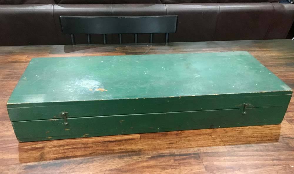
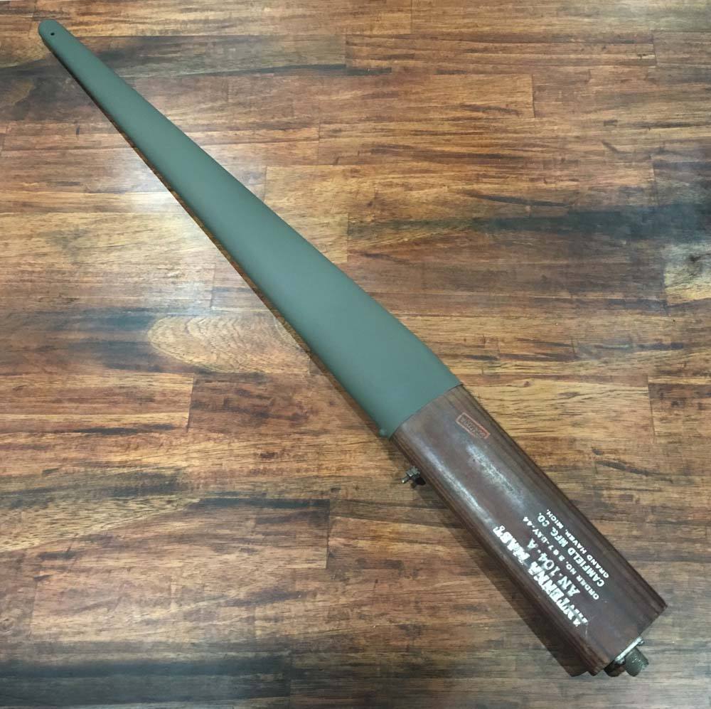
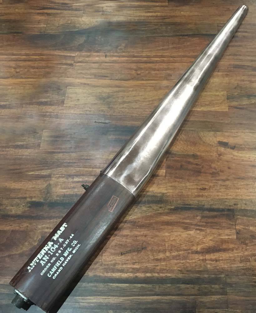
The final major component of Lucky Thirteen‘s SCR-522 VHF radio system: the AN-104-A.
Made by Camfield Manufacturing of New Haven, Michigan (a kitchen utensil company), the AN-104 came in three variants: Army, Navy, and postwar replacement. This is an original Army variant.
The only modification will be to add a tag to hold the line connecting the SCR-274 to the tail from the radio compartment – but that’s a long way in the future. I was able to get some advice from Charlie on how to properly clean and refinish the AN-104-A VHF antenna.
Oddly enough, we took greater care in painting the antenna than Camfield originally did. They had not properly masked the silver paint, resulting in some of it getting on the wood below. We carefully fixed this.
According to the blueprints, the antenna was held in place with two blocks of 2” maple. It took some time to find maple thick enough but we managed. My write-up on these blocks can be found here.
*Since posting this update, we have learned that Lucky Thirteen predated the AN-104-A, using an AN-74 antenna for her VHF system.
There was some concern when we began our Parts Drive that it might inadvertently raise the prices of the very parts we need. While that might eventually happen, the Parts Drive was exactly what motivated Andy Rivera of Delaware to complete the Navigator’s auxiliary equipment for us.
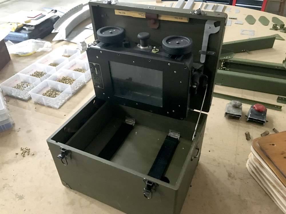
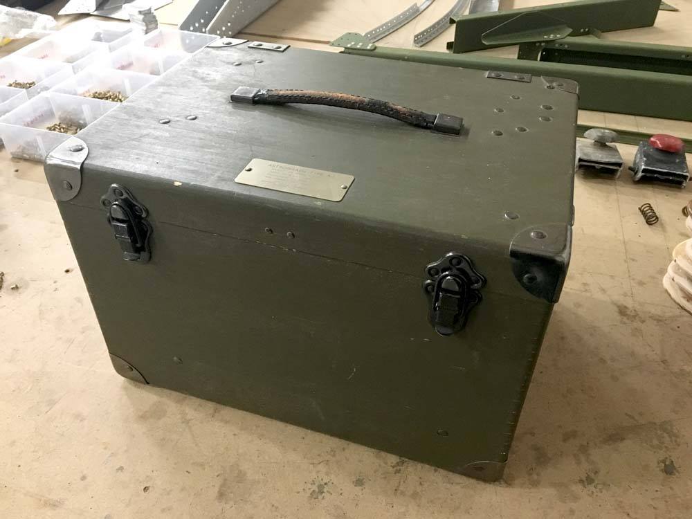
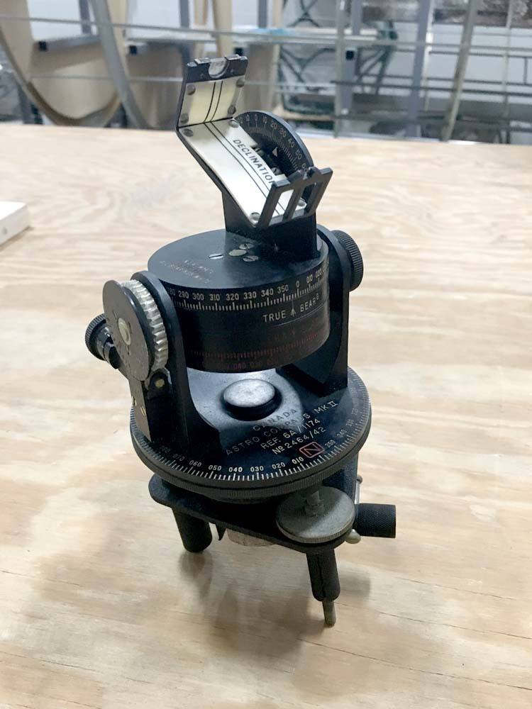
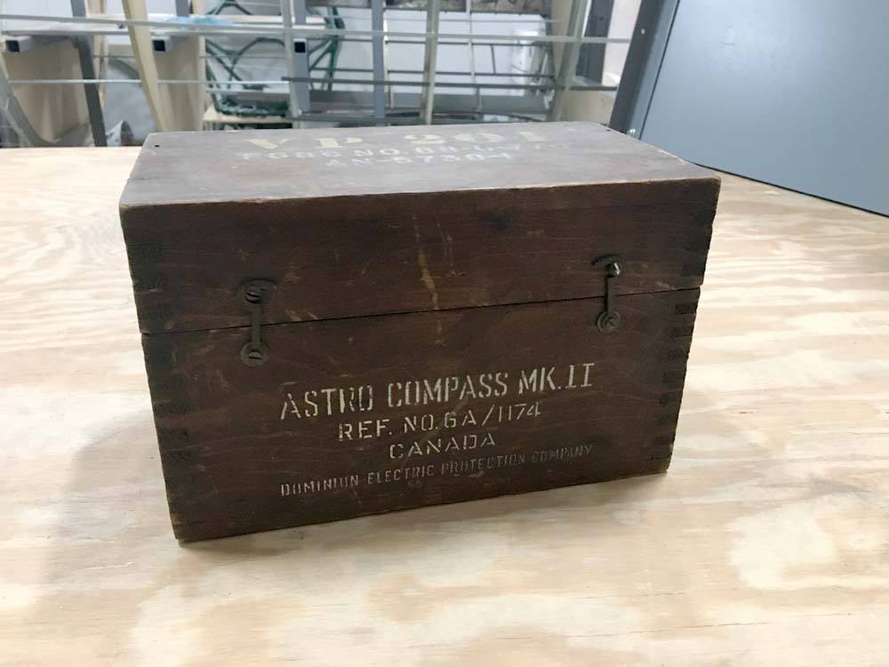
Andy purchased Lucky Thirteen’s astrograph and astrocompass (and since meeting us in person, has located the aircraft’s sextant).
The Kodak B-5 Astrograph and W. W. Boes Mk. II Astrocompass were both used for nighttime navigation and are not typically associated with the B-17.
While it is true that the US 8AF typically bombed by day, Lucky Thirteen flew at a time when there were serious discussions about abandoning daylight bombing over Europe. Starting on 8 September 1943 – just two days after Lucky Thirteen was lost – aircraft of the 305BG began participating in RAF night strikes. These aircraft were fitted with flame dampeners and flash suppressors, flying a total of eight night raids before stopping – only because of the arrival of Lockheed P-38 escorts.
In essence, the astrocompass (which is mounted in the astrodome) was used to take a reading from the stars, which was then plotted using the astrograph. Properly set-up, the astrograph projected the starfield onto a map which allowed the navigator to chart his position. This was a very clunky set-up and supposedly one of the more difficult aspects of navigation training.
Andy was a bit nervous about the astrocompass as he discovered upon its arrival that it had been made in Canada. We were not concerned because the American design was actually based on a British unit. As such, the only difference is the just the presence of the word “Canada.” No worries here. The US and RAF traded equipment regularly. This astrocompass may very well have been mounted in a US aircraft.
All we are missing are the mounts for these devices. If you happen to find them, do not hesitate to contact us.
Thanks again, Andy!
Photos taken 26 January 2019.
![]()
The fully restored BC-457 and BC-458 Command Transmitters sitting in their FT-226 Rack. The transmitter on the right was donated by the Asheville Radio Museum. Kudos to them!
The FT-226 Rack sits in a FT-227 Shock Mount. The shock mount was acquired still in its air-tight package, fresh from the war.
Steve Williams of Clarkson, Kentucky has offered to donate several parts for the Command Radio system, including the rare Command Relay and Mount, and is currently working on them now. This means the only major pieces of the Command Radio still needed are the FT-221 Shock Mount for the Receivers and the BC-451 Command Radio Control Box.
Photo taken 26 January 2019.
*Since this update we have been donated a complete SCR-274 system from Jack Antonio of Warner-Robins, Georgia.
![]()
The SCR-274 Command Radio system is highlighted in this manual photo from a B-17G.
Note the shelf below the radios, one of multiple locations where the IFF transponder was moved to in the G-series.
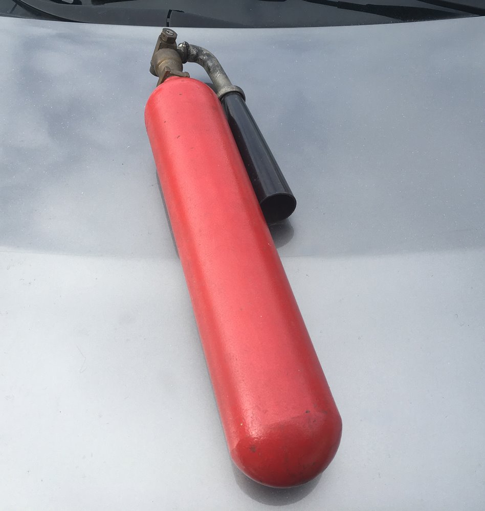
The B-17 carried three CO2 extinguisher sas standard, with one located in each of the enclosed compartments: the nose, the cockpit, and the radio room.
Boeing blueprints specify using the A-17 type, but also make allowances for the 4TB type should A-17s be unavailable. Both can be seen in period photos.
Today, the 4TB is much more readily available than the A-17. The tank is steel, the fittings are brass, the elbow is rubber, and the horn is plastic. This A-17 is the first step toward outfitting Lucky Thirteen with her CO2 extinguisher complement.
Photos taken 17 January 2019.

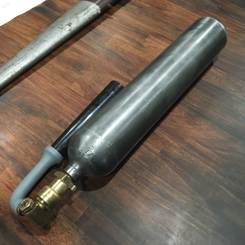
An A-17 is highlighted in the nose compartment of a B-17E.
Early units were unpainted and smooth. Later on, they were painted gray and wrapped with wire as a safety precaution.
Photo taken 2 April 1942.
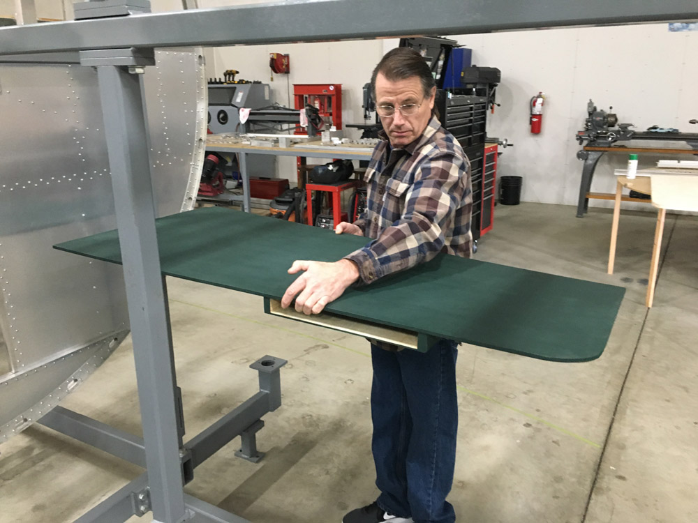
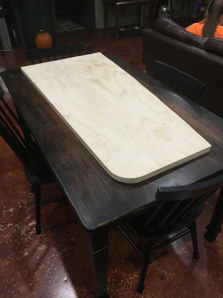
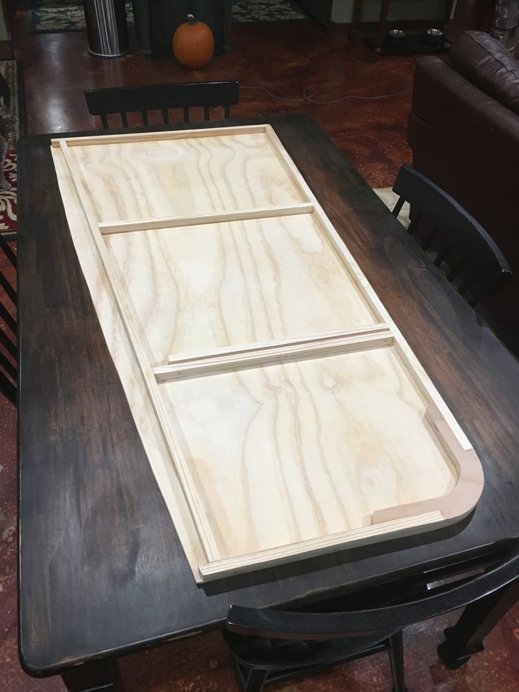
Ray holds the Cheyenne navigator’s table against Bulkhead 3 of Lucky Thirteen, were it will be later mounted.
This table was built based on limited references from the Cheyenne Modification Center. It may be necessary to redo this table should additional drawings become available.
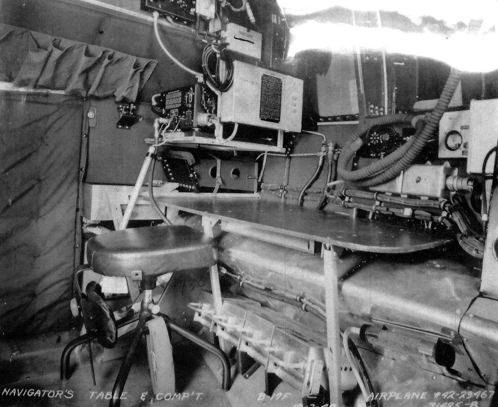
The Cheyenne navigator’s table aboard Flak Dodger (42-29467, 99BG), circa mid-1943.
Because of modifications that saw the installation of cheek guns, the stock Boeing table was usually removed from B-17Fs. This table, installed at the United Airlines Modification Center in Cheyenne, Wyoming, was far simpler design and sat considerably lower.
Note how the backrest on the Cramer Posture Chair has been installed upside down, so the navigator can waddle on and off his seat. Often, the bombardier and navigator’s seats were removed entirely.
Recalling my article on B-17 survivors, it is worth noting that all surviving B-17Gs are a late-production aircraft – meaning that they all were originally fitted with staggered waists and Cheyenne-style tail guns. The only exceptions being Shoo, Shoo Baby, awaiting display at the Smithsonian Udvar-Hazy Center, and Virgin’s Delight (43-38635) at Castle Air Museum in Atwater, California.
This means that the navigator’s table we built for Liberty Belle (above) is correct for virtually all surviving B-17Gs.
Liberty Belle’s table, shown here, was recreated using 3/8 thick 5-ply yellow poplar, braced as usual with strips of spruce. Finding this wood proved difficult, and I was not particularly happy with its durability – which is probably why the originals were so heavily lacquered.
Photos taken 25 November 2018.
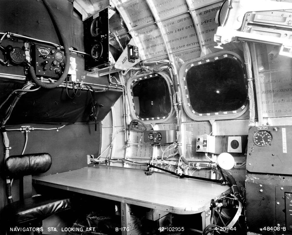
Factory photo of a typical late-G navigator’s table aboard Chatterbox II (42-102955, 351BG).
The Cramer posture chair on these navigator setups were mounted on a swivel, though offered little more leg room than the previous designs. The shelving, shown here holding the fluxgate and radio compass indicators, is a later variant and was usually supplemented with GEE system equipment.
Photo taken 20 April 1944.
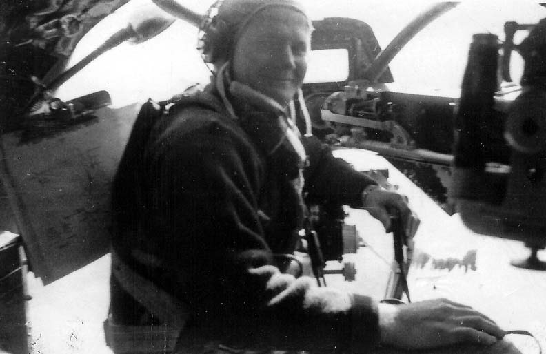
One piece that is unique to B-17Fs was a pair of Emergency Hand Brake levers mounted on the ceiling of the cockpit. We were able to purchase an original emergency brake as part of a batch-order.
Photo taken 27 December 2018.
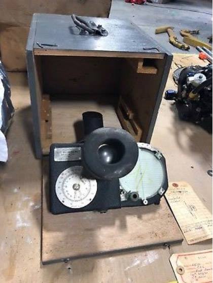
A pristine B-5 Drift Meter, fresh from long-term storage with the Royal Canadian Air Force, arrives in its original carrying case.
Photo taken 26 September 2018.
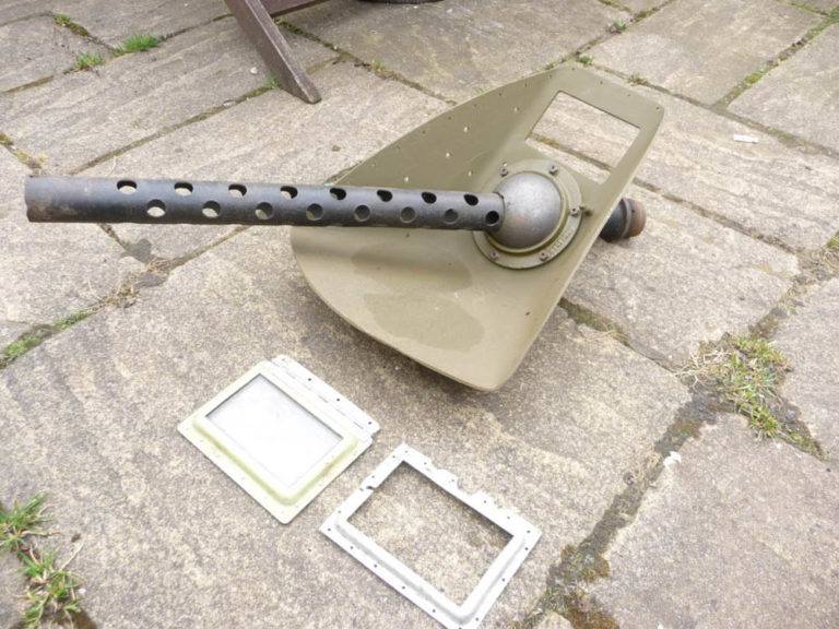
An incredibly rare M-1455 Nose Gun Mount traded to Hangar Thirteen by Colin Waterworth of Great Britain.
Photo taken 10 April 2018.

The clipboard is a Globe-Wernicke, which is a very good match for the Zellerbach Paper type called for in blueprint 1-21496. Thankfully, the blueprints allow for other brands of similar make and size.
Photo taken 30 March 2019.
2LT Bob G. Watkins of the 384BG.
Note the clipboard to the left.
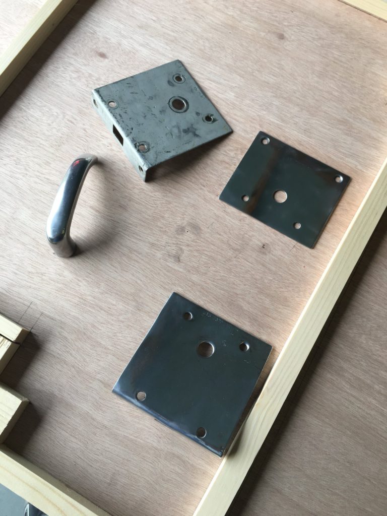
Going through our interior door hardware, these are the pieces that we identified as being original. The two plates on the right have been cleaned. The bend on both front plates will have to be redone.
The B-17 had a total of three hollow-core interior doors. This means that there were six handles, three forward plates, three back plates, and three latches.
Click here to read my write-up on building the interior doors.
Photo taken 5 April 2018.